HVAC LINE SET ANALYZING AND CHARGING SYSTEM
US20260185754A1
2026-07-02
19/547,295
2026-02-23
Smart Summary: A new system helps analyze and charge HVAC line sets, which are parts of heating and cooling systems. It has connectors for high and low-pressure sides of the HVAC system and a chamber for measuring gas. The system uses electronically controlled valves to manage the flow of gas and can switch between different modes like purging, measuring, testing for leaks, vacuuming, and charging. A precision pressure sensor measures the pressure inside the system to ensure everything works correctly. Overall, this system makes it easier and more efficient to maintain HVAC systems. 🚀 TL;DR
Abstract:
A system for analyzing and charging an HVAC line set is provided herein. The system includes an input connector configured to receive pressurized gas from an external source, an HVAC high port and an HVAC low port configured to connect to high-pressure and low-pressure sides of the HVAC line set, respectively, and a reference volume chamber fluidly connectable to the HVAC ports. The system further includes electronically controlled valves configured to selectively establish fluid pathways between the input connector, reference volume chamber, HVAC ports, and a vent, a vacuum connection configured to connect to a vacuum pump, a precision pressure sensor configured to measure pressure within the system, and a controller. The controller is configured to operate the valves in a purge mode, measurement mode, leak test mode, vacuum mode, and charge mode.
Inventors:
- Brandon Mallory 3 🇺🇸 Queen Creek, AZ, United States
- Douglass Macalister 3 🇺🇸 Glendale, AZ, United States
- Jesse Gee 1 🇺🇸 Phoenix, AZ, United States
Applicant:
Interested in similar patents?
Get notified when new applications in this technology area are published.
Classification:
F25B45/00 » CPC main
Arrangements for charging or discharging refrigerant
F25B2345/001 » CPC further
Details for charging or discharging refrigerants; Service stations therefor Charging refrigerant to a cycle
F25B2345/003 » CPC further
Details for charging or discharging refrigerants; Service stations therefor Control issues for charging or collecting refrigerant to or from a cycle
F25B2500/222 » CPC further
Problems to be solved; Preventing, detecting or repairing leaks of refrigeration fluids Detecting refrigerant leaks
F25B2700/19 » CPC further
Sensing or detecting of parameters; Sensors therefor Pressures
Description
CROSS-REFERENCE TO RELATED APPLICATIONS
This application is a continuation-in-part of U.S. application Ser. No. 19/029,756, filed Jan. 17, 2025, which is a continuation-in-part of U.S. application Ser. No. 18/638,839, filed on Apr. 18, 2024, now U.S. Pat. No. 12,352,483, which are hereby incorporated by reference in its entirety.
BACKGROUND
Technical Field
The present disclosure relates to HVAC servicing equipment, and more particularly to an automated system for analyzing and charging HVAC line sets that integrates an inert gas purging, volume measurement, leak testing, vacuum evacuation, and refrigerant charging functions through a unified valve-controlled fluid pathway architecture.
State of the Art
Heating, ventilation, and air conditioning (HVAC) systems are widely deployed in residential, commercial, and industrial buildings. These systems circulate refrigerant between indoor and outdoor units through copper tubing commonly referred to as a line set. The proper installation and servicing of HVAC systems involves multiple distinct procedures, including purging the line set with inert gas during brazing operations, testing for leaks, evacuating the system to remove moisture and non-condensable gases, and charging the system with the appropriate amount of refrigerant.
During the installation of HVAC systems, technicians braze copper connections to join the line set to the evaporator coil and condenser. When copper is heated during brazing without an inert atmosphere, oxidation occurs and carbon deposits can form inside the tubing. These deposits may subsequently clog filter driers and restrict refrigerant flow, which can degrade system performance and potentially damage components over time.
After brazing is complete, technicians perform leak testing to verify the integrity of the brazed joints and mechanical connections. This typically involves pressurizing the system with inert gas and monitoring for pressure decay over a specified period. If leaks are present, refrigerant charged into the system may escape into the atmosphere, which raises environmental concerns particularly with newer low global warming potential refrigerants that may be flammable.
Following successful leak testing, the line set is evacuated using a vacuum pump to remove atmospheric air and moisture. Regulatory guidelines establish thresholds for acceptable vacuum levels and require that the vacuum be maintained for a specified duration. Moisture remaining in the system can react with refrigerant and lubricating oils, forming acids that corrode internal components.
The amount of refrigerant required to charge an HVAC system depends in part on the volume of the line set, which varies based on the length of tubing connecting the indoor and outdoor units. In many installations, particularly retrofit applications, the line set runs through walls, ceilings, or underground, making direct measurement of its length impractical. Technicians have traditionally estimated line set length or relied on trial-and-error methods to determine the appropriate refrigerant charge, which can result in systems that are overcharged or undercharged.
Conventional approaches to HVAC installation and servicing involve the use of multiple separate tools and manual procedures for each phase of the process. Technicians typically connect and disconnect various pieces of equipment, such as nitrogen regulators, pressure gauges, vacuum pumps, micron gauges, and refrigerant scales, at different stages of the installation. Each connection and disconnection presents an opportunity for errors and atmospheric air to enter the system or for procedural steps to be abbreviated or omitted.
The industry has recognized the benefits of automating portions of the HVAC installation and servicing process. Some existing systems provide automated pressure testing and vacuum testing capabilities, while others focus on measuring line set length to determine refrigerant charge requirements. However, integrating multiple functions into a single apparatus while maintaining the ability to connect to the line set presents ongoing challenges.
Accordingly, there is a need for a HVAC line set analyzing and charging system that streamlines purging, volume measurement, leak testing, vacuum evacuation, and refrigerant charging functions.
SUMMARY OF THE INVENTION
In one embodiment, a system for analyzing and charging an HVAC line set is provided. In this embodiment, the system includes an input connector configured to receive a pressurized gas from an external source. The system may further include at least one port, such as, but not limited to, a first port and/or a second port, wherein the at least one port is configured to connect to a high-pressure side or a low-pressure side of the HVAC line set, or the first port and the second port may be configured to connect to a high-pressure side and a low-pressure side of the HVAC line set. The system also includes a reference volume chamber fluidly connectable to the line set. The system includes a plurality of electronically controlled valves configured to selectively establish fluid pathways between the input connector, the reference volume chamber, the line set, and a vent. The system further includes a vacuum connection configured to connect to a vacuum pump. The system also includes at least one precision pressure sensor configured to measure pressure within the system. The system includes a controller configured to operate the plurality of electronically controlled valves in a purge mode to flow an inert gas through the HVAC line set. The controller is further configured to operate the plurality of electronically controlled valves in a measurement mode to pressurize the HVAC line set to a first pressure, isolate the HVAC line set, open a valve connecting the HVAC line set to the reference volume chamber, and calculate a volume of the HVAC line set based on a pressure drop between the HVAC line set and the reference volume chamber. The controller is further configured to operate the plurality of electronically controlled valves in a leak test mode to pressurize the HVAC line set to a second pressure higher than the first pressure and monitor for pressure decay. The controller is further configured to operate the plurality of electronically controlled valves in a vacuum mode to evacuate the HVAC line set through the vacuum connection. The controller is further configured to operate the plurality of electronically controlled valves in a charge mode to introduce refrigerant into the HVAC line set through the input connector.
In another embodiment, a system for determining line set volume and charging an HVAC system is provided. In this embodiment, the system includes an input connector configured to receive a pressurized gas from an external source. The system may further include at least one port, such as, but not limited to, a first port and/or a second port, wherein the at least one port is configured to connect to a high-pressure side or a low-pressure side of the HVAC line set, or the first port and the second port may be configured to connect to a high-pressure side and a low-pressure side of the HVAC line set. The system also includes a reference volume chamber fluidly coupled to the line set. The system includes a vacuum connection configured to connect to a vacuum pump. The system further includes a controller configured to operate a purge mode to flow an inert gas through the HVAC line set via both the ports during brazing operations. The controller is further configured to operate a measurement mode to pressurize the HVAC line set to a first pressure, isolate the HVAC line set, introduce the reference volume chamber, and calculate a volume of the HVAC line set based on a pressure drop between the HVAC line set and the reference volume chamber. The controller is further configured to operate a leak test mode to pressurize the HVAC line set to a second pressure higher than the first pressure and monitor for pressure decay. The controller is further configured to operate a vacuum mode to evacuate the HVAC line set through the vacuum connection. The controller is further configured to, in response to determining a refrigerant charge amount based on the calculated volume of the HVAC line set, operate a charge mode to introduce refrigerant into the HVAC line set through the input connector to the refrigerant charge amount.
In yet another embodiment, a method for analyzing and charging an HVAC line set using a unified apparatus having at least one port, a reference volume chamber, and a plurality of electronically controlled valves is provided. In this embodiment, the method includes connecting the at least one port to one of a high-pressure side or a low-pressure side of the HVAC line set, respectively. The method further includes performing a purge operation by operating the plurality of electronically controlled valves to flow an inert gas through the HVAC line set via both the at least one port during brazing operations. The method also includes performing a volume measurement operation by evacuating the reference volume chamber to a vacuum state, pressurizing the HVAC line set to a first predetermined pressure through the HVAC high port and the HVAC low port, isolating the pressurized HVAC line set, opening a valve to fluidly connect the pressurized HVAC line set to the evacuated reference volume chamber, measuring a pressure drop, and calculating a volume of the HVAC line set based on the first predetermined pressure, the pressure drop, and a known volume of the reference volume chamber. The method further includes performing a leak test operation by pressurizing the HVAC line set to a second predetermined pressure higher than the first predetermined pressure and monitoring for pressure decay over a specified time period. The method also includes performing a vacuum operation by evacuating the HVAC line set through a vacuum connection and monitoring vacuum levels. The method further includes performing a charge operation by introducing refrigerant into the HVAC line set based on the calculated volume of the HVAC line set.
The foregoing and other features and advantages of the present invention will be apparent from the following more detailed description of the particular embodiments of the invention, as illustrated in the accompanying drawings.
BRIEF DESCRIPTION OF THE DRAWINGS
A more complete understanding of the present invention may be derived by referring to the detailed description and claims when considered in connection with the Figures, wherein like reference numbers refer to similar items throughout the Figures, and:
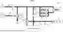
FIG. 1 is a system diagram of an HVAC line set analyzing and charging system configured in a purge mode, in accordance with an embodiment;
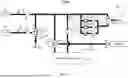
FIG. 2A is a system diagram of the HVAC line set analyzing and charging system of FIG. 1 configured in a first measurement mode, in accordance with an embodiment;
FIG. 2B is a system diagram of the HVAC line set analyzing and charging system of FIG. 1 configured in a second measurement mode, in accordance with an embodiment;
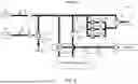
FIG. 3 is a system diagram of the HVAC line set analyzing and charging system of FIG. 1 configured in a leak check mode, in accordance with an embodiment;
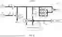
FIG. 4 is a system diagram of the HVAC line set analyzing and charging system of FIG. 1 configured in a vacuum mode, in accordance with an embodiment; and
FIG. 5 is a system diagram of the HVAC line set analyzing and charging system of FIG. 1 configured in a charge mode, in accordance with an embodiment.
DETAILED DESCRIPTION OF EMBODIMENTS OF THE INVENTION
As discussed above, embodiments of the present invention relate to an automated system for analyzing and charging HVAC line sets that integrates inert gas purging, volume measurement, leak testing, vacuum evacuation, and refrigerant charging functions through a unified valve-controlled fluid pathway architecture. While various embodiments herein describe the system as being coupled to a HVAC line set, it should be understood that embodiments of the invention are not limited to this configuration. It is understood that in the industry, the terms ‘line set,’ ‘refrigerant line,’ and ‘refrigerant circuit’ may be used interchangeably herein. The systems and methods described may be utilized to analyze, purge, and calculate the volume of any HVAC refrigerant line (line set), including tubing located entirely internally within a self-contained HVAC unit, a packaged unit, or integrated directly onboard a condenser or evaporator unit during manufacturing or field operation.
Referring to FIG. 1, a system 10 for analyzing and charging an HVAC line set is shown configured in a purge mode. The system 10 may be used to perform multiple functions during HVAC installation and service operations, including purging with an inert gas, such as, without limitation, inert gas, measuring line set volume, performing pressure testing, evacuating the line set, and charging with refrigerant.
The system 10 includes an input connector 12 configured to receive a pressurized gas from an external source. The input connector 12 may be connected to an external inert gas source by an installer before operation begins. A gate valve on the external inert gas source may be opened by the installer to supply inert gas to the system 10. The external inert gas source provides the pressurized gas used during purge, measurement, and leak test operations.
A first valve 14 is positioned downstream of the input connector 12 and is configured to selectively direct the pressurized gas through different pathways within the system 10. The first valve 14 may route the pressurized gas to various components depending on the operating mode of the system 10.
A precision pressure sensor 16 is configured to measure pressure within the system 10. The precision pressure sensor 16 monitors pressure levels during various operating modes and provides feedback to a controller for automated operation.
A main solenoid 18 controls flow through a measurement pathway within the system 10. The main solenoid 18 may be operated by the controller to selectively permit or block gas flow through the measurement pathway.
One or more regulators 20 are configured to regulate pressure of the pressurized gas at different pressure levels for different operating modes. The regulators 20 may regulate the pressurized gas to a first regulated pressure, which is a first predetermined pressure, such as, but not limited to, between 2 and 3 psi during the purge mode, to a second regulated pressure, which is a second predetermined pressure, such as, but not limited to, approximately 50 psi during a measurement mode, and to a third regulated pressure, which is a third predetermined pressure, such as, but not limited to, approximately 250 psi during a leak test mode. An internal regulator within the regulators 20 automatically sets pressure the first regulated pressure during the purge mode for brazing operations.
With continued reference to FIG. 1, the system 10 includes a plurality of electronically controlled valves configured to selectively establish fluid pathways between the input connector 12, a reference volume chamber, a first port, a second port, and a vent. The plurality of electronically controlled valves includes a first shutoff valve 21 and a first pressure valve 22 utilized for the first regulated pressure, a second shutoff valve 23 and a second pressure valve 24 utilized for the second regulated pressure, and a third shutoff valve 25 and a third pressure valve 26 utilized for the third regulated pressure. All electronic valves within the system 10 start in the closed position when the system 10 is powered on.
The system 10 may further include optional manual valves that begin in the open position and are controlled by the installer or technician. The combination of electronically controlled valves and any optional manual valves provides comprehensive flow control throughout the system 10.
A vacuum 30 provides a vacuum connection configured to connect to a vacuum pump. A vacuum shutoff valve 32 controls fluid communication between the vacuum 30 and the remainder of the system 10. As shown in FIG. 1, the vacuum shutoff valve 32 is in a closed position when the vacuum 30 is not operating.
One or more vacuum sensors, such as, but not limited to, a control vacuum sensor 34 and a micron vacuum sensor 36 may be positioned along a vacuum pathway to monitor vacuum levels during evacuation operations. The one or more vacuum sensors provide feedback to the controller regarding vacuum conditions within the system 10.
A reference volume 40 provides a reference volume chamber fluidly connectable to the line set. A second valve 42 is positioned between the reference volume 40 and a fluid pathway connecting the HVAC high port and the HVAC low port. A valve vent 44 associated with the second valve 42 is shown in a closed position during the purge mode. The reference volume 40 is used for volume measurement calculations during the measurement mode.
A first port 50 is configured to connect to a high-pressure side of the HVAC line set. A first port valve 52 controls flow to the first port 50, and a first sensor port 54 monitors pressure at the connection to the high-pressure side. The system 10 uses hosing connections from the device to valves at the condenser.
A second port 60 is configured to connect to a low-pressure side of the HVAC line set. A second port valve 62 controls flow to the HVAC low port 60, and a second sensor port 64 monitors pressure at the connection to the low-pressure side. The first port 50 and the second port 60 together enable the system 10 to interface with both sides of the HVAC line set simultaneously.
A vent 70 provides an exhaust pathway for gases during various operations. A third valve 72 controls flow to the vent 70. A valve vent 74 is shown in a closed position during the purge mode. A purge temperature sensor 76 is positioned proximate to the vent 70 and is configured to monitor temperature during the purge mode. The purge temperature sensor 76 captures temperature data during brazing operations.
As shown in FIG. 1, red arrows indicate the flow direction of inert gas through the system 10 during the purge mode. The controller operates the plurality of electronically controlled valves in the purge mode to flow an inert gas through the HVAC line set via both the first port 50 and the second port 60 during brazing operations. During the purge mode, the first shutoff valve 21 is in an open position, while the first pressure valve 22, second shutoff valve 23, second pressure valve 24, third shutoff valve 25, and third pressure valve 26 are in closed positions. with the first shutoff valve 21 and the first pressure valve 22 open the purge mode operates at the first regulated pressure.
The system 10 may or may not be coupled to the evaporator coil to create a loop for testing purposes, to the condenser coils to create a loop for testing purposes, or both for testing purposes. These configurations enables inert gas to flow through the entire line set and may or may not include the evaporator coil, the condenser coil, or both during purge operations, measurement operations, leak test operations, and/or charging operations.
The system 10 records the duration of the entire brazing process along with temperature and pressure spikes and dips during purge operations. When an installer presses a stop brazing purge function, the system 10 captures and formats all recorded information. The system 10 then reverts all electronic valves back to closed positions and enters standby mode after completing the purge phase.
Referring to FIG. 2A, the system 10 is shown configured in a first measurement mode. In the first measurement mode, the system 10 performs a volume measurement operation by evacuating the reference volume chamber 40 to a vacuum state. The second shutoff valve 23 and the second pressure valve 24 may be positioned in open positions to create a fluid pathway between the vacuum 30 and the reference volume 40. The vacuum shutoff valve 32 may also be positioned in an open position during the first measurement mode to enable evacuation of the reference volume 40.
With continued reference to FIG. 2A, the system 10 may perform a vacuum evacuation of the reference volume 40 and an inert gas path before measurement operations commence. During the vacuum evacuation, the control vacuum sensor 34 and the micron vacuum sensor 36 may continuously monitor pressure levels within the system 10. The continuous monitoring of pressure sensors allows the controller to track evacuation progress and detect any anomalies during the evacuation process.
Following the vacuum evacuation, the system 10 may close certain valves and wait another predetermined period of time to detect changes in pressure sensors for leak detection purposes. If the pressure sensors indicate pressure changes during the wait period, the system 10 may determine that a leak is present. If no leaks are detected based on stable pressure readings, the measurement sequence may continue.
As further shown in FIG. 2A, the system 10 may illuminate a visual signal to prompt an installer to open the inert gas source during the measurement sequence. The visual signal provides a clear indication to the installer that the system 10 is ready for the refrigerant tank to be opened. When the installer opens the inert gas source, such as a nitrogen tank, container or other type of source, in response to the visual signal, the system 10 may detect a positive pressure reading to confirm that the technician has opened the inert gas source. Upon detecting the positive pressure reading confirming the inert gas source has been opened, the system 10 may remove the visual signal and proceed with subsequent steps of the measurement sequence.
Referring to FIG. 2B, the system 10 is shown configured in a second measurement mode for a pressure drop. In the second measurement mode, the HVAC line set has been pressurized to a second pressure, such as the second regulated pressure, through the first port 50 and the second port 60.
With continued reference to FIG. 2B, once the HVAC line set reaches the second regulated pressure, the controller operates the plurality of electronically controlled valves to isolate the pressurized HVAC line set. In the isolated state, the first shutoff valve 21, the first pressure valve 22, the second shutoff valve 23, the second pressure valve 24, the third shutoff valve 25, and the third pressure valve 26 are all shown in closed positions. The vacuum shutoff valve 32 is also shown in a closed position. This valve configuration isolates the pressurized HVAC line set from the input connector 12, the vacuum 30, and the vent 70.
As further shown in FIG. 2B, the second valve 42 is positioned between the reference volume 40 and a fluid pathway connecting the first port 50 and the second port 60. The second valve 42 may selectively connect the reference volume 40 to either the vacuum connection or the fluid pathway connecting the first port 50 and the second port 60. In the second measurement mode, the second valve 42 is in a closed position and the main solenoid 18 is in the open position that fluidly connects the pressurized HVAC line set to the evacuated reference volume 40. Orange arrows in FIG. 2B indicate the flow direction between the HVAC connections and the reference volume 40 during this measurement phase, showing a drop between the pressurized line set and the reference volume 40.
The controller operates the plurality of electronically controlled valves in the measurement mode to pressurize the HVAC line set to the first pressure, isolate the HVAC line set, open a valve connecting the HVAC line set to the reference volume chamber, and calculate a volume of the HVAC line set based on a pressure drop between the HVAC line set and the reference volume chamber. The precision pressure sensor 16 measures a pressure drop after the pressurized HVAC line set and the reference volume 40 reach equilibrium.
The controller calculates the volume of the HVAC line set based on the first predetermined pressure, the pressure drop, and a known volume of the reference volume chamber. Using the ideal gas law and the measured pressure values, the controller may determine the unknown volume of the HVAC line set. The controller may further calculate a line set length based on the calculated volume of the HVAC line set. The controller may calculate the line set length based on the calculated volume of the HVAC line set and a known cross-sectional area of tubing comprising the HVAC line set. By dividing the calculated volume by the known cross-sectional area of the copper tubing, the controller determines the length of the line set.
The controller may further subtract a known volume or the like, such as, without limitation, a stored internal coil volume from a total system volume measurement to determine the line set length. Manufacturer data for internal coil volumes of evaporator coils and condenser coils may be stored in a database accessible by the controller. The subtraction method allows the controller to isolate the line set volume from the total measured system volume, providing a more accurate determination of the line set length and the corresponding refrigerant charge amount.
Upon completion of the volume measurement, the system may provide information in various ways, such as, without limitation, generating a QR code confirming inert gas purge during brazing and volume measurement completion, or sending the data electronically, wirelessly or by other means. The data may including the duration of the brazing purge, temperature readings captured during brazing, pressure measurements, the calculated line set volume, and the calculated line set length. The data provides a digital record that may be scanned and stored for documentation and verification purposes.
Referring to FIG. 3, the system 10 is shown configured in a leak check mode. In the leak check mode, the controller operates the plurality of electronically controlled valves to pressurize the HVAC line set to a second pressure higher than the first pressure used during the measurement mode and monitor for pressure decay. The leak check mode may be used to verify the integrity of brazed connections and mechanical fittings before proceeding with evacuation and refrigerant charging operations.
In the leak check mode configuration shown in FIG. 3, the first shutoff valve 21 is in a closed position, the first pressure valve 22 is in a closed position, the second shutoff valve 23 is in a closed position, and the second pressure valve 24 is in a closed position. The third shutoff valve 25 and the third pressure valve 26 are in open positions. This valve configuration establishes a flow pathway for inert gas from the input connector 12 through the system 10 to the first port 50 and the second port 60.
With continued reference to FIG. 3, inert gas enters the system 10 through the input connector 12 and flows through the first valve 14. The inert gas passes through the main solenoid 18 and the regulators 20, which may regulate the inert gas to a higher pressure suitable for leak testing. The inert gas flows through the open third shutoff valve 25 and the open third pressure valve 26 toward the high pressure valve 52 and the low pressure valve 62. The red arrows in FIG. 3 indicate the flow direction of inert gas through the system 10 during the leak check mode.
The system 10 pressurizes the HVAC line set to the third regulates pressure during the leak test mode for high-pressure testing. This third regulated pressure of 250 psi is higher than the first regulated pressure and higher than the second regulated pressure. The higher pressure provides a more rigorous test of the HVAC line set integrity and may reveal leaks that would not be detectable at lower pressures.
Once the HVAC line set reaches the third regulated pressure, the controller closes the first shutoff valve 21 to isolate the inert gas source from the pressurized HVAC line set. The system 10 then monitors the leak test for a predetermined amount of time, such as, without limitation, 30 minutes, to detect pressure decay indicating leaks. The precision pressure sensor 16 and the high pressure sensor port 54 and low pressure sensor port 64 may monitor pressure levels throughout the specified time period.
During the predetermined amount of time establishing the monitoring period, the controller performs a leak test operation by monitoring for pressure decay over the specified time period. If pressure drops at a fast rate during the monitoring period, the controller determines that a leak is detected in the HVAC line set. The leak may be located at a brazed connection, a mechanical fitting, or another location along the HVAC line set. When a leak is detected, the system 10 may follow a leak protocol to assist the installer or technician in identifying and repairing the leak.
If pressure remains stable after settling and after the predetermined amount of time of the monitoring period has elapsed, the controller determines that no leak is detected. The system 10 may then proceed to the next phase of operation. The vent 70 may be opened through the third valve 72 to vent all inert gas from the HVAC line set before proceeding to the vacuum mode. The vacuum shutoff valve 32 remains in a closed position during the leak check mode, as shown in FIG. 3, isolating the vacuum 30 from the system 10 until the vacuum mode is initiated.
Referring to FIG. 4, the system 10 is shown configured in a vacuum mode. In the vacuum mode, the controller operates the plurality of electronically controlled valves to evacuate the HVAC line set through the vacuum connection. The vacuum shutoff valve 32 is shown in an open position during the vacuum mode, creating an evacuation pathway from the first port 50 and the second port 60 through the system 10 to the vacuum 30. The first shutoff valve 21, the first pressure valve 22, the second shutoff valve 23, the second pressure valve 24, the third shutoff valve 25, and the third pressure valve 26 are shown in closed positions during the vacuum mode. The second valve 42 is shown in an open position, and the valve vent 74 is shown in a closed position. This valve configuration establishes a fluid pathway that allows air and other gases to be drawn from the HVAC line set through the first port 50 and the second port 60, through the system 10, and to the vacuum 30.
With continued reference to FIG. 4, the system 10 includes a micron vacuum sensor 36 configured to monitor vacuum levels during the vacuum mode. The micron vacuum sensor 36 may monitor vacuum levels at regular intervals, while awaiting a target vacuum reading. The controller may be configured to maintain evacuation until the micron vacuum sensor 36 indicates a vacuum level below a predetermined threshold. In some embodiments, the predetermined threshold may be 450 microns. In other embodiments, the predetermined threshold may be 500 microns. The controller continues to operate the vacuum 30 and maintains the vacuum shutoff valve 32 in the open position until the micron vacuum sensor 36 indicates that the vacuum level has reached the predetermined threshold.
As further shown in FIG. 4, once the predetermined threshold is achieved, the controller may be configured to isolate the vacuum connection after achieving the predetermined threshold. Isolating the vacuum connection may involve closing the vacuum shutoff valve 32 to separate the vacuum 30 from the HVAC line set while maintaining the evacuated state within the HVAC line set. The controller may then monitor the micron vacuum sensor 36 for a specified duration to verify that the vacuum level does not exceed a maximum allowable threshold. In some embodiments, the specified duration may be 30 minutes. In some embodiments, the maximum allowable threshold may be 750 microns. During this hold test, the controller monitors the micron vacuum sensor 36 to detect any rise in vacuum level that would indicate a leak, contaminants, the presence of moisture, or other undesirables within the HVAC line set.
The controller may be configured to reopen the vacuum connection and continue evacuation if the vacuum level exceeds the maximum allowable threshold during the specified duration. In some embodiments, the system 10 may repeat the vacuum evacuation steps a predetermined number of time if the micron level rises above a predetermined level, such as 750 microns. If the vacuum level rises above the maximum allowable threshold during the specified duration, the controller reopens the vacuum shutoff valve 32 to reconnect the vacuum 30 to the HVAC line set and continues evacuation until the predetermined threshold is achieved again. The controller then isolates the vacuum connection and monitors the micron vacuum sensor 36 for the specified duration again. This retry logic may be repeated a predetermined amount of times. If the vacuum level continues to exceed the maximum allowable threshold after a predetermined maximum allowable attempts, the controller may declare that a leak is detected and may signal the installer or technician to follow a leak protocol. Performing the vacuum operation thus involves evacuating the HVAC line set through the vacuum connection and monitoring vacuum levels to verify that a proper vacuum has been achieved and that the HVAC line set is free of leaks and moisture.
Referring to FIG. 5, the system 10 is shown configured in a charge mode for introducing refrigerant into the HVAC line set. Before operating the charge mode, technicians remove the inert gas source and couple a refrigerant tank to the input connector 12. In the charge mode, the controller operates the plurality of electronically controlled valves to establish a fluid pathway from the input connector 12 through the first valve 14 to the first port 50 and the second port 60. During the charge mode, the vacuum shutoff valve 32 may be maintained in a closed position to isolate the vacuum 30 from the system 10, thereby preventing any interference with the refrigerant introduction process.
With continued reference to FIG. 5, the system 10 may include a scale associated with a refrigerant supply connected to the input connector 12. Before initiating the charge operation, the scale may be zeroed to establish a baseline measurement for accurately tracking refrigerant weight added to the HVAC line set. The controller may be configured to determine a refrigerant charge amount based on the calculated line set volume or length obtained during the measurement mode described previously. In some embodiments, the controller may calculate the refrigerant charge amount based on the calculated volume of the HVAC line set and known refrigerant density values for the specific refrigerant type being used.
As further shown in FIG. 5, the controller may operate the plurality of electronically controlled valves in the charge mode to introduce refrigerant into the HVAC line set through the input connector 12. The controller may monitor weight loss from the refrigerant supply by receiving weight measurements from the scale associated with the refrigerant supply. The controller may control introduction of refrigerant into the HVAC line set through the first port 50 and the second port 60 until the determined refrigerant charge amount has been added to the HVAC line set. In some embodiments, the controller may continuously compare the measured weight loss against the determined refrigerant charge amount and close the appropriate valves when the weight loss equals the determined refrigerant charge amount.
The system 10 may include a completed indicator that provides an alert when refrigerant charging is finished. The completed indicator may provide a visual signal to the installer or technician that the charge operation has been successfully completed and that the determined refrigerant charge amount has been introduced into the HVAC line set. In response to determining a refrigerant charge amount based on the calculated volume of the HVAC line set, the controller may operate the charge mode to introduce refrigerant into the HVAC line set through the input connector 12 to the refrigerant charge amount.
The system 10 may generate a certified digital report upon completion of the charge operation. The certified digital report may compare the as-built installation against as-designed specifications stored in a database accessible by the controller. In some embodiments, the system 10 may calculate a compliance score showing how closely the as-built installation matches the as-engineered design. The compliance score may be determined by comparing measured parameters such as the calculated line set length, the refrigerant charge amount added, vacuum levels achieved, and leak test results against corresponding stored specification values. The certified digital report may include a QR code or other machine-readable identifier that encodes verification data confirming that inert gas purging was performed during brazing, volume measurement was completed, leak testing passed, proper vacuum was achieved, and the correct refrigerant charge amount was added to the HVAC line set.
The embodiments and examples set forth herein were presented in order to best explain the present invention and its practical application and to thereby enable those of ordinary skill in the art to make and use the invention. However, those of ordinary skill in the art will recognize that the foregoing description and examples have been presented for the purposes of illustration and example only. The description as set forth is not intended to be exhaustive or to limit the invention to the precise form disclosed, including the method for analyzing and charging an HVAC line set, wherein the method steps may be performed in any order and are not limited to the specific order discussed in description. Many modifications and variations are possible in light of the teachings above without departing from the spirit and scope of the forthcoming claims.
Claims
1. A system for analyzing and charging an HVAC line set, comprising:
an input connector configured to receive a pressurized gas from an external source;
at least one port configured to connect to a high-pressure side or a low-pressure side of the HVAC line set;
a reference volume fluidly connectable to the line set;
a plurality of electronically controlled valves configured to selectively establish fluid pathways between the input connector, the reference volume, the at least one port, and a vent;
a vacuum connection configured to connect to a vacuum pump;
a precision pressure sensor configured to measure pressure within the system; and
a controller configured to:
operate the plurality of electronically controlled valves in a purge mode to flow an inert gas through the HVAC line set via both the HVAC high port and the HVAC low port;
operate the plurality of electronically controlled valves in a measurement mode to calculate a volume of the HVAC line;
operate the plurality of electronically controlled valves in a leak test mode to pressurize the HVAC line set to a second pressure higher than the first pressure and monitor for pressure decay;
operate the plurality of electronically controlled valves in a vacuum mode to evacuate the HVAC line set through the vacuum connection; and
operate the plurality of electronically controlled valves in a charge mode to introduce refrigerant into the HVAC line set through the input connector.
2. The system of claim 1, wherein the plurality of electronically controlled valves comprises a first valve positioned downstream of the input connector and configured to selectively direct the pressurized gas through different pathways within the system.
3. The system of claim 2, wherein the plurality of electronically controlled valves further comprises a second valve positioned between the reference volume chamber and a fluid pathway connecting the HVAC high port and the HVAC low port.
4. The system of claim 1, further comprising a micron vacuum sensor configured to monitor vacuum levels during the vacuum mode, wherein the controller is configured to maintain evacuation until the micron vacuum sensor indicates a vacuum level below a predetermined threshold.
5. The system of claim 4, wherein the controller is further configured to isolate the vacuum connection after achieving the predetermined threshold and monitor the micron vacuum sensor for a specified duration to verify that the vacuum level does not exceed a maximum allowable threshold.
6. The system of claim 1, wherein operating the plurality of electronically controlled valves in the measurement mode includes operating the plurality of electronically controlled valves in the measurement mode to pressurize the HVAC line set to the second pressure, isolate the HVAC line set, open a valve connecting the HVAC line set to the reference volume, and calculate a volume of the HVAC line set based on a pressure drop between the HVAC line set and the reference volume.
7. The system of claim 6, wherein the reference volume is a reference volume chamber, an evaporator coil, a condenser coil, another known volume, or combinations thereof.
8. The system of claim 1, further comprising one or more regulators configured to regulate pressure of the pressurized gas at different pressure levels for different operating modes.
9. The system of claim 1, further comprising a purge temperature sensor positioned proximate to the vent and configured to monitor temperature during the purge mode.
10. The system of claim 1, wherein the controller is further configured to calculate a line set length based on the calculated volume of the HVAC line set.
11. The system of claim 1, wherein the controller is further configured to determine a refrigerant charge amount and control introduction of refrigerant during the charge mode until the determined refrigerant charge amount has been added to the HVAC line set.
12. A system for determining line set volume, comprising:
an input connector configured to receive a pressurized gas from an external source;
at least one port configured to connect to a high-pressure side or a low-pressure side of the HVAC line set;
a reference volume fluidly coupled to the HVAC high port and the HVAC low port; and
a controller configured to:
operate a measurement mode to pressurize the HVAC line set to a predetermined pressure, isolate the HVAC line set, introduce the reference volume, and calculate a volume of the HVAC line set based on a pressure drop between the HVAC line set and the reference volume.
13. The system of claim 12, wherein the controller is further configured to calculate a line set length based on the calculated volume of the HVAC line set and a known cross-sectional area of tubing comprising the HVAC line set.
14. The system of claim 12, wherein the reference volume comprises a reference volume chamber, an evaporator coil, a condenser coil, another known volume or combinations thereof.
15. The system of claim 12, wherein the plurality of valves comprises at least one valve configured to selectively connect the reference volume to the line set.
16. A method for analyzing and charging an HVAC line set using a unified apparatus having at least one port, a reference volume, and a plurality of electronically controlled valves, the method comprising:
connecting the at least one port to a high-pressure side or a low-pressure side of the HVAC line set;
performing a purge operation by operating the plurality of electronically controlled valves to flow an inert gas through the HVAC line set at a first predetermined pressure via the at least one port during brazing operations;
performing a volume measurement operation by:
evacuating the reference volume to a vacuum state;
pressurizing the HVAC line set to a second predetermined pressure through the at least one port;
isolating the pressurized HVAC line set;
opening a valve to fluidly connect the pressurized HVAC line set to the evacuated reference volume;
measuring a pressure drop; and
calculating a volume of the HVAC line set based on the second predetermined pressure, the pressure drop, and a known volume of the reference volume;
performing a leak test operation by pressurizing the HVAC line set to a third predetermined pressure higher than the second predetermined pressure and monitoring for pressure decay over a specified time period;
performing a vacuum operation by evacuating the HVAC line set through a vacuum connection and monitoring vacuum levels; and
performing a charge operation by introducing refrigerant into the HVAC line set based on the calculated volume of the HVAC line set.
17. The method of claim 16, wherein performing the purge operation further comprises regulating the inert gas to a predetermined pressure and monitoring temperature and pressure during the brazing operations.
18. The method of claim 16, wherein performing the vacuum operation further comprises:
monitoring a micron vacuum sensor until a vacuum level below a predetermined threshold is achieved;
isolating the vacuum connection from the HVAC line set; and
monitoring the vacuum level for a specified duration.
19. A method for determining line set volume using a unified apparatus having at least one port, a reference volume, and a plurality of electronically controlled valves, the method comprising:
connecting the at least one port to a high-pressure side or a low-pressure side of the HVAC line set; and
performing a volume measurement operation by:
evacuating the reference volume to a vacuum state;
pressurizing the HVAC line set to a predetermined pressure through the at least one port;
isolating the pressurized HVAC line set;
opening a valve to fluidly connect the pressurized HVAC line set to the evacuated reference volume;
measuring a pressure drop; and
calculating a volume of the HVAC line set based on the predetermined pressure, the pressure drop, and a known volume of the reference volume.
20. The method of claim 19, wherein the reference volume is a reference volume chamber, an evaporator coila condenser coil, another known volume, or combinations thereof.
Images & Drawings included:


Sources:
- United States Patent and Trademark Office - verify current appl. status at the USPTO↗
Recent applications in this class:
- » 20260185755 2026-07-02
THREE-VALVE MANIFOLD FOR SERVICING A CHILLING SYSTEM AND METHOD FOR USING THE SAME - » 20260168713 2026-06-18
REFRIGERANT SUPPLY APPARATUS - » 20260153275 2026-06-04
KIT, SYSTEM, AND ASSOCIATED METHOD FOR FILLING SEALED DIRECT INJECT DELIVERY DEVICES WITH REFRIGERANT GAS ADDITIVES - » 20260126227 2026-05-07
AIR CONDITIONER OUTDOOR UNIT, REFRIGERANT CHARGING METHOD, DEVICE, AND STORAGE MEDIUM - » 20260104189 2026-04-16
REFRIGERANT CIRCUIT EVACUATION AND PURGING METHODS - » 20260092730 2026-04-02
REFRIGERATION CYCLE APPARATUS AND CONTROL METHOD THEREOF - » 20260092729 2026-04-02
SYSTEM AND METHOD FOR MANAGING AND TRACKING REFRIGERANT FLUID - » 20260085864 2026-03-26
REFRIGERANT EVACUATION AND CHARGE ADJUSTMENT MECHANISM - » 20260085863 2026-03-26
METHOD FOR MANUFACTURING HEAT SOURCE UNIT AND METHOD FOR MANUFACTURING REFRIGERATION CYCLE APPARATUS - » 20260078937 2026-03-19
METHOD OF FORMING REFRIGERANT SYSTEMS