Patent Applications published on Feb 25, 2016
Explore the 7,083 U.S. Patent Applications published on the 08th week of 2016, including 5,199 applications that subsequently received a Patent Grant.
Featured patent applications from Feb 25, 2016
US20160051257A1
Human necessities
Surgical stapling systems
A surgical staple cartridge is disclosed. The surgical staple cartridge comprises a cartridge body defining an elongate slot. The surgical staple cartridge further comprises a plurality of staple pushers movably supported in the cartridge body for vertical travel therein. Each staple pusher operably supports at least one staple thereon. The surgical staple cartridge further comprises a plurality of movable drivers operably supported in the cartridge body. Each movable driver corresponds to at least one of the staple pushers and includes a camming surface thereon such that when each movable driver is contacted by an axially moving actuator, at least a portion of each of the movable drivers moves laterally away from the elongate slot to bring the camming surface thereon into camming contact with the staple pusher corresponding thereto to thereby move the corresponding staple pusher vertically within the cartridge body.
Published: 2016-02-25 Assignee: Applied Medical Resources Corporation.US20160051259A1
Human necessities
Surgical stapler with circumferential firing
A surgical stapler is provided. The stapler employs circumferential channels through which staples are deployed along an arc pathway against an anvil surface. The curved channels allow staples with relatively longer legs to be used in the stapler having a smaller diameter at the jaws. Also, by utilizing a curved path, a much larger staple can be placed in the same diameter device. Specialized curved staples for use with the stapler of the present invention are also provided. To further enable the benefits of the stapler with circumferential channels and method of staple deployment, novel jaw reinforcement structures are provided in the present invention. The jaw reinforcement structures are located towards the center or bladeline of the device instead of around the circumference as in conventional staplers, thereby clearing the outer area near the circumference of the device to provide room for longer staples and staple firing components.
Published: 2016-02-25 Assignee: Ethicon LLC.US20160051317A1
Human necessities
Lockout disabling mechanism
A surgical instrument is disclosed. The surgical instrument has a handle assembly. The handle assembly has a trigger operatively coupled to a firing plate, an energy button configured to deliver energy to at least one electrode, a lockout element operatively coupled to the energy button, the lockout element configured to prevent operation of the firing plate, and a lockout disabling mechanism configured to disable the lockout element, the lockout disabling mechanism operable between a first position and a second position. When the lockout disabling mechanism is located in the first position, the lockout element is enabled and can be unlocked by the energy button, and wherein when the lockout disabling mechanism is in the second position, the lockout element is disabled.
Published: 2016-02-25 Assignee: ENDOEVOLUTION, LLC.US20160051253A1
Human necessities
Apparatus and method for minimally invasive suturing
An apparatus and method for minimally invasive suturing is disclosed. A suturing device for minimally invasive suturing includes proximal section having a proximal end, a distal end, and a longitudinal axis therebetween; a suture head assembly extending from the distal end of the proximal section; a suturing needle having a pointed end and a blunt end, the suturing needle capable of rotating about an axis approximately perpendicular to a longitudinal axis of the proximal section, wherein the pointed end of the suturing needle is positioned within the suture head assembly prior to and after rotation of the suturing needle; and an actuator extending from the proximal end of the proximal section to actuate a drive mechanism having a needle driver for engaging and rotating the suturing needle.
Published: 2016-02-25 Assignee: Ethicon LLC.US20160051315A1
Human necessities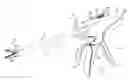
Simultaneous I-beam and spring driven cam jaw closure mechanism
A surgical instrument includes an end effector and a handle assembly. The end effector includes a movable jaw and a cutting element slidably movable within the end effector. The handle assembly includes an energy button configured to deliver energy to at least one electrode located in the end effector, a trigger plate operably coupled to a jaw closure mechanism, the trigger plate configured to close the movable jaw, a firing plate operably coupled to a cutting element drive mechanism. The firing plate is configured to drive the cutting element independently of the jaw closure mechanism. The cutting element drive mechanism is configured to close the movable jaw when the cutting element is driven. The handle assembly further includes a trigger operatively coupled to the trigger plate and the firing plate. The jaw closure mechanism and the cutting element drive mechanism are configured to simultaneously close the movable jaw.
Published: 2016-02-25US20160051316A1
Human necessities
ELECTROSURGICAL ELECTRODE MECHANISM
An electrosurgical instrument comprises a shaft and end effector positioned distally of the shaft. A first jaw comprises a first jaw body, a first jaw energy delivery surface, a first jaw electrode positioned at the first jaw energy delivery surface, an insulator positioned between the first jaw electrode and the first jaw body to thermally insulate the first jaw electrode and the first jaw body, and an inner surface positioned at the first jaw energy delivery surface, thermally coupled to the first jaw body, and electrically coupled to the first jaw body. A second jaw pivotable towards the first jaw from an open position to a closed position comprises a second jaw energy delivery surface. The first jaw energy delivery surface and the second jaw energy delivery surface face one another when the end effector is in the closed position.
Published: 2016-02-25 Assignee: LAM RESEARCH CORPORATION.US20160056074A1
Electricity
Method for void-free cobalt gap fill
Provided herein are methods of depositing void-free cobalt into features with high aspect ratios. Methods involve (a) partially filling a feature with cobalt, (b) exposing the feature to a plasma generated from nitrogen-containing gas to selectively inhibit cobalt nucleation on surfaces near or at the top of the feature, optionally repeating (a) and (b), and depositing bulk cobalt into the feature by chemical vapor deposition. Methods may also involve exposing a feature including a barrier layer to a plasma generated from nitrogen-containing gas to selectively inhibit cobalt nucleation. The methods may be performed at low temperatures less than about 400° C. using cobalt-containing precursors.
Published: 2016-02-25 Assignee: MASIMO CORPORATION.US20160051205A1
Human necessities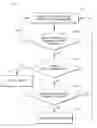
System for determining confidence in respiratory rate measurements
This disclosure describes, among other features, systems and methods for using multiple physiological parameter inputs to determine multiparameter confidence in respiratory rate measurements. For example, a patient monitoring system can programmatically determine multiparameter confidence in respiratory rate measurements obtained from an acoustic sensor based at least partly on inputs obtained from other non-acoustic sensors or monitors. The patient monitoring system can output a multiparameter confidence indication reflective of the programmatically-determined multiparameter confidence. The multiparameter confidence indication can assist a clinician in determining whether or how to treat a patient based on the patient's respiratory rate.
Published: 2016-02-25 Assignee: ASM IP Holding B.V..US20160051964A1
Performing operations; transporting
Method and system for in situ formation of gas-phase compounds
A system and method for providing intermediate reactive species to a reaction chamber are disclosed. The system includes an intermediate reactive species formation chamber fluidly coupled to the reaction chamber to provide intermediate reactive species to the reaction chamber. A pressure control device can be used to control an operating pressure of the intermediate reactive species formation chamber, and a heater can be used to heat the intermediate reactive species formation chamber to a desired temperature.
Published: 2016-02-25 Assignee: INTEL CORPORATION.US20160056156A1
Electricity
Non-planar semiconductor device having doped sub-fin region and method to fabricate same
Non-planar semiconductor devices having doped sub-fin regions and methods of fabricating non-planar semiconductor devices having doped sub-fin regions are described. For example, a method of fabricating a semiconductor structure involves forming a plurality of semiconductor fins above a semiconductor substrate. A solid state dopant source layer is formed above the semiconductor substrate, conformal with the plurality of semiconductor fins. A dielectric layer is formed above the solid state dopant source layer. The dielectric layer and the solid state dopant source layer are recessed to approximately a same level below a top surface of the plurality of semiconductor fins, exposing protruding portions of each of the plurality of semiconductor fins above sub-fin regions of each of the plurality of semiconductor fins. The method also involves driving dopants from the solid state dopant source layer into the sub-fin regions of each of the plurality of semiconductor fins.