Apparatus and method for measuring a nerve diameter
US20050101883A1
2005-05-12
10/980,403
2004-11-02
✅ Patent granted
US 7,044,923 B2
2006-05-16
-
-
Max F. Hindenburg | Rene Towa
2024-11-02
Abstract:
The present invention is generally directed to a nerve measurement apparatus, and to a method for measuring a nerve diameter. In one embodiment, the apparatus comprises an elongated shaft having a first end and an opposing second end, the first end and the second end being suitably configured to determine a diameter of a nerve. The first end may be further comprised of a pair of opposed prongs aligned with a longitudinal axis of the shaft and spaced apart by a predetermined distance to receive the nerve therebetween. The second end may be further comprised of a flexible self-coiling member having an inner diameter that conforms to the nerve diameter when the member is in a relaxed state.
Interested in similar patents?
Get notified when new applications in this technology area are published.
Classification:
A61B5/107 » CPC main
Measuring for diagnostic purposes ; Identification of persons; Detecting, measuring or recording devices for testing the shape, pattern, colour, size or movement of the body or parts thereof, for diagnostic purposes Measuring physical dimensions, e.g. size of the entire body or parts thereof
A61B5/4041 » CPC further
Measuring for diagnostic purposes ; Identification of persons; Detecting, measuring or recording for evaluating the nervous system for evaluating the peripheral nervous systems Evaluating nerves condition
A61B90/06 » CPC further
Instruments, implements or accessories specially adapted for surgery or diagnosis and not covered by any of the groups - , e.g. for luxation treatment or for protecting wound edges Measuring instruments not otherwise provided for
A61B5/6877 » CPC further
Measuring for diagnostic purposes ; Identification of persons; Arrangements of detecting, measuring or recording means, e.g. sensors, in relation to patient specially adapted to be brought in contact with an internal body part, i.e. invasive specially adapted to be attached or implanted in a specific body part Nerve
A61B2090/061 » CPC further
Instruments, implements or accessories specially adapted for surgery or diagnosis and not covered by any of the groups - , e.g. for luxation treatment or for protecting wound edges; Measuring instruments not otherwise provided for for measuring dimensions, e.g. length
A61N1/0551 » CPC further
Electrotherapy; Circuits therefor; Details; Electrodes for implantation or insertion into the body, e.g. heart electrode Spinal or peripheral nerve electrodes
A61B5/103 IPC
Measuring for diagnostic purposes ; Identification of persons Detecting, measuring or recording devices for testing the shape, pattern, colour, size or movement of the body or parts thereof, for diagnostic purposes
A61B5/117 IPC
Measuring for diagnostic purposes ; Identification of persons Identification of persons
Description
CROSS-REFERENCE(S) TO RELATED APPLICATIONThis application claims the benefit of Provisional Application No. 60/519,508, filed Nov. 12, 2003.
TECHNICAL FIELDThe present invention relates generally to the measuring devices, and in particular, to a device for measuring a nerve diameter.
BACKGROUND OF THE INVENTIONMethods for treating and controlling medical, psychiatric or neurological disorders through the application of a modulated electrical signal to a selected nerve or nerve bundle in a patient are well known. Generally, the modulated signal is applied to the nerve or nerve bundle using a neurostimulator electrode assembly that is surgically implanted in the patient. Briefly, and in general terms, the neurostimulator electrode assembly comprises one or more electrodes positioned within a resilient circumneural carrier that is configured to be circumferentially positioned on the nerve. In order for the electrode to establish the requisite electrical contact with the nerve, the carrier must be able to securely hold the electrode against the nerve while not excessively circumferentially compressing the nerve. One example of a neurostimulator electrode assembly is shown and described in U.S. Pat. No. 6,600,956 B2 to Maschino, et al.
In order to accommodate nerves or nerve bundles of various diameters, neurostimulator electrode assemblies are available in standardized sizes that permit a surgeon to select the most appropriate size for implantation in a patient. Currently, the selection of the neurostimulator electrode assembly is made based upon a visual inspection of the nerve diameter. Selection of the electrode assembly by visual inspection has numerous drawbacks, however. If the surgeon selects an electrode assembly that has a diameter that is slightly too large, the electrodes within the assembly may fail to maintain adequate electrical contact with the nerve, as previously mentioned. If an electrode is selected that has a diameter that is too small, a nerve compression injury may result.
In order to overcome the shortcomings present in the visual estimation of a nerve diameter, the nerve diameter may be measured using conventional calipers of suitable size and resolution. Despite this obvious improvement, drawbacks nevertheless still exist. For example, a suitable measurement caliper may not be available to the surgeon while the implantation procedure is occurring. Even if a suitable caliper is available, conventional caliper devices generally possess relatively narrow tips that may cause the relatively compliant nerve to flatten during the measurement, thus rendering an inaccurate nerve diameter measurement.
Therefore, there is a need in the art for an accurate and inexpensive device to accurately measure a nerve diameter in order to achieve a consistent surgical outcome.
SUMMARY OF THE INVENTIONThe present invention is generally directed to a nerve diameter measurement apparatus, and to a method for measuring a nerve diameter. In one aspect, the apparatus comprises an elongated shaft having a first end and an opposing second end, the first end and the second end being suitably configured to determine a diameter of a nerve. The first end may be further comprised of a pair of opposed prongs aligned with a longitudinal axis of the shaft and spaced apart by a predetermined distance to receive the nerve therebetween. The second end may be further comprised of a flexible self-coiling member having an inner diameter that conforms to the nerve diameter when the member is in a relaxed state.
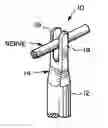
BRIEF DESCRIPTION OF THE DRAWINGSFIG. 1 is a front view and a side view of a nerve measurement apparatus according to an embodiment of the invention.
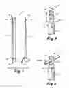
FIG. 2 is an enlarged partial isometric view of one end of a nerve measurement apparatus according to an embodiment of the invention.
FIG. 3 is another partial isometric view of one end of a nerve measurement apparatus according to an embodiment of the invention.
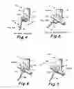
FIG. 4 is a partial isometric view of an opposing end of a nerve measurement apparatus according to an embodiment of the invention.
FIG. 5 is another partial isometric view of an opposing end of a nerve measurement apparatus according to an embodiment of the invention.
FIG. 6 is still another partial isometric view of an opposing end of a nerve measurement apparatus according to an embodiment of the invention.
FIG. 7 is still another partial isometric view of an opposing end of a nerve measurement apparatus according to an embodiment of the invention.
DETAILED DESCRIPTION OF THE INVENTIONThe present invention is generally directed to an apparatus and method for measuring a nerve diameter. Many of the specific details of certain embodiments of the invention are set forth in the following description and in FIGS. 1 to 7 to provide a thorough understanding of such embodiments. One skilled in the art will understand, however, that the present invention may be practiced without several of the details described in the following description. Moreover, in the description that follows, it is understood that the figures related to the various embodiments are not to be interpreted as conveying any specific or relative physical dimension. Instead, it is understood that specific or relative dimensions related to the embodiments, if stated, are not to be considered limiting unless the claims expressly state otherwise.
FIG. 1 is a front view and a side view of a nerve measurement apparatus 10 according to an embodiment of the invention. The apparatus 10 includes an elongated shaft 12 having a first end 14 and a second opposing end 16. The shaft 12 may be formed to have any suitable length L, but in one particular embodiment, the shaft 12 has a length L of approximately about 10 centimeters. Although FIG. 1 depicts the shaft 12 as a substantially straight, elongated member, it is understood that the shaft 12 may include bends or possess an overall curvature in order to allow the apparatus 10 to be more easily manipulated by the surgeon. The shaft 12 may be fabricated from any semi-rigid polymeric material suitable for use in surgical procedures and compatible with conventional sterilization procedures. In addition, the polymeric material comprising the shaft 12 may include a radio-opacifier, such as compounds of barium, or other materials, so that, in the event the apparatus 10 inadvertently remains in a patient's body following an implantation procedure, the shaft 12 may be conveniently imaged using an X-ray procedure. The shaft 12 may also include various color pigments so that the shaft 12 is easily visible. In another particular embodiment, one or more colors may be selected to correspond to a selected nerve diameter, as will be described in greater detail below.
Still referring to FIG. 1, the first end 14 includes a pair of spaced apart prongs that are substantially aligned with a longitudinal axis of the apparatus 10. The first end 14 will be described in greater detail below in connection with another figure. The second end 16 includes a flexible and self-coiling member 20 having a pull tab 18 fixedly attached to the member 20. The second end 16 will also be described in greater detail below in connection with another figure.
FIG. 2 is an enlarged partial isometric view of the a nerve measurement apparatus 10 according to an embodiment of the invention that shows, in particular, the first end 14 of the apparatus 10. As described briefly above, the first end 14 includes a pair of spaced-apart prongs 19 that are substantially aligned with the longitudinal axis of the apparatus 10. In one particular embodiment, the first end 14 has a dimension “a” that is approximately about 2 millimeters, a dimension “b” that is approximately about 8 millimeters, and a dimension “c” that is approximately about 2 millimeters. Referring now to FIG. 3, the prongs 19 are suitably spaced apart and suitably dimensioned to accommodate a nerve between the prongs 19 and to permit a diameter of the nerve to be accurately and rapidly determined.
Turning now to FIGS. 4 and 5, a partial isometric view of the second end 16 of the nerve measurement apparatus 10 according to an embodiment of the invention is shown. The second end 16 includes a self-coiling member 20 that is positioned in a fully-coiled configuration, as shown in FIG. 4, when in a fully relaxed state, and also may be uncoiled by applying a pulling force to the pull tab 18, as shown in FIG. 5. In a particular embodiment, the self-coiling member 20 may have a width “e” of approximately about 3 millimeters, and a diameter “f” of approximately about 2 millimeters when the member 20 is in the relaxed state. When the self-coiling member 20 is in the uncoiled state, a nerve may be positioned adjacent to an interior portion of the member 20. The pulling force on the pull tab 18 may then be relaxed, allowing the member 20 to return to a coiled state and circumferentially surround the nerve. Accordingly, a diameter of a nerve may be made based upon the observed closure of the member 20 about the nerve, as will be discussed in greater detail below. The member 20 may be comprised of any resilient polymeric material capable of sufficient flexure, such as various silicone materials. In one particular embodiment, the member 20 may be formed from SILASTIC, available from the Dow Corning Corp. of Midland, Mich.
Referring now to FIGS. 6 and 7, another partial isometric view of the second end 16 of the nerve measurement apparatus 10 according to an embodiment of the invention is shown. Many of the specific details of the second end 16 have been described in detail above, and in the interests of brevity, will not be described further. Instead, a method for measuring a nerve diameter using the second end 16 will now be described. Referring specifically to FIG. 6, when a nerve is retained within the fully coiled member 20 and an end portion 21 of the member 20 abuts the shaft 12, the diameter of the nerve corresponds to the known inner diameter of the member 20. Thus, the nerve diameter is easily and quickly determined. Referring specifically now to FIG. 7, when a nerve is retained within the fully coiled member 20 and an end portion 21 of the member 20 is spaced apart from the shaft 12 by a distance “g”, it is determined by inspection that the diameter of the nerve is greater than the known inner diameter of the member 20. Accordingly, another apparatus 10 having a member 20 with a larger inner diameter “f” (see FIG. 4) may be selected in order to determine the actual diameter of the nerve.
From the foregoing it will be appreciated that, although specific embodiments of the invention have been described herein for purposes of illustration, various modifications may be made without deviating from the spirit and scope of the invention. For example, certain features shown in the context of one embodiment of the invention may be incorporated into other embodiments as well. Accordingly, the invention is not limited by the foregoing description of embodiments except as by the following claims.
Claims
1. A nerve measurement apparatus, comprising:
a body including a first end and a generally opposing second end, the first end comprising a pair of opposed prongs spaced apart by a predetermined distance to receive a nerve therebetween.
2. The nerve measurement apparatus of claim 1, wherein the second end comprises a flexible self-coiling member that uncoils in response to application of a force thereto and coils to an at least partially relaxed state when the force is removed so that an inner diameter of the flexible self-coiling member generally conforms to an exterior of the nerve when the nerve is received by the flexible self-coiling member.
3. The nerve measurement apparatus of claim 2, wherein the flexible self-coiling member comprises a tab attached thereto.
4. The nerve measurement apparatus of claim 1, wherein the body comprises a polymeric material.
5. The nerve measurement apparatus of claim 2, wherein the flexible self-coiling member comprises a resilient polymeric material.
6. The nerve measurement apparatus of claim 5, wherein the resilient polymeric material comprises silicone.
7. A nerve measurement apparatus, comprising:
a body including a first end and a generally opposing second end, the first end comprising a flexible self-coiling member that uncoils in response to application of a force thereto and coils to an at least partially relaxed state when the force is removed so that an inner diameter of the flexible self-coiling member generally conforms to an exterior of a nerve when the nerve is received by the flexible self-coiling member.
8. The nerve measurement apparatus of claim 7, wherein the second end comprises a pair of opposed prongs spaced apart by a predetermined distance to receive a nerve therebetween.
9. The nerve measurement apparatus of claim 7, wherein the flexible self-coiling member comprises a tab attached thereto.
10. The nerve measurement apparatus of claim 7, wherein the body comprises a polymeric material.
11. The nerve measurement apparatus of claim 7, wherein the flexible self-coiling member comprises a resilient polymeric material.
12. The nerve measurement apparatus of claim 11, wherein the resilient polymeric material comprises silicone.
13. A nerve measurement apparatus, comprising:
an elongated shaft including a first end and a generally opposing second end, the first end including a pair of opposed prongs substantially aligned with a longitudinal axis of the elongated shaft and spaced apart by a predetermined distance to receive a nerve therebetween, the second end including a flexible self-coiling member having a tab attached thereto, the flexible self-coiling member uncoils in response to application of a force to the tab, and the flexible self-coiling member coils to an at least partially relaxed state when the force is removed so that an inner diameter of the flexible self-coiling member generally conforms to an exterior of the nerve when the nerve is received by the flexible self-coiling member.
14. The nerve measurement apparatus of claim 13, wherein the elongated shaft comprises a polymeric material.
15. The nerve measurement apparatus of claim 13, wherein the flexible self-coiling member comprises a resilient polymeric material.
16. The nerve measurement apparatus of claim 15, wherein the resilient polymeric material comprises silicone.
17. A method of measuring a diameter of a nerve, comprising:
providing a nerve measurement apparatus comprising two opposed prongs spaced apart by a fixed predetermined distance; and
inserting the nerve between the two opposing prongs.
18. A method of measuring a diameter of a nerve using a nerve measurement apparatus, the nerve measurement apparatus including a flexible self-coiling member, the flexible self-coiling member being coiled in a relaxed state and at least partially uncoiled in a tensioned state, the method comprising:
uncoiling the flexible self-coiling member;
at least partially enclosing a portion of the nerve with the uncoiled flexible self-coiling member;
allowing the flexible self-coiling member to return to at least a partially relaxed state so that the flexible self-coiling member coils to at least partially enclose the portion of the nerve; and
determining the diameter of the nerve from the extent that the flexible self-coiling member encloses the nerve.
19. The method of claim 18, wherein the act of uncoiling the flexible self-coiling member comprises applying a force to the flexible self-coiling member.
20. The method of claim 18, wherein the act of allowing the flexible self-coiling member to return to at least a partially relaxed state comprises removing a force applied to the flexible coiling member.
21. The method of claim 18, wherein the act of determining the diameter of the nerve comprises determining a distance that an end portion of the flexible self-coiling member is offset from a reference position when the flexible self-coiling member is in the relaxed state.
Images & Drawings included:
Sources:
- United States Patent and Trademark Office - verify current appl. status at the USPTO↗
Recent applications in this class:
- » 20250204808 2025-06-26
A METHOD AND A SYSTEM FOR MONITORING A TREATMENT AREA OF A PATIENT - » 20250194951 2025-06-19
BODY MAP CREATION DEVICE AND BODY MAP CREATION METHOD - » 20250009256 2025-01-09
CUSTOM PATIENT INTERFACE AND METHODS FOR MAKING SAME - » 20240398256 2024-12-05
BODY PART DIMENSION MEASURING APPAREL AND METHOD OF USE - » 20240081680 2024-03-14
Acoustic wave measurement apparatus and operation method of acoustic wave measurement apparatus - » 20240074675 2024-03-07
Adaptive ultrasound scanning - » 20240049985 2024-02-15
METHODS OF SELECTING SURGICAL IMPLANTS AND RELATED DEVICES - » 20240041350 2024-02-08
SYSTEMS AND METHODS FOR INTRA-OPERATIVE PELVIC REGISTRATION - » 20230200680 2023-06-29
Systems and method for scanning subjects to ascertain body measurements - » 20230128461 2023-04-27
INFORMATION PROCESSING APPARATUS AND COMPUTER-READABLE MEDIUM