Raised access floor structure for networks
US20050102936A1
2005-05-19
10/698,420
2003-11-03
Abstract:
The raised access floor structure for networks comprises: a plurality of floor units and a plurality of supporting seats; wherein each of the supporting seats is composed of a crossed member and four pedestals integrally connecting therewith; the crossed member is located lower than the tops of the pedestals, and has between every two neighboring pedestals at least a separating piece; thereby, four floor units separated mutually have their positions limited by the separating pieces after folded flanks of the floor units are received in the crossed member, and the floor units can be clung evenly on the tops of the pedestals. The structure is applied to use for network-line laying out in a house or in an office etc.
Interested in similar patents?
Get notified when new applications in this technology area are published.
Classification:
E04F15/02488 » CPC main
Flooring; Flooring or floor layers composed of a number of similar elements; Sectional false floors, e.g. computer floors; Supporting structures; Height adjustable elements for supporting the panels or a panel-supporting framework filled with material hardening after application
E04F15/02405 » CPC further
Flooring; Flooring or floor layers composed of a number of similar elements; Sectional false floors, e.g. computer floors Floor panels
E04F15/02447 » CPC further
Flooring; Flooring or floor layers composed of a number of similar elements; Sectional false floors, e.g. computer floors Supporting structures
Description
BACKGROUND OF THE INVENTION1. Field of the Invention
The present invention is related to a raised access floor structure for networks, and especially to a raised access floor structure that is structurally simple, stead and easy for positioning after assembling, not subject to an uneven ground and having good grounding effect; it is applied to use for network-line laying out in a house or in an office etc.
2. Description of the Prior Art
Distribution and laying out of networks and other kind of lines are very important and necessary in modern life. Because that every computer can only be connected with a host or connected electrically through a network, so that intertwining of lines becomes more and more complicated when amount of equipment gets larger and larger. If lines are exposed outside, they look badly and affect walking of people.
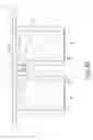
A floor for networks can be elevated for assembling, it leaves a space for threading and distribution of lines; thereby it has been of the main trend for datalization of modern office. Related raised access floors for networks in the markets presently have much improvement upon those raised access floors developed in the initial stage, and there are various kinds of products. Referring to FIGS. 8-9 showing a conventional raised access floor structure for networks, the floor includes a plurality of floor units A and a plurality of raising seats B (the raising seats B can be of the specification as shown in FIG. 8). Wherein the four peripheral edges of each floor unit A are folded down to form folded flanks A1; the top surface of each raising seat B has a crossed slit B1, each crossed slit B1 can receive therein two folded flanks A1 formed on two floor units A. By the fact that each raising seat B can be used to raise a corner of each of four floor units A, in this way, a large raised access floor for networks can be formed.
In fact, designing of a raised access floor for networks with good quality, in addition to being easy for mold opening and production, shall have the consideration of the convenience in arrangement and positioning in construction in site as well as of the acquiring of stable supporting of the floor units after assembling without being subject to shaking and an uneven ground. However, although the aforesaid raised access floor for networks can achieve its object of use, it still has the following flaws:
- 1. Its raising seats are each integrally formed to have a fixed appearance; they cannot be adjusted in pursuance of the unevenness of a ground. When the ground is uneven, the seats tend to get upwardly bending corners; and if the ground is recessed, a case that the floor units are hard to insert for being received can be induced.
- 2. Each slit on a raising seat shall have a width to make tight mating of two folded flanks on two floor units therein, this makes a situation that insertion of only one folded flank may induce loosening that renders the second folded flank hard to insert. Similarly, when floor units are removed for repairing or line distribution afterwards, lifting of a floor unit will make loosening and displacement of the neighboring floor unit relative to its corresponding seat, this renders construction inconvenient and accuracy of construction largely reduced.
- 3. Electric grounding of the floor units can only be achieved by mutual contact of the surfaces of the ground with the floor units after engaging of the folded flanks in the slits, as stated above, the ground is not completely even, and the thickness of each floor unit is not completely precise nor uniform, the entire structure after assembling is subject to shaking, thereby grounding effect is not ideal. Especially in those countries using 220 volts electrically, it is unable to make suitable dealing with grounding.
In view of these, the inventors of the present invention developed a raised access floor structure for networks based on their professional experience of years on raised access floors to solve the above stated problems.
SUMMARY OF THE INVENTIONThe primary objective of the present invention is to provide a raised access floor structure that is not subject to an uneven ground, and is structurally simple, stead and easy for positioning after assembling.
The secondary objective of the present invention is to provide a raised access floor structure which is good in grounding and can increase the strength of supporting structurally.
Another objective of the present invention is to provide a raised access floor structure that is easy for drawing out lines.
To achieve the above stated objectives, the raised access floor structure of the present invention comprises: a plurality of floor units and a plurality of supporting seats.
In the present invention, the four peripheral edges of each floor unit are folded down to form folded flanks; each supporting seat is located beneath the center of four mutually neighboring floor units to support the four floor units. The present invention is characterized by that: each supporting seat is composed of a crossed member and four pedestals integrally connecting therewith; the crossed member is located lower than the tops of the pedestals, and has between every two neighboring pedestals at least a separating piece.
Thereby, the four floor units can be separated mutually to have their positions limited by the separating pieces after the folded flanks of the floor units are received in the crossed member, and the floor units can be clung evenly on the tops of their corresponding pedestals.
The present invention will be apparent after reading the detailed description of the preferred embodiment thereof in reference to the accompanying drawings.
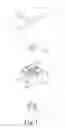
BRIEF DESCRIPTION OF THE DRAWINGSFIG. 1 is an exploded perspective view showing the appearance of the embodiment of the present invention;
FIG. 2 is a side view showing the state after floor units are placed in a supporting seat of the embodiment of the present invention;
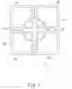
FIG. 3 is a top view of the supporting seat of the embodiment of the present invention;
FIG. 4 is a schematic plan view showing part of the appearance of the embodiment of the present invention after assembling;
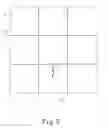
FIG. 5 is schematic plan view showing conveniently drawing a line under two floor units juxtaposed with each other out of a slot formed between the floor units of the embodiment of the present invention;
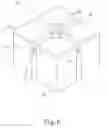
FIG. 6 is a perspective view showing the appearance of the supporting seat of the present invention having a pole protruding upwardly from a central crossed member;
FIG. 6A is a sectional view taken from FIG. 6, showing light cement is filled in pedestals of the supporting seat.
DETAILED DESCRIPTION OF THE PREFERRED EMBODIMENTReferring firstly to FIGS. 1-5 showing a preferred embodiment of the raised access floor structure for networks of the present invention, the structure comprises: a plurality of floor units 1 and a plurality of supporting seats 2.
Each of the floor units 1 has four peripheral edges folded down to form folded flanks 11.
The supporting seats 2 are integrally made of PE or plastic material. Each supporting seat 2 is located beneath the center of four mutually neighboring floor units 1 to support the latter. Such a supporting seat 2 is composed of a crossed member 21 and four pedestals 22 integrally connecting therewith; the crossed member 21 is located lower than the tops of the pedestals 22, and has between every two neighboring pedestals 22 a separating piece 211.
Thereby, the four floor units 1 can be separated mutually to have their positions limited by the separating pieces 211 after the folded flanks 11 of the floor units 1 are received in the crossed member 21, and the floor units 1 can be clung evenly on the tops of their corresponding pedestals 22. So that easy assembling can be attained, and no loosening or hard receiving during assembling can occur.
Referring again to FIGS. 1-5, when in practicing, the middle sections of the separating pieces 211 can be interrupted (as shown in FIG. 3) in favor of easy insertion of the floor units 1. Each floor unit 1 has on its one peripheral edge an arciform notch 13, so that when two arciform notches 13 of two floor units 1 are juxtaposed with each other, a line outlet 4 is formed (as shown in FIGS. 4, 5). Two “L” shaped stop pieces 212 are provided respectively at the two lateral sides of each of the separating pieces 211 for firm positioning of the floor units 1.
Referring simultaneously to FIGS. 1, 3, wherein each pedestal 22 is hollow; and the supporting seat 2 can be inserted therein with a metal post 4 for reinforcement in supporting. The metal post 4 is cylindrical, and has a plurality of notches 41 spaced away mutually to form a castle-like form. The diagonally opposite four corners of the four pedestals 22 of the supporting seat 2 can be changed to form arciform corner walls 221 to encircle a round space, this can allow insertion of the metal post 4 from below the supporting seat 2. Thereby, the supporting seat 2 can be added therein with the metal post 4 during assembling, this not only can increase firmness of the supporting seat 2, but also can increase the fireproof effect by having the metal material.
In addition, to meet the requirement of those countries using 220 volts electrically in grounding, the supporting seat 2 provided in the present invention can be covered with a grounding metal pad-piece 23 on the crossed member 21 of the supporting seat 2 when in manufacturing in a factory (as shown in FIGS. 1, 2), hence in construction, when the floor units 1 are placed in the supporting seat 2, the floor units 1 can be directly pressed upon the grounding metal pad-piece 23 to make grounding of the floor units 1 through the grounding metal pad-piece 23.
As shown in FIGS. 1-5, when in laying out, the metal post 4 is placed from below the supporting seat 2 to render the crossed member 21 in the supporting seat 2 to be abutted against and fixed on the notches 41 of the metal post 4. Then the supporting seat 2 is well placed on the ground, and the floor units 1 can be inserted one by one in the crossed member 21 in the supporting seat 2 (the arciform notches 13 of the floor units 1 all direct to the same center). When in insertion of a floor unit 1, its peripheral folded flanks 11 are limited between their corresponding separating pieces 211 and pedestals 22 to avoid inconvenience of insertion of other floor units 1 induced by loosening of the first floor unit 1. And insertion of the floor units 1 can directly press upon the grounding metal pad-piece 23, so that the floor units 1 can make grounding through the grounding metal pad-piece 23. When an electrician works in construction, he may make grounding at any of the floor units 1 at a suitable location.
After assembling, if it is desired to repair, a tool can be used to pry a floor unit 1 taking advantage of a corresponding arciform notch 13. And during line distribution, an arciform notch 13 of a floor unit 1 can be changed in direction to make another arciform notch 13 of another floor unit 1 opposite thereto to form a hole 14 (as shown in FIG. 5), this helps to drawing out lines thereunder.
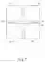
Further referring to FIGS. 6-7, to make a better fireproof effect to reach the “0” class fireproof standard, every pedestal 22 can be filled therein with light cement 5, and the bottom of the pedestal 22 can be tightly sealed with an adhesive coating 6, in order that the pedestal 22 can be a closed solid member.
Besides, for the purpose of rendering a grounding metal pad-piece 23 more stably placed on a supporting seat 2, the crossed member 21 in the supporting seat 2 can be provided with a pole 24 protruding upwardly from a central crossed member 21 of the supporting seat 2 for fixedly engaging of the grounding metal pad-piece 23 thereon; the pole 24 is further provided thereon with a locking hole 241.
In summary, the present invention thereby has the following advantages:
- 1. The raised access floor structure for networks of the present invention is simple structurally and easy for assembling. With the design of separating pieces, even a single one floor unit can make the structure fixed when it is inserted in, and its corresponding supporting seat will not be loosened to affect assembling of another floor unit. The entire structure is very firm after assembling. And in practical distribution in construction, thickness of the separating pieces is very thin, and the floor will be added with articles such as rectangular blankets etc. after construction, no worry is supposed to have about something will drop or be blocked by the separating pieces.
- 2. Each supporting seat of the present invention is composed of a crossed member and four pedestals integrally connecting therewith; hence the entire structure is softer and more flexible, the crossed member and four pedestals are connected mutually but not completely fixed nor inflexible, the structure can be adjusted by slightly bending in pursuance of unevenness of a ground to facilitate assembling in construction.
- 3. Each supporting seat of the present invention is provided therein with a cylindrical metal post to largely increase the firmness of the supporting seat. And the metal material can increase the fireproof effect of the supporting seat. Alternatively, each pedestal can be filled therein with light cement, and the bottom of the pedestal can be tightly sealed with an adhesive coating to get a even better fireproof effect to reach the “0” class fireproof standard.
- 4. Each supporting seat of the present invention is covered with a grounding metal pad-piece on the crossed member of the supporting seat when manufacturing in a factory, hence in construction, floor units can be directly pressed upon the grounding metal pad-piece to make ground contacting of the floor units. There is no need of other construction for grounding, thereby it is very convenient and time saving in construction.
- 5. When in assembling the floor, and during line distribution, it needs only to change the direction of an arciform notch of a floor unit to be opposite to another arciform notch of another floor unit to form a hole, this is benefit to drawing out lines thereunder.
The embodiment given is only for illustrating the present invention, and not for giving any limitation to the scope of the present invention. It will be apparent to those skilled in this art that various modifications or changes without departing from the spirit of this invention shall also fall within the scope of the appended claims.
In conclusion, the present invention can get the expected objectives thereof to provide a practicable raised access floor structure for networks. Having thus described my invention, what we claim as new and desire to be secured by Letters Patent of the United States are:
Claims
1. A raised access floor structure for networks, said structure comprises:
a plurality of floor units, each of said floor units has four peripheral edges folded down to form folded flanks;
a plurality of supporting seats, each of said supporting seat is located beneath the center of four mutually neighboring ones of said floor units to support the latter; said structure is characterized by that: each of said supporting seats is composed of a crossed member and four pedestals integrally connecting therewith; said crossed member is located lower than tops of said pedestals, and has between every two neighboring ones of said pedestals at least a separating piece; thereby, said four floor units are separated mutually to have their positions limited by said separating pieces after said folded flanks of said floor units are received in said crossed member, and said floor units are clung evenly on said tops of the corresponding ones of said pedestals.
2. The raised access floor structure for networks as in claim 1, wherein said supporting seats are integrally made of plastic material.
3. The raised access floor structure for networks as in claim 1, wherein middle sections of said separating pieces are interrupted.
4. The raised access floor structure for networks as in claim 1, wherein said supporting seats each is covered with a grounding metal pad-piece on said central crossed member thereof, when said floor units are placed in said supporting seat, said floor units make electric grounding through said grounding metal pad-piece.
5. The raised access floor structure for networks as in claim 4, wherein said central crossed member in said supporting seat is provided with a upwardly protruding pole for fixedly engaging of said grounding metal pad-piece thereon; said pole is further provided thereon with a locking hole.
6. The raised access floor structure for networks as in claim 1, wherein two “L” shaped stop pieces are provided respectively at two lateral sides of each of said separating pieces for firm positioning of said floor units.
7. The raised access floor structure for networks as in claim 1, wherein every pedestal is filled therein with light cement, and the bottom of said pedestal is tightly sealed with an adhesive coating, in order that said pedestal is a closed solid member.
8. The raised access floor structure for networks as in claim 1, wherein each of said pedestals is hollow; and each of said supporting seats is inserted therein with a metal post for reinforcement in supporting.
9. The raised access floor structure for networks as in claim 8, wherein said metal post is cylindrical, and has a plurality of notches spaced away mutually on the top of said metal post; four diagonally opposite corners of said four pedestals of said supporting seat form arciform corner walls to encircle a round space, when in insertion of said metal post from below said supporting seat, said crossed member is abutted against and fixed on notches provided on said metal post.
10. The raised access floor structure for networks as in claim 1, wherein each of said floor units has on one peripheral edge thereof an arciform notch, so that when two of said arciform notches of two of said floor units are juxtaposed with each other, a line outlet is formed.
Images & Drawings included:


Sources:
- United States Patent and Trademark Office - verify current appl. status at the USPTO↗
Similar patent applications:
- » 20050076590
Structure of raised access floor for networks