Mounting apparatus for circuit board
US20050106936A1
2005-05-19
10/982,424
2004-11-05
✅ Patent granted
US 6,964,581 B2
2005-11-15
-
-
Tho D. Ta | Larisa Tsukerman
2024-11-05
Abstract:
A mounting apparatus for a circuit board (10) comprises a support plate (50), a tray (20) and a clip (40). The support plate includes a plurality of catches (52) and two locking holes (56). The tray for positioning the circuit board thereon defines a plurality of catch apertures (26). The tray includes a bent plate (22) extending upwardly from a rear side. The clip is pivotally mounted to the tray. The clip includes a locking portion (42) having two protrusions (422), and an operation portion (46) having two resilient fingers (462) pressing the bent plate. In assembly, the catches of the support plate slidably engage in the catch apertures of the tray, the protrusions of the clip extend in the locking hole of the support plate to secure the circuit board to the support plate.
Assignee:
- Hon Hai Precision Ind. Co., Ltd. 1,929 🇹🇼 Taipei Hsien, Taiwan
Interested in similar patents?
Get notified when new applications in this technology area are published.
Classification:
H05K7/1417 » CPC main
Constructional details common to different types of electric apparatus; Mounting supporting structure in casing or on frame or rack having securing means for mounting boards, plates or wiring boards
H05K7/1417 » CPC main
Constructional details common to different types of electric apparatus; Mounting supporting structure in casing or on frame or rack having securing means for mounting boards, plates or wiring boards
Description
BACKGROUND OF THE INVENTION1. Field of the Invention
The present invention relates to mounting apparatuses, and particularly to a mounting apparatus for readily and securely mounting a circuit board therein.
2. Description of the Related Art
During assembly of a typical personal computer, a circuit board must be fastened to a computer frame or chassis. The circuit board is conventionally mounted to the computer chassis using fasteners such as screws or bolts. However, when installing or removing the circuit board, using the fasteners is laborious and time-consuming. In addition, a tool such as a screwdriver or wrench is usually required. Moreover, the circuit board is prone to be damaged if the tool slips during manipulation of the fasteners.
Taiwan Pat. No. 551,026 discloses a mounting apparatus for a circuit board. The circuit board is firstly secured to a tray using fasteners such as clips. The clips engage in corresponding through holes of the tray to secure the circuit board thereon. Then the combined circuit board and tray is mounted to a computer chassis. A tool is not required when using the clips. However, the using of the clips increases the cost of the manufacture. Because the clips are not conventional components, it is inconvenient when some clips destroyed or missing.
Thus, an improved mounting apparatus for circuit boards which overcomes the above-mentioned problems is desired.
BRIEF SUMMARY OF THE INVENTIONAccordingly, an object of the present invention is to provide a mounting apparatus for readily and securely installing and removing a circuit boards to and from equipment such as a chassis of a computer.
To achieve the above object, the mounting apparatus for a circuit board of the present invention comprises a support plate, a tray and a clip. The support plate includes a plurality of catches and two locking holes. The tray for positioning the circuit board thereon defines a plurality of catch apertures. The tray includes a bent plate extending upwardly from a rear side. The clip is pivotally mounted to the tray. The clip includes a locking portion having two protrusions, and an operation portion having two resilient fingers pressing the bent plate. In assembly, the catches of the support plate slidably engage in the catch apertures of the tray, the protrusions of the clip extend in the locking hole of the support plate to secure the circuit board to the support plate.
Other objects, advantages and novel features of the present invention will become more apparent from the following detailed description when taken in conjunction with the accompanying drawings, in which:
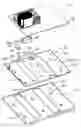
BRIEF DESCRIPTION OF THE DRAWINGSFIG. 1 is an exploded, isometric view of a motherboard mounting apparatus in accordance with the preferred embodiment of the present invention, together with a circuit board, the mounting apparatus comprising a tray, a clip, a fixing means and a support plate;
FIG. 2 is an isometric view of the clip of FIG. 1, but viewed from another aspect;
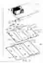
FIG. 3 is an assembled view of FIG. 1;
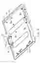
FIG. 4 is similar to FIG. 3 without the circuit board, with the tray in a locked position; and
FIG. 5 is similar to FIG. 3 without the circuit board, with the tray in an unlocked position.
DETAILED DESCRIPTION OF THE INVENTIONReferring to FIGS. 1 and 2, a mounting apparatus in accordance with the preferred embodiment of the present invention is used to accommodate a circuit board 10 therein. A plurality of through holes 12 is defined in the circuit board 10. The mounting apparatus comprises a tray 20, a fixing means 24, a clip 40 and a support plate 50. The support plate 50 is to be attached to a panel of a computer chassis (not shown).
The support plate 50 comprises a plurality of spaced catches 52 which is stamped upwardly from it. Each catch 52 comprises a generally horizontal portion, and a neck 53 connecting between the horizontal portion and the support plate 50. A pair of guiding posts 54 protrudes from the support plate 50 at one side. A pair of locking holes 56 is defined at a rear side of the support plate 50.
The tray 20 comprises a bent plate 22 extending upwardly from a rear edge thereof. A plurality of standoffs 29 protrudes from the tray 20, corresponding to the through holes 12 of the circuit board 10. A plurality of catch apertures 26 is defined in the tray 20, corresponding to the catches 52 of the support plate 50. Each catch aperture 26 comprises a wide guiding part 261 and a narrow locking part 263 toward the bent plate 22 and in communication with the guiding part 261. A pair of guiding slots 28 is defined in the tray 20, corresponding to the guiding posts 54 of the support plate 50. A pair of through apertures 36 is defined in the tray 20 adjacent to the bent plate 22, corresponding to the locking holes 56 of the support plate 50. A tab 32 is stamped upwardly from the tray 20 between the bent plate 22 and one through apertures 36. The tab 32 defines a pivot hole 322. A retaining hole 38 and a screw hole 39 are defined in the tray 20 between the bent plate 22 and the other through apertures 36.
The clip 40 has a generally L shape. The clip 40 comprises a locking portion 42, an operation portion 46, and an axis 44 connecting the locking portion 42 and the operation portion 46. A pair of protrusions 422 protrudes downwardly from a front portion of the locking portion 42, corresponding to the locking holes 56 of the support plate 50, and the through aperture 36 of the tray 20. A pair of resilient fingers 462 is stamped outwardly from the operation portion 46.
The fixing means 24 has a horizontal part and a vertical part. A splint 241 is bent from a distal end of the horizontal part at 180 degree. A screw hole 243 is defined in the horizontal part, corresponding to the screw hole 39 of the tray 20. A pivot hole 242 is defined in the vertical part, corresponding to the pivot hole 322 of the tray 20.
Referring to FIGS. 3-5, when assembling the clip 40 and the fixing means 24 to the tray 20, one end of the axis 44 of the clip 40 is inserted in the pivot hole 322 of the tray 20. The protrusions 422 of the clip 40 extend through the through aperture 36 of the tray 20. The splint 241 of the fixing means 24 extends through the retaining hole 38 of the tray 20 and clips the tray 20, with the pivot hole 242 receiving the other end of the axis 44 of the clip 40. A screw (not shown) extends through the screw hole 243 of the fixing means 24 and engages in the screw hole 39 of the tray 20. The tray 20, the fixing means 24 and the clip 40 are assembled together. Meanwhile, the resilient fingers 462 of the clip 40 are elastically pressing on the bent plate 22 of the tray 20.
When assembling the circuit board 10 to the tray 20, the standoffs 29 of the tray 20 extends through the corresponding through holes 12 of the circuit board 10 and engage therein. Thus, the circuit board 10 is assembled to the tray 20.
The combined circuit board 10, tray 20, fixing means 24 and clip 40 is placed on the support plate 50. The catches 52 of the support plate 50 are extended into the guiding parts 261 of the catch apertures 26 of the tray 20. The bent plate 22 of the tray 20 is pushed forwardly, so that the necks 53 of the catches 52 are slid into the locking parts 263 of the catch apertures 26 respectively. The protrusions 422 of the clip 40 are engaged snappingly in the locking holes 56 of the support plate 50 respectively. Thus, the circuit board 10 is secured in the chassis.
To remove the circuit board 10 from the chassis, the clip 40 pivots toward the bent plate 22 around the axis 44 by pushing the operation portion 46, with the resilient fingers 462 being elastically compressed. The protrusions 422 are withdrawn from the locking holes 56 of the support plate 50 respectively. The bent plate 22 of the tray 20 is pushed backwardly to slide the necks 53 of the catches 52 of the support plate 50 from the locking parts 263 to the guiding part 261 of the catch apertures 26. The combined circuit board 10, tray 20, fixing means 24 and clip 40 is then easily removed from the chassis.
Alternatively, the tray 20 can be secured to the support plate 50 firstly, then the motherboard 10 is mounted to the tray 20. The catches 52 can be formed on the tray 20 and the catch apertures 26 can be defined in the support plate 50. In addition, the support plate 50 can be the panel of the chassis, that is, the catches 52, the guiding parts 54 and locking holes 56 can be directly formed at the panel of the chassis.
While the present invention has been illustrated by the description of the preferred embodiment thereof, and while the preferred embodiment has been described in considerable detail, it is not intended to restrict or in any way limit the scope of the appended claims to such detail. Additional advantages and modifications within the spirit and scope of the present invention will readily appear to those skilled in the art. Therefore, the present invention is not limited to the specific details and illustrative examples shown and described.
Claims
1. A mounting apparatus for a circuit board, comprising:
a support plate comprising a plurality of catches, a locking hole defined in the support plate;
a tray adapted for positioning the circuit board thereon, the tray defining a plurality of catch apertures and a through aperture, and the tray comprising a bent plate extending upwardly thereform; and
a clip pivotally mounted to the tray, the clip comprising a first portion and a second portion, the first portion comprising a protrusion extending downwardly therefrom, the second portion comprising a resilient means elastically pressing on the bent plate of the tray;
wherein the catches of the support plate slidably engage in the catch apertures of the tray, the protrusion of the clip extends through the through hole of the tray and engages in the locking hole of the support plate to secure the circuit board to the support plate.
2. The mounting apparatus as claimed in claim 1, wherein the bent plate extends upwardly from a rear side of the tray.
3. The mounting apparatus as claimed in claim 1, wherein the tray comprises a tab stamped upwardly from a rear side of the tray and defines a pivot hole therein.
4. The mounting apparatus as claimed in claim 1, wherein the tray comprises a fixing means that has a horizontal part and a vertical part.
5. The mounting apparatus as claimed in claim 4, wherein a splint is bent at 180 degree from a distal end of the horizontal part of the fixing means.
6. The mounting apparatus as claimed in claim 5, wherein a pivot hole is defined in the vertical part of the fixing means.
7. The mounting apparatus as claimed in claim 1, wherein each of the catch apertures comprises a guiding part and a locking part, each of the catches comprises a generally horizontal portion and a neck connecting between the horizontal portion and the support plate.
8. The mounting apparatus as claimed in claim 1, wherein the tray comprises a plurality of standoffs for supporting the circuit board.
9. The mounting apparatus as claimed in claim 1, wherein the protrusion protrudes downwardly from a distal end of the first portion, the resilient means is stamped outwardly from the second portion.
10. A mounting apparatus for a circuit board, comprising:
a support plate defining a locking hole therein, and comprising a pair of guiding posts thereon;
a tray adapted for positioning the circuit board thereon, and comprising a bent plate extending upwardly from the tray, the tray defining a through hole and a pair of guiding slots therein; and
a clip pivotally mounted to the tray, and comprising a first portion and a second portion, the first portion comprising a protrusion extending downwardly therefrom, the second portion comprising a resilient means pressing the bent plate of the tray;
wherein the guiding posts of the support plate slidably engage in the guiding slots of the tray, the protrusion of the clip extends through the through hole of the tray and engages in the locking hole of the support plate to secure the tray to the support plate.
11. The mounting apparatus as claimed in claim 10, wherein the support plate comprises a plurality of catches which is stamped upwardly from the support plate.
12. The mounting apparatus as claimed in claim 11, wherein the tray comprises a plurality of catch apertures corresponding to the catches.
13. The mounting apparatus as claimed in claim 12, wherein each of the catch apertures comprises a guiding part and a locking part.
14. The mounting apparatus as claimed in claim 10, wherein the tray comprises a tab stamped upwardly from a rear side of the tray defining a pivot hole therein.
15. The mounting apparatus as claimed in claim 10, wherein the tray comprises a fixing means that has a horizontal part and a vertical part.
16. The mounting apparatus as claimed in claim 15, wherein a splint is bent at 180 degree from a distal end of the horizontal part of the fixing means.
17. The mounting apparatus as claimed in claim 16, wherein a pivot hole is defined in the vertical part of the fixing means.
18. The mounting apparatus as claimed in claim 10, wherein the protrusion protrudes downwardly from a distal end of the first portion, the resilient means is stamped outwardly from the second portion.
19. A mounting apparatus assembly comprising:
a fixed support plate;
a tray detachably fastened to the support plate;
a mother board detachably attached to the tray;
an interengagement device formed on both said support plate and said tray which allows the tray to initially downwardly approach the support plate vertically, and successively move horizontally to a final locked position where said tray can no longer move vertically, wherein
a clip pivotally mounted to the tray and defining a locking head extending through the tray and latched to the support plate for preventing backward horizontal movement of the tray relative to the support plate from the locked position when said clip is in a first pivotal position while allowing said backward horizontal movement when said clip is in a second pivotal position.
20. The assembly as claimed in claim 19, wherein said clip is located around an edge area of the tray.
Images & Drawings included:


Sources:
- United States Patent and Trademark Office - verify current appl. status at the USPTO↗
Similar patent applications:
- » 20140153202
CIRCUIT BOARD MOUNTING APPARATUS - » 20140321081
CIRCUIT BOARD MOUNTING APPARATUS - » 20140003020
CIRCUIT BOARD MOUNTING APPARATUS - » 20140146502
CIRCUIT BOARD MOUNTING APPARATUS - » 20140153207
CIRCUIT BOARD MOUNTING APPARATUS - » 20140157589
Circuit board mounting apparatus - » 20130044449
Circuit board mounting apparatus - » 20130329387
CIRCUIT BOARD MOUNTING APPARATUS - » 20140140024
CIRCUIT BOARD MOUNTING APPARATUS - » 20240105643
CIRCUIT BOARD, IMAGE FORMING APPARATUS, MOUNTING METHOD ONTO CIRCUIT BOARD, AND METHOD OF MANUFACTURING PLURALITY OF IMAGE FORMING APPARATUS
Recent applications in this class:
- » 20250287521 2025-09-11
LOCKING DEVICE AND LOCKING STRUCTURE USING SAME - » 20250234472 2025-07-17
SYSTEMS AND METHODS FOR LOW-PROFILE COUPLING OF AN INFORMATION HANDLING RESOURCE TO AN INFORMATION HANDLING SYSTEM CHASSIS - » 20250024623 2025-01-16
CONNECTION MECHANISM AND DISPLAY DEVICE - » 20240407121 2024-12-05
MAIN BOARD ASSEMBLY - » 20240389257 2024-11-21
MOUNTING BRACKET AND ELECTRONIC DEVICE AND DISPLAY APPARATUS INCLUDING THE SAME - » 20240389256 2024-11-21
IMAGING APPARATUS - » 20240284626 2024-08-22
Chassis ear apparatus and mounting method thereof - » 20240276667 2024-08-15
FIXING STRUCTURE OF CIRCUIT BOARD AND PUMP DEVICE - » 20240268053 2024-08-08
RISER CAGE FASTENERS FOR AN INFORMATION HANDLING SYSTEM - » 20240268052 2024-08-08
Sliding latch for retention of peripheral device
Recent applications for this Assignee:
- » 20110045702 2011-02-24
Electrical cable connector assembly with improved wire organizer - » 20110021088 2011-01-27
Electrical connector with improved contact footprints - » 20110021082 2011-01-27
High density backplane connector having improved terminal arrangement - » 20110008982 2011-01-13
N-in-1 card connector - » 20110005825 2011-01-13
Cable assembly with EMI protection - » 20110003508 2011-01-06
Electrical connector rotatably mounted to a portable device - » 20100330822 2010-12-30
Electrical connector having contact with upper terminal and lower terminal - » 20100317218 2010-12-16
Electrical connector assembly with latching mechanism - » 20100297861 2010-11-25
Socket connector having improved actuating mechanism for driving moving plate - » 20100291799 2010-11-18
Shielded connector with enlarged base supporting cantilevered brackets extending from the shielded connector