Manufacture of insulation
US20050139335A1
2005-06-30
10/409,830
2003-04-08
Abstract:
Improvements in the catalytic processing of organic compounds for fuels and for other uses, and ways in order to better utilize the heat from the above processing and also from other sources.
Interested in similar patents?
Get notified when new applications in this technology area are published.
Classification:
C10J3/08 » CPC main
Production of combustible gases containing carbon monoxide from solid carbonaceous fuels; Fixed-bed gasification of lump fuel; Continuous processes with ash-removal in liquid state
B01D45/16 » CPC further
Separating dispersed particles from gases or vapours by gravity, inertia, or centrifugal forces by centrifugal forces generated by the winding course of the gas stream, the centrifugal forces being generated solely or partly by mechanical means, e.g. fixed swirl vanes
B03C3/017 » CPC further
Separating dispersed particles from gases or vapour, e.g. air, by electrostatic effect Combinations of electrostatic separation with other processes, not otherwise provided for
B03C3/145 » CPC further
Separating dispersed particles from gases or vapour, e.g. air, by electrostatic effect; Plant or installations having external electricity supply dry type characterised by the additional use of mechanical effects, e.g. gravity Inertia
C10G11/04 » CPC further
Catalytic cracking, in the absence of hydrogen, of hydrocarbon oils characterised by the catalyst used Oxides
C10J3/16 » CPC further
Production of combustible gases containing carbon monoxide from solid carbonaceous fuels; Fixed-bed gasification of lump fuel; Continuous processes simultaneously reacting oxygen and water with the carbonaceous material
C10J3/30 » CPC further
Production of combustible gases containing carbon monoxide from solid carbonaceous fuels; Fixed-bed gasification of lump fuel; Apparatus; Plants Fuel charging devices
C10J3/34 » CPC further
Production of combustible gases containing carbon monoxide from solid carbonaceous fuels; Fixed-bed gasification of lump fuel; Apparatus; Plants Grates; Mechanical ash-removing devices
C10J2200/158 » CPC further
Details of gasification apparatus; Details of feeding means Screws
C10J2300/0916 » CPC further
Details of gasification processes; Details of the feed, e.g. feeding of spent catalyst, inert gas or halogens; Carbonaceous raw material Biomass
C10J2300/0946 » CPC further
Details of gasification processes; Details of the feed, e.g. feeding of spent catalyst, inert gas or halogens; Carbonaceous raw material Waste, e.g. MSW, tires, glass, tar sand, peat, paper, lignite, oil shale
C10J2300/0956 » CPC further
Details of gasification processes; Details of the feed, e.g. feeding of spent catalyst, inert gas or halogens; Gasifying agents Air or oxygen enriched air
C10J2300/0959 » CPC further
Details of gasification processes; Details of the feed, e.g. feeding of spent catalyst, inert gas or halogens; Gasifying agents Oxygen
C10J2300/0969 » CPC further
Details of gasification processes; Details of the feed, e.g. feeding of spent catalyst, inert gas or halogens; Gasifying agents Carbon dioxide
C10J2300/1634 » CPC further
Details of gasification processes; Integration of gasification processes with another plant or parts within the plant with solids treatment; Ash post-treatment Ash vitrification
C10J2300/1823 » CPC further
Details of gasification processes; Details of the gasification process, e.g. loops, autothermal operation; Recycle loops, e.g. gas, solids, heating medium, water for synthesis gas
Y02P20/129 » CPC further
Technologies relating to chemical industry; Process efficiency Energy recovery, e.g. by cogeneration, Hrecovery or pressure recovery turbines
Y02P20/129 » CPC further
Technologies relating to chemical industry; Process efficiency Energy recovery, e.g. by cogeneration, Hrecovery or pressure recovery turbines
Description
CROSS REFERENCE TO RELATED APPLICATIONS:Subject matter was disclosed in U.S. provisional patent application Ser. No. 60/220,609 filed Jul. 25, 2000, and U.S. Non-provisional patent application No. 09/911,217 filed Jul. 23, 2001.
STATEMENT REGARDING FEDERALLY SPONSORED REASEARCH OR DEVELOPMENTThe invention was NOT made by agency of the United States Government, nor was it under contract with an agency of the United States Government.
BACKGROUND OF THE INVENTION1. Field of the Invention
This invention relates generally to the catalytic processing of hydrocarbons and oxygenated hydrocarbons and to the utilization of heat from this and other sources.
2. Description of the Invention
The use of catalysts for the cracking of hydrocarbons is well known in the art.
Examples include the Houdry process, an excellent process that produced fine gasoline and fuel oil. Its main drawback was that it suffered carbon build up on the catalyst, resulting in having to operate it on a cycle basis with regular down times to burn the carbon off of the catalyst. This resulted in the development of various fluid catalytic cracking systems, where the catalyst was being constantly removed from one end of the cracking reactor and the carbon burned off of it in a burn-off reactor before returning it to the other end of the cracking reactor. This type system is typically more expensive to construct and operate, wastes catalyst due to abrasion and other losses, and produces a lower quantity product than older Houdry process. Its advantage is continuous running in spite of carbon build up on the catalysts.
The present invention eliminates the problem of carbon build-up on the catalyst by including air, oxygen, oxygen containing compounds such as a stream, carbon dioxide, biomass and/or trash destructive distillants, distillants from low grade coal, distillants from animal products, raw coal producer gas, raw coal gas from coking ovens, vaporized plant and animal oils, etc. either by themselves or mixed with the vaporized hydrocarbon feed stocks, being fed into catalytic cracker.
The oxygen in the oxygenated compounds reacts at the elevated temperature of the catalytic cracker with the carbon building up on the catalyst, forming carbon monoxide gas, etc. and thus removing the carbon as fast as it forms. The catalytic cracking catalyst (or “C” catalyst) is the first catalyst described in this invention. The second catalyst described in this invention is what I call the acid destroying (or “D”) catalyst. This is a composed of an oxide, carbonate or hydroxide, of barium, calcium, or thorium, or like, which either continuously at an elevated temperature, or batch-wise with a cyclic fluctuating temperature decomposes organic acids into aldehydes and ketones plus carbon dioxide and water vapors. They also react with and remove nitrogen oxides, sulphur oxides, halogens, hydrogen sulphide, etc.
By generating non-acid oxygenates such as ketones and aldehydes, they improve the fuel value of the mix by increasing the octane rating, reducing pollution by including oxygenates in the fuel, plus prevent corrosion by eliminating acidic components from the mix. Obviously the two different catalytic systems (“C” and “D”) can each be used by itself, or else together in various sequences.
The “D” catalyst and its chamber can be also used as a cooler-scrubber to condense and remove certain fractions of the vaporized compounds in the gas stream and of course cool the gas stream as needed. This can be accomplished by spraying a cooling fluid into the top of the “D” catalyst chamber and drawing it off of the bottom with the condensed fraction from where it goes to separator(s), heat exchangers (to cool it and generate stream, hot water, hot air, etc.) and then around to the top of the “D” catalyst chambers again. The steam, Hot water, Hot air, etc. from the heat exchangers can be used to make sand-lime brick, building insulation by drying paper mill sludge, etc.
BRIEF SUMMARY OF THE INVENTIONBriefly, the invention comprises improvements in the catalytic processing of organic compounds for fuel and/or other uses and improvements in the utilization of the heat from the just mentioned catalytic processes and from other sources.
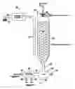
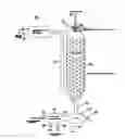
BRIEF DESCRIPTION OF THE DRAWINGThe drawing shows a “C” catalyst reactor in series with a “D” catalyst chamber which is also operating as a cooler scrubber.
DESCRIPTION OF PREFERRED EMBODIMENTReferring to the drawing, reference numeral 10 generally identifies a catalytic processing facility in which gaseous/vaporized feed stock containing organic compounds and oxygen containing compounds are fed via pipe 12 into catalytic cracking reactor 11 containing “C” catalyst (catalytic cracking catalyst such as a Houdry-type catalyst) where the organic molecules are cracked into molecules mostly in gasoline and fuel oil boiling fractions. The oxygen contained in the feed stock reacts with any carbon forming on the catalyst via the water gas reaction and/or the like, eliminating any carbon build-up. The hot gases and vapors leave 11 via pipe 13 and go into the “D” catalyst chamber 14 which also functions as a cooler-scrubber and which is filled with chunks of lime stone (calcium carbonate) 15 and is kept at around 340 degrees F. by a fluid such as brine, oil, and/or water, etc. spraying down on the limestone bed 15 from pipe 16 on the top of chamber 14. The limestone bed 15 is the “D” (acid decomposing) catalyst. The Hot gases and vapors from pipe 13 pass through the limestone bed 15 which converts any organic acids into aldehydes and ketones, and absorbs by reacting with any nitrogen oxides, sulphur oxides, halogens, halogen acids, etc. forming salts which are washed out by the cooling fluid together with the fuel oil fraction of organic compounds, condensed out of the gas-vapor stream, down pipe 18 into separator 17 where they are separated into fuel oil which goes out pipe 19 into storage tanks, the halogen salts, etc. which go out pipe 20, and the cooling fluid which goes out through pipe 21 into heat exchanger/waste heat boiler 22 which cools the cooling fluid back down to its normal working temperature, and generates steam in the process which goes to the sand-lime brick and building insulation manufacturing facilities via pipe 23 and returns via pipe 24. The cooled cooling fluid from boiler 22 goes out through pipe 25 and on through pipe 16 back into the top of the chamber 14 where it performs its duty again.
Meanwhile, the then cooled gas and gasoline (and lighter) vapors keep on rising up through limestone bed which is where the last drops of fuel oil are condensed out and washed downward by the cooling fluid. The then cooled gas and gasoline vapors exit chamber 14 via pipe 26 and go to a lower temperature condenser to condense out the gasoline fraction. Limestone is added to chamber 14 periodically through port 27.
Claims
1. The use of sludge from papermaking, waste water treatment, paper recycling, and other sources to make insulation via drying and/or other means.
2. The use of waste heat to manufacture insulation.
Images & Drawings included:
Sources:
- United States Patent and Trademark Office - verify current appl. status at the USPTO↗
Similar patent applications:
- » 20190291661
METHOD OF MANUFACTURING INSULATION FOR AUTOMOBILES AND INSULATION MANUFACTURED BY THE SAME - » 20220397228
HEAT INSULATING STRUCTURE, HEAT INSULATING BODY, METHOD FOR MANUFACTURING HEAT INSULATING STRUCTURE, AND METHOD FOR MANUFACTURING HEAT INSULATING BODY - » 20150314552
Heat insulating sheet, heat insulating material, method of manufacturing heat insulating sheet, and method of manufacturing heat insulating material - » 20240344758
VACUUM INSULATION PANEL, APPARATUS FOR MANUFACTURING VACUUM INSULATION PANEL, AND METHOD FOR MANUFACTURING VACUUM INSULATION PANEL - » 20110262749
THERMAL INSULATOR, THERMAL INSULATING COMPONENT, METHOD OF MANUFACTURING THERMAL INSULATING SMALL FIBER AND METHOD OF MANUFACTURING THERMAL INSULATOR - » 20130054061
Non-aqueous electrolyte battery, method of manufacturing non-aqueous electrolyte battery, insulating material, method of manufacturing insulating material, battery pack, electronic device, electromotive vehicle, power storage apparatus, and electric power system - » 20220154328
Insulating structure, method for manufacturing insulating structure, ion generation device, and ion implanter - » 20070196966
Method of manufacturing insulating film, method of manufacturing transistor, and method of manufacturing electronic device - » 20160250822
Radiant insulation protector manufacturing apparatus and radiant insulation protector manufactured using same - » 20060261718
Vacuum insulating material, refrigerator using vacuum insulating material, vacuum insulating material manufacturing method, and vacuum insulating material manufacturing equipment
Recent applications in this class:
- » 20220135892 2022-05-05
Sandwich gasification process for high-efficiency conversion of carbonaceous fuels to clean syngas with zero residual carbon discharge - » 20220049169 2022-02-17
Reactor and process for gasifying and/or melting of feed materials - » 20200208069 2020-07-02
Sandwich gasification process for high-efficiency conversion of carbonaceous fuels to clean syngas with zero residual carbon discharge - » 20200063051 2020-02-27
PROCESS FOR PRODUCING SYNTHESIS GAS BY GASIFYING SOLID CARBON CARRIERS - » 20180334624 2018-11-22
Plasma gasification reactor and method - » 20180327679 2018-11-15
Sandwich gasification process for high-efficiency conversion of carbonaceous fuels to clean syngas with zero residual carbon discharge - » 20150083971 2015-03-26
Method and apparatus for reduction of tar in gasification of carbonaceous materials - » 20140021028 2014-01-23
Biomass gasification/pyrolysis system and process - » 20120036777 2012-02-16
Sandwich gasification process for high-efficiency conversion of carbonaceous fuels to clean syngas with zero residual carbon discharge - » 20090260288 2009-10-22
Manufacture of gas from hydrogen-bearing starting materials