Device for thermally shrinking tools
US20050141978A1
2005-06-30
11/067,865
2005-02-28
✅ Patent granted
US 7,066,696 B2
2006-06-27
-
-
Erica Cadugan
2025-02-28
Abstract:
A heat shrink tool holder for holding tools and machine parts in an axial bore comprises a sleeve between the bore of the holder and the tool shank or machine part. The sleeve is a reducing sleeve that transfers a holding action exerted by the holder in its cold state to the tool shank or part. The sleeve is made of a material with a low thermal conductivity, like ceramic, and may be interchangeable or firmly fixed to the holder.
Assignee:
- REGO-FIX AG 11 🇨🇭 Tenniken, Switzerland
Interested in similar patents?
Get notified when new applications in this technology area are published.
Classification:
B23B31/117 » CPC further
Chucks ; Expansion mandrels; Adaptations thereof for remote control; Chucks characterised by the retaining or gripping devices or their immediate operating means Retention by friction only, e.g. using springs, resilient sleeves, tapers
B23P11/02 IPC
Connecting or disconnecting metal parts or objects by metal-working techniques not otherwise provided for by first expanding and then shrinking or e.g. by using pressure fluids; by making force fits
B23P11/027 » CPC main
Connecting or disconnecting metal parts or objects by metal-working techniques not otherwise provided for by first expanding and then shrinking or e.g. by using pressure fluids; by making force fits by using heat or cold for mounting tools in tool holders
B23B31/028 » CPC further
Chucks ; Expansion mandrels; Adaptations thereof for remote control; Chucks the axial positioning of the tool being adjustable
B23B31/1179 » CPC further
Chucks ; Expansion mandrels; Adaptations thereof for remote control; Chucks characterised by the retaining or gripping devices or their immediate operating means; Retention by friction only, e.g. using springs, resilient sleeves, tapers using heating and cooling
B23B31/201 » CPC further
Chucks ; Expansion mandrels; Adaptations thereof for remote control; Chucks characterised by the retaining or gripping devices or their immediate operating means; Chucks with simultaneously-acting jaws, whether or not also individually adjustable; Longitudinally-split sleeves, e.g. collet chucks Characterized by features relating primarily to remote control of the gripping means
B23B2226/18 » CPC further
Materials of tools or workpieces not comprising a metal Ceramic
B23B2260/026 » CPC further
Details of constructional elements Bushings, e.g. adapter sleeves
Y10T29/49865 » CPC further
Metal working; Method of mechanical manufacture; Assembling or joining with prestressing of part by temperature differential [e.g., shrink fit]
Y10T279/17957 » CPC further
Chucks or sockets; Socket type Friction grip
Y10T408/957 » CPC further
Cutting by use of rotating axially moving tool; Tool-support with tool-retaining means Tool adapter
Y10T409/30952 » CPC further
Gear cutting, milling, or planing; Milling with cutter holder
B23C5/00 IPC
Milling-cutters
Description
This application is a continuation of U.S. application Ser. No. 10/088,070, filed Mar. 8, 2002, now allowed, which is a National Stage Application under Section 371 of PCT Application Number PCT/CH00/00501, filed Sep. 18, 2000, the contents of which are incorporated by reference herein.
The invention relates to a device for thermally shrinking and expanding tools and other machine parts in a holder.
It is known in the metalworking and woodworking industry thermally to shrink tools in a holder. This is done by heating the holder and then inserting the tool shank. On cooling, the holder closes around the shank to create a firm, high-precision tool-holding device.
To enable the shank to be removed (tool expansion), the holder must be made of a material which has a larger thermal expansion than the shank. For a shank made of hard metal with a coefficient of thermal expansion of 6.10−6, an example of a suitable holder is one made of steel, which has twice the thermal expansion. A steel shank would in turn require a holder made of an aluminum alloy with a coefficient of thermal expansion twice that of steel.
If the holder and the shank to be shrunk are made of materials with the same or approximately the same thermal expansion, it is still possible to shrink the shank because only the holder is heated in the shrinking process, the shank being cold. Tool expansion is normally no longer possible because, when the holder is heated, the good thermal conductivity of metals is such that the shrunk shank heats up and expands together with said holder.
Even for shrinking, the shank has to be introduced quickly because the heat transfers very rapidly from the holder to the shank due to the good thermal conductance of metals.
The smaller the bore of the holder, the smaller is the thermal expansion on heating and the more exacting are the work tolerances. For example, if the thermal expansion is 0.048 mm for a bore diameter of 20 mm, then for the same material it is only 0.0072 mm for a bore diameter of 3 mm.
DE-19638808-A1 discloses a tool holder in which the tool shank is shrunk not in the clamping chuck but in a collet chuck. The latter is conventionally inserted in the conical housing of the clamping chuck by means of tensioning nuts. This device suffers from the same problems between collet chuck and tool shank as do the conventional shrink chucks in which a tool shank is shrunk directly.
The object of the invention is to avoid these disadvantages associated with thermal shrinking.
This is achieved according to the invention by means of a sleeve inserted in the bore of the holder, said sleeve preferably being made of a material with a low thermal conductivity.
A preferred embodiment of the invention will be described below with the aid of the attached drawing.
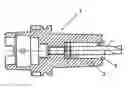
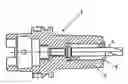
The drawing is a sectional diagram of a tool holder 1 with an inserted tool 2, which in this case is a twist drill. The width of the bore 3 of the holder is approximately twice the diameter of the drill shank. A sleeve 4 is located between the drill 2 and the holder. The sleeve is provided with slits cut in from one end, or alternately from both ends, to assure a degree of elasticity. However, the slits can also be omitted, depending on the material and the wall thickness.
As stated, the material of the sleeve 4 preferably has a low thermal conductivity so that the heat transfer from the heated holder to the tool is substantially delayed.
If the sleeve material does not have an especially low thermal conductivity, tool shrinking and expansion are facilitated by the greater thermal expansion due to the larger diameter of the holder, the only condition being that heating takes place rapidly, as in the case of inductive heating.
Apart from a low thermal conductivity, however, the material must also have a sufficiently high strength, toughness and hardness to cope with the stresses applied. Certain ceramic materials, e.g. zirconium oxide ceramic, offer this combination of properties.
The sleeve can be inserted in the tool holder in a variety of ways. It can either be inserted in the holder as an interchangeable reducing sleeve or fixed firmly to the holder, e.g. by press-fitting, adhesion, screwing, etc.
The advantages of interchangeable sleeves are as follows: With a holder of specific bore diameter, the insertion of interchangeable reducing sleeves makes it possible to clamp tools with different shank diameters.
When the holder is heated, the greater thermal expansion of the bore of the holder is transferred linearly through the reducing sleeve to its smaller bore. In this way, tool shanks made of a material with the same coefficient of thermal expansion as the holder can be shrunk and also expanded again.
Another advantage is that the small bore diameters of the reducing sleeve do not have to be manufactured with such extremely small work tolerances.
If overstressing causes the tool shank to rotate in the housing, at worst the reducing sleeve, and not the holder, will be damaged.
Claims
1. Heat shrink tool holder for being inserted in a machine spindle and for holding a tool shank or machine part, the heat shrink tool holder comprising a body having an axial bore, and a sleeve fitting in the axial bore of the body, the sleeve having a second bore to fit onto and contact the tool shank or part, the second bore being generally cylindrical, wherein the sleeve is a reducing sleeve that transfers a holding action exerted by the body in its cold state to the tool shank or part, wherein the body has the same coefficient of thermal expansion as the tool shank or part.
2. A heat shrink tool holder according to claim 1, wherein the body is made of the same material as the tool shank.
3. A heat shrink tool holder according to claim 1, wherein the body and the sleeve are made of the same material.
Images & Drawings included:
Sources:
- United States Patent and Trademark Office - verify current appl. status at the USPTO↗
Similar patent applications:
Recent applications in this class:
- » 20250073830 2025-03-06
AUTOMATED SHRINK-FITTING CELL - » 20240359275 2024-10-31
Shrink Fitting System - » 20240051072 2024-02-15
SHRINK-CLAMPING COOLING DEVICE, COOLING STATION AND METHOD - » 20230035681 2023-02-02
SHRINK-FIT CHUCK WITH NOVEL DAMPING, METHOD OF USING THE CHUCK AND TOOL-CLAMPING SYSTEM - » 20200316730 2020-10-08
Shrinking and / or shrinking clamping station for tools and method with a shrinking and / or shrinking clamping station for tools - » 20200061760 2020-02-27
INDUCTION COIL UNIT FOR A SHRINK DEVICE AND WITH CHUCK DETECTION AND AUTOMATIC COIL ADJUSTMENT - » 20190118314 2019-04-25
Device and method for inserting a tool into a tool receptacle - » 20190070698 2019-03-07
Adapter for a collet chuck, comprising a mounting - » 20190001446 2019-01-03
Shrink-fitting appliance for preferably mobile use - » 20150000121 2015-01-01
Apparatus for cooling a shrink-fit chuck
Recent applications for this Assignee:
- » 20190299351 2019-10-03
Clamping system - » 20130213194 2013-08-22
Slip-proof clamping system - » 20100327541 2010-12-30
Clamping system - » 20100071184 2010-03-25
Pressing device - » 20100061822 2010-03-11
Method and device for balancing a tool coupling - » 20090047079 2009-02-19
Coolant supply - » 20080072773 2008-03-27
Pressing device - » 20080054575 2008-03-06
Collet reduction with extracting device - » 10838677 2006-06-13
Pressing device - » 10089869 2006-11-28
Sealing device