Method and system for the automatic piloting of an aircraft on the approach to an airdrop position
US20050143904A1
2005-06-30
11/002,182
2004-12-03
✅ Patent granted
US 7,502,684 B2
2009-03-10
-
-
Ronnie Mancho
2026-10-02
Abstract:
Method and system for the automatic piloting of an aircraft on the approach to an airdrop position.
The system (1) comprises a means (2) for providing a speed profile that has to allow the aircraft to reach an airdrop position at a predetermined theoretical arrival time, with a predetermined speed, an automatic piloting device (3) for determining orders for piloting the aircraft so that it follows the speed profile, means of actuation (4) of controlled members (5) of the aircraft, to which the piloting orders are applied, a means (6) for determining an actual arrival time at which the aircraft will actually reach the airdrop position, and a means (8) for correcting the speed profile, as a function of the actual arrival time and of the theoretical arrival time, the speed profile thus corrected being provided to the automatic piloting device (3).
Assignee:
- AIRBUS FRANCE 623 🇫🇷 Toulouse, France
Interested in similar patents?
Get notified when new applications in this technology area are published.
Classification:
G06F17/00 IPC
Digital computing or data processing equipment or methods, specially adapted for specific functions
G01C21/30 IPC
Navigation; Navigational instruments not provided for in groups - specially adapted for navigation in a road network with correlation of data from several navigational instruments Map- or contour-matching
G05D1/105 » CPC main
Control of position, course or altitude of land, water, air, or space vehicles, e.g. automatic pilot; Simultaneous control of position or course in three dimensions specially adapted for aircraft specially adapted for unpowered flight, e.g. glider, parachuting, forced landing
Description
The present invention relates to a method and system for the automatic piloting of an aircraft on the approach to an airdrop position.
In order to carry out an airdrop, for example of hardware and/or troops, it is generally necessary for the aircraft, for example a military transport plane, to arrive at the airdrop position planned during mission preparation at a predetermined arrival time, so as to be able to make the airdrop at the scheduled time, in particular when troops are on the ground to receive the airdropped elements. Moreover, to facilitate the airdrop, it is preferable for the aircraft to arrive at said airdrop position with a constant predetermined speed.
Also, to be able to fulfill these conditions, a particular speed profile with decreasing speed is generally determined and is applied to the aircraft during the approach phase, between the cruising speed and said predetermined airdrop speed. Moreover, to facilitate the work of the releaser and to avoid too much jerkiness, such a speed profile generally comprises a plurality of constant-speed levels separated by deceleration phases.
Of course, this speed profile is determined during mission preparation. It takes no account of the wind.
Under these conditions, the predetermined speed profile is not optimal and does not make it possible to reach the airdrop position at the scheduled arrival time so that the airdrop is then made either early or late relative to the scheduled time.
An object of the present invention is to remedy these drawbacks. It relates to a method of automatic piloting of an aircraft during a phase of approach to a predetermined airdrop position, at which an airdrop is to be made from said aircraft, making it possible to devise and apply to said aircraft an optimal speed profile which allows the latter to reach said airdrop position exactly at the initially scheduled time.
For this purpose, said method, according to which:
-
- in the course of said approach phase, a speed profile with decreasing speed comprising a plurality of constant-speed levels, separated by deceleration phases, is applied automatically to the aircraft; and
- the aircraft must reach said airdrop position at a predetermined theoretical arrival time, with a predetermined speed,
is noteworthy, according to the invention, in that, in the course of said approach phase, automatically: - an actual arrival time at which the aircraft will actually reach said airdrop position is determined;
- the difference between said theoretical and actual arrival times is calculated; and
- if this difference differs from zero;
- said speed profile is corrected by modifying the length of at least two constant-speed levels in such a way as to cancel said difference; and
- said speed profile thus corrected is applied to said aircraft.
Thus, by virtue of the invention, the speed profile is corrected, if necessary, in such a way as to have (and to apply to the aircraft) permanently an optimal speed profile making it possible to reach said airdrop position at said predetermined theoretical arrival time.
This correction may be made throughout the approach phase. Moreover, it is implemented automatically, thereby allowing the crew to be unburdened of this task and to concentrate on other tasks or actions that are necessary, in particular with a view to the airdrop. Furthermore, said correction is made in a simple and fast manner, but without modifying the overall aspect of the speed profile.
When said actual arrival time is later than said theoretical arrival time, that is to say when the aircraft is late, advantageously, the length of at least one first level exhibiting a first constant speed is increased, and the length of at least one second level exhibiting a second constant speed is decreased, said first speed being greater than said second speed.
In this case, advantageously, said first level is increased and said second level is decreased by one and the same length xa which satisfies the following relation:
xa
=
Δ
t
·
Vi
·
Vj
(
Vj
-
Vi
)
in which:
-
- Δt represents said time difference (between said theoretical and actual arrival times);
- Vi represents said first constant speed; and
- Vj represents said second constant speed.
Furthermore, when said actual arrival time is earlier than said theoretical arrival time, that is to say when the aircraft is early, advantageously, the length of at least one first level exhibiting a first constant speed is decreased, and the length of at least one second level exhibiting a second constant speed is increased, said first speed being greater than said second speed.
In this case, advantageously, said first level is decreased and said second level is increased by one and the same length xb which satisfies the following relation:
xb
=
Δ
t
·
Vi
·
Vj
(
Vi
-
Vj
)
in which:
-
- Δt represents said time difference (between said theoretical and actual arrival times);
- Vi represents said first constant speed; and
- Vj represents said second constant speed.
In a particular embodiment:
-
- the length of more than two constant-speed levels is modified; and/or
- the length of at least one constant-speed level is decreased completely in such a way as to eliminate this level.
The present invention also relates to a system for the automatic piloting of an aircraft so as to pilot said aircraft at least during a phase of approach to a predetermined airdrop position, at which an airdrop is to be made from said aircraft.
According to the invention, said system of the type comprising:
-
- a first means for providing a speed profile that has to allow the aircraft to reach said airdrop position at a predetermined theoretical arrival time, with a predetermined speed;
- an automatic piloting device for determining orders for piloting the aircraft so that it follows said speed profile; and
- means of actuation of controlled members of the aircraft, to which said piloting orders are applied,
is noteworthy in that it moreover comprises: - a second means for determining an actual arrival time at which the aircraft will actually reach said airdrop position; and
- a third means for correcting said speed profile, as a function of said actual arrival time and of said theoretical arrival time, the speed profile thus corrected being provided to said automatic piloting device to determine corresponding piloting orders which are applied to said means of actuation.
In a particular embodiment, said first means comprises a diskette, on which is recorded said speed profile, and which-can be read, with the aid of a suitable means of reading, by said automatic piloting device, this making it possible to devise the speed profile during mission preparation and to record it on said diskette. It is then sufficient to simply enter said diskette into said reading means in order for the automatic piloting device to take account of said recorded speed profile, thus making it possible to considerably decrease the workload of the crew.
Furthermore, advantageously, said third means is integrated into said automatic piloting device.
The figures of the appended drawing will elucidate the manner in which the invention may be embodied. In these figures, identical references designate similar elements.
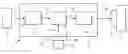
FIG. 1 is the schematic diagram of a piloting system in accordance with the invention.
FIGS. 2 to 6 are graphs showing various speed profiles, allowing proper comprehension of the present invention.
The system 1 in accordance with the invention and represented diagrammatically in FIG. 1 is intended for the automatic piloting of an aircraft (not represented), for example a military transport plane, so as to pilot said aircraft at least during a phase of approach to a predetermined airdrop position, at which an airdrop of hardware and/or of troops is to be made from said aircraft.
Said system 1 comprises:
-
- a means 2 for providing a speed profile PV that allows the aircraft to reach said airdrop position at a predetermined theoretical arrival time TO, with a predetermined speed;
- an automatic piloting device 3, for example an automatic pilot, for determining orders for piloting the aircraft so that it follows said speed profile PV; and
- means of actuation 4 of controlled members 5 such as for example control surfaces (rudder, elevators, etc.) of the aircraft, which means of actuation 4 are connected to said device 3 and to which the piloting orders determined by the latter are applied.
To be able to automatically update said speed profile PV, essentially when the aircraft is in said approach phase, said system 1 moreover comprises:
-
- a means 6 which is connected by a link 7 to the device 3, for determining an actual arrival time Teff, at which the aircraft will actually reach said airdrop position, on the basis of information currently available (the current position of the aircraft and current conditions such as the characteristics of the wind, etc.); and
- a means 8 which is integrated into the device 3, for correcting said speed profile PV, as a function of said actual arrival time Teff and of said theoretical arrival time TO, the speed profile thus corrected being used to calculate new piloting orders which are applied to said means of actuation 4.
According to the invention, the speed profile PV, whose speed V is applied to the aircraft between an earlier cruising phase at constant speed VC and the airdrop position 9 reached at a speed V1 comprises, as represented in FIG. 2:
-
- levels P1, P2, P3 at constant speed, respectively at speeds V1, V2 and V3; and
- deceleration phases E1, E2, E3, which each time connect two successive levels P1, P2, P3. Preferably, said deceleration phases E1, E2, E3 exhibit the same deceleration factor a.
Since the speeds V1, V2 and V3 are constant values, as is said deceleration factor a, the same holds for the distances d1 and d2 for switching respectively from the speeds V2 to V1 and V3 to V2 or the corresponding times t1 and t2 necessary for this deceleration. Specifically, these parameters satisfy the following relations: { t1 = ( V1 - V2 ) / a t2 = ( V2 - V3 ) / a d1 = ( V1 - V2 ) · ( V1 + V2 ) / ( 2 a ) d2 = ( V2 - V3 ) · ( V2 + V3 ) / ( 2 a )
The same holds for any parameter tn or dn between a speed Vn+1 of a level Pn+1 and a speed Vn of a level Pn according to: { tn = ( Vn - Vn + 1 ) / a dn = ( Vn - Vn + 1 ) · ( Vn + Vn + 1 ) / ( 2 a )
According to the invention, said device 3 comprises:
-
- a means 10 which is connected by a link 11 to the means 6, for calculating the difference At between said theoretical and actual arrival times TO and
Teff: Δt=Teff−TO; - said means 8 which is connected by a link 12 to the means 10, which compares this difference Δt with zero and which, if this difference Δt differs from zero, corrects said speed profile PVreceived from the means 2 via a link 13, by modifying the length of at least two constant-speed levels in such a way as to cancel said difference Δt; and
- a means 14 which is connected by a link 15 to the means 8, which receives the speed profile (corrected or otherwise) from said means 8 and which calculates piloting orders in accordance with this speed profile, which it transmits to said means of actuation 4 by way of a link 16.
- a means 10 which is connected by a link 11 to the means 6, for calculating the difference At between said theoretical and actual arrival times TO and
In a particular embodiment, said means 2 comprises a diskette 17, on which is recorded said speed profile PV, and which can be read, with the aid of a means of reading 18, by said automatic piloting device 3.
This makes it possible to devise the speed profile PV during mission preparation and to record it on said diskette 17. It is then sufficient to simply enter said diskette 17 into said reading means 18 in order for the automatic piloting device 13 to take account of said recorded speed profile PV, thus making it possible to considerably decrease the workload of the crew.
More precisely, according to the invention, when said actual arrival time Teff is later than said theoretical arrival time TO, that is to say when the aircraft is late with respect to the scheduled time, in order to make up for this lateness, the length of at least one first level, for example the level P3, exhibiting a first constant speed (for example V3) is increased, and the length of at least one second level, for example the level P2, exhibiting a second constant speed (for example V2) which is less than said first constant speed (for example V3) is decreased.
In this case, when the length of only said two levels P3 and P2 is modified, said level P3 is increased and said level P2 is decreased by one and the same length x1 which satisfies the following relation: X1 = Δ t · V2 · V3 ( V2 - V3 )
The level P3 then exhibits a length L3a=L3+x1 and the level P2 a length L2a=L2−x1, as represented in FIG. 3 which shows the speed profile PVa obtained by this correction.
Such a modification of the length of level is possible up to a maximum value of x1 which satisfies:
x1=D2−D1−d1,
this corresponding to a maximum lateness that can be made up for of
Δt=(D2−D1−d1).(V3−V2)/(V3.V2).
It will be noted that D1, D2 and D3 represent the distances between the airdrop position 9 and the starts respectively of said levels P1, P2 and P3, as represented in FIG. 2.
It will be furthermore noted that the time required to reach the airdrop position 9, from the start of the level P3, is:
ti=(D3−D2−d2)/V3+t2+(D2−D1−d1)/V2+t2+D1/V1,
with the uncorrected initial speed profile PV of FIG. 2; and
tj=(D3+x1−D2−d2)/V3+t2+(D2−D1−x1−d1)/V2+t1+D1/V1,
with the corrected speed profile PVa of FIG. 3.
Additionally, according to the invention, when said actual arrival time Teff is earlier than said theoretical arrival time TO, that is to say when the aircraft is early with respect to the scheduled time, in order to cancel this earliness, the length of at least one first level, for example the level P3, exhibiting a first constant speed (for example V3) is decreased, and the length of at least one second level, for example the level P2, exhibiting a second constant speed (for example V2) which is less than said first constant speed (for example V3) is increased.
In this case, when the length of only the two levels P3 and P2 is modified, said level P3 is increased and said level P2 is decreased by one and the same length x2 which satisfies the following relation: X2 = Δ t · V2 · V3 ( V2 - V3 )
The level P3 then exhibits a length L3b=L3−x2 and the level P2 a length L2b=L2+x2, as represented in FIG. 4 which shows the speed profile PVb obtained by this correction.
Such a modification is possible up to a maximum value of x2 which satisfies:
x2=D3−D2−d2,
this corresponding to a maximum earliness that can be delayed of
Δt=(D3−D2−d2).(V3−V2)/(V3.V2).
It will be noted that the time tk required to reach the airdrop position 9, from the start of the level P3, then satisfies the relation:
tk=(D3−D2−d2−x1)/V3+t2+(D2−D1−d1+x1)/V2+t1+D1/V1,
with the corrected speed profile Pvb of FIG. 4.
More generally, when the speed profile PV comprises n levels P1, P2, . . . , Pn-2, Pn-1, Pn, respectively of constant speeds V1 to Vn, as represented partially in FIG. 5, it is possible to apply the modification of length of levels in accordance with the invention, to any two (or more than any two) of said n levels P1 to Pn.
Thus, by applying it between a level Pn and a level Pn-1, it is possible:
-
- either to make up for a duration t1 such that:
t1=(Dn-1−Dn-2−dn-2) (Vn−Vn-1)/(Vn.Vn-1); - or to slow down the flight by a duration tm such that:
tm=(Dn−Dn-1−dn-1) (Vn−Vn-1)/(Vn.Vn-1).
- either to make up for a duration t1 such that:
If such a duration t1 or tm is insufficient, it is possible to carry out the same operation between two other levels, for example the levels Pn-1 and Pn-2 of the speed profile, and so and so forth if necessary.
In a particular embodiment, it is possible to decrease the length of a level Pn-1 until it is completely eliminated, as represented in FIG. 6.
In this case, the corrected speed profile PVc exhibits a level Pn of length Lnc=Ln+Ln-1 and the deceleration phase Ec between the levels Pn and Pn-2 exhibits the length (and hence the duration) of the two initial deceleration phases En-1 and En-2 represented in FIG. 5. The correction illustrated in FIG. 6, for which the length Ln-1 of the eliminated level Pn-1 is transmitted to a level Pn at greater constant speed Vn enables a lateness to be made up for.
On the other hand, if it is necessary to delay earliness, this length Ln-1 of the eliminated level Pn-1 is transmitted to a level Pn-2 at lower constant speed Vn-2.
Consequently, the system 1 in accordance with the invention corrects, if necessary, the speed profile PV in such a way as to have (and to apply to the aircraft) permanently an optimal speed profile making it possible to reach said airdrop position 9 at said predetermined theoretical arrival time TO.
This correction may be made throughout the approach phase. Moreover, it is implemented automatically by said system 1, thereby allowing the crew to be unburdened of this task and to concentrate on other tasks or actions that are necessary, in particular with a view to the airdrop.
Furthermore, the correction implemented by the system 1 is made in a simple and fast manner, but without modifying the overall aspect of the speed profile PV.
Claims
1. A method of automatic piloting of an aircraft during a phase of approach to a predetermined airdrop position ( 9), at which an airdrop is to be made from said aircraft, method according to which:
in the course of said approach phase, a speed profile (PV) with decreasing speed comprising a plurality of constant-speed levels (P1 to Pn), separated by deceleration phases (E1 to En), is applied automatically to the aircraft; and
the aircraft must reach said airdrop position (9) at a predetermined theoretical arrival time, with a predetermined speed,
wherein, in the course of said approach phase, automatically:
an actual arrival time at which the aircraft will actually reach said airdrop position (9) is determined;
the difference between said theoretical and actual arrival times is calculated; and
if this difference differs from zero;
said speed profile (PV) is corrected by modifying the length of at least two constant-speed levels in such a way as to cancel said difference; and
said speed profile (PVa, PVb, PVc) thus corrected is applied to said aircraft.
2. The method as claimed in claim 1,
wherein, when said actual arrival time is later than said theoretical arrival time, the length (L3) of at least one first level (P3) exhibiting a first constant speed (V3) is increased, and the length (L2) of at least one second level (P2) exhibiting a second constant speed (V2) is decreased, said first speed (V3) being greater than said second speed (V2).
3. The method as claimed in claim 2,
wherein said first level (P3) is increased and said second level (P2) is decreased by one and the same length xa which satisfies the following relation:
xa = Δ t · Vi · Vj ( Vj - Vi )
in which:
Δt represents said time difference;
Vi represents said first constant speed; and
Vj represents said second constant speed.
4. The method as claimed in claim 1,
wherein, when said actual arrival time is earlier than said theoretical arrival time, the length (L3) of at least one first level (P3) exhibiting a first constant speed (V3) is decreased, and the length (L2) of at least one second level (P2) exhibiting a second constant speed (V2) is increased, said first speed (V3) being greater than said second speed (V2).
5. The method as claimed in claim 4,
wherein said first level (P 3) is decreased and said second level (P 2) is increased by one and the same length xb which satisfies the following relation:
xb = Δ t · Vi · Vj ( Vi - Vj )
in which:
Δt represents said time difference;
Vi represents said first constant speed; and
Vj represents said second constant speed.
6. The method as claimed in claim 1,
wherein the length of more than two constant-speed levels is modified.
7. The method as claimed in claim 1,
wherein the length (Ln-1) of at least one constant-speed (Vn-1) level (Pn-1) is decreased completely in such a way as to eliminate this level (Pn-1).
8. A system for the automatic piloting of an aircraft so as to pilot said aircraft at least during a phase of approach to a predetermined airdrop position (9), at which an airdrop is to be made from said aircraft, said system (1) comprising:
a first means ( 2) for providing a speed profile (PV) that has to allow the aircraft to reach said airdrop position ( 9) at a predetermined theoretical arrival time, with a predetermined speed;
an automatic piloting device (3) for determining orders for piloting the aircraft so that it follows said speed profile (PV); and
means of actuation (4) of controlled members (5) of the aircraft, to which said piloting orders are applied,
which system moreover comprises:
a second means (6) for determining an actual arrival time at which the aircraft will actually reach said airdrop position (9); and
a third means (8) for correcting said speed profile (PV), as a function of said actual arrival time and of said theoretical arrival time, the speed profile (PVa, PVb, PVc) thus corrected being provided to said automatic piloting device (3) to determine corresponding piloting orders which are applied to said means of actuation (4).
9. The system as claimed in claim 8,
wherein said first means (2) comprises a diskette (17), on which is recorded said speed profile (PV), and which can be read, with the aid of a means of reading (18), by said automatic piloting device (3).
10. The system as claimed in claim 8,
wherein said third means (8) is integrated into said automatic piloting device (3).
11. An aircraft,
which comprises a system (1) such as that specified under claim 8.
12. An aircraft,
which comprises a system (1) able to implement the method specified under claim 1.
Images & Drawings included:


Sources:
- United States Patent and Trademark Office - verify current appl. status at the USPTO↗
Recent applications in this class:
- » 20240329643 2024-10-03
PRECISION ARIAL DROP SYSTEM - » 20210109549 2021-04-15
UNMANNED AIRCRAFT SYSTEM CAPABLE OF AUTONOMOUS FLIGHT - » 20200285253 2020-09-10
Unmanned aircraft and method for controlling unmanned aircraft - » 20190129449 2019-05-02
Atmospheric thermal location estimation - » 20180129226 2018-05-10
HELICOPTER AUTOROTATION CONTROLLER - » 20170308104 2017-10-26
Airborne vehicle recovery - » 20170017241 2017-01-19
Pilot assistance system - » 20160378121 2016-12-29
Landing aircrafts with optimal landing spot selection - » 20150153741 2015-06-04
Tethered vehicle control and tracking system - » 20150153740 2015-06-04
Safe emergency landing of a UAV
Recent applications for this Assignee:
- » 20120328385 2012-12-27
Machining means for ceiling fixed parts - » 20120325958 2012-12-27
Aircraft with rear annular tail - » 20120284006 2012-11-08
Method of determining the particle sensitivity of electronic components - » 20110226899 2011-09-22
Autonomous plane architecture for the transport and the replacement of propulsion engines - » 20110198918 2011-08-18
Device and method for emergency electricity supply on board an aircraft - » 20110004361 2011-01-06
Method and device for estimating the forces exerted on a control surface of an aircraft - » 20100332111 2010-12-30
Device for guiding an aircraft along a flight trajectory - » 20100319801 2010-12-23
System for weaving a continuous angle - » 20100301161 2010-12-02
Acoustic coating for an aircraft incorporating a frost treatment system by joule effect - » 20100297390 2010-11-25
Self-stabilised stiffener enabling element recovery