Method for designing development drawing of developable surface
US20050143964A1
2005-06-30
10/867,783
2004-06-16
✅ Patent granted
US 7,548,838 B2
2009-06-16
-
-
Hugh Jones
2025-08-19
Abstract:
Disclosed is a method for designing a development drawing of a developable surface, the method including the steps of: setting a control contour from a circumference surface of a 3-dimensional model; performing an algorithm LIDM-GC-Dvlp to search a control point set; outputting a control point of a profile curve; visualizing a developable surface typed general circumference surface; modifying a design by a user depending on the visualized result; selecting a developable surface segment intended to generate the development drawing; and performing an algorithm LIDM-GC-Plane-Dvlp for the control point to generate the development drawing.
Inventors:
- Joo Haeng Lee 3 🇰🇷 Taejon, South Korea
- Hyun Kim 3 🇰🇷 Taejon, South Korea
- Hyoung Sun Kim 2 🇰🇷 Taejon, South Korea
- Jin Mi Jung 2 🇰🇷 Okcheon, South Korea
- Jin Mi Jung 2 🇰🇷 Choongchungbuk-Do, South Korea
Assignee:
- Electronics and Telecommunications Research Institute 117 🇰🇷 Taejon, South Korea
Interested in similar patents?
Get notified when new applications in this technology area are published.
Classification:
G06T17/30 » CPC main
Three dimensional [3D] modelling, e.g. data description of 3D objects Polynomial surface description
G06F17/10 IPC
Digital computing or data processing equipment or methods, specially adapted for specific functions Complex mathematical operations
Description
BACKGROUND OF THE INVENITON1. Field of the Invention
The present invention relates to a method for designing a developable surface and a development drawing applied to a computer, and more particularly, to a method in which a developable surface is designed to be a general circumferential surface using a direction map, and a property of the direction map is used to generate a corresponding development drawing on a plane.
2. Description of the Related Art
A way for drawing a development drawing of an object that can be approximate to a plane such as a thin iron plate (sheet metal), a paper and the like, cutting the object for assembly, and then making a curved-surface shaped cubic figure is generally mainly used in shipbuilding and car industries and the like. A curved-surface that can make the development drawing in the above way is called a developable surface in mathematics. Since a complex mathematical calculation is required to design the developable surface and generate the development drawing thereof, a CAD (Computer Aided Design) system using a computer is used.
In a design of the curved-surface shaped cubic figure, a direction map based general circumference surface is a curved-surface modeling method that is essential for geometric modeling since a contour shape can be controlled to facilitate a control of an entire curved-surface shape and further a simple calculation can be performed. However, a method for designing the general circumference surface to be the developable surface is not known.
SUMMARY OF THE INVENTIONAccordingly, the present invention is directed to a method for designing a development drawing of a developable surface and, which substantially obviates one or more problems due to limitations and disadvantages of the related art.
It is an object of the present invention to provide a method for designing a development drawing of a developable surface in which a conventional method is improved in designing a direction map based general circumference surface such that an entire surface can be effectively generated using a definition of a sequential factoring curve without generating a finite number of middle contours, in which a special condition is provided for allowing the general circumference surface designed by the above method to be the developable surface by a property of the direction map, and in which a development drawing of the direction map based general circumference surface for satisfying the above condition is generated in a 2-dimension.
Additional advantages, objects, and features of the invention will be set forth in part in the description which follows and in part will become apparent to those having ordinary skill in the art upon examination of the following or may be learned from practice of the invention. The objectives and other advantages of the invention may be realized and attained by the structure particularly pointed out in the written description and claims hereof as well as the appended drawings.
To achieve these objects and other advantages and in accordance with the purpose of the invention, as embodied and broadly described herein, there is provided a method for designing a development drawing of a developable surface, the method including the steps of: setting a control contour from a circumference surface of a 3-dimensional model; performing an algorithm LIDM-GC-Dvlp to search a control point set; outputting a control point of a profile curve; visualizing a developable surface typed general circumference surface; modifying a design by a user depending on the visualized result; selecting a developable surface segment intended to generate the development drawing; and performing an algorithm LIDM-GC-Plane-Dvlp for the control point to generate the development drawing.
It is to be understood that both the foregoing general description and the following detailed description of the present invention are exemplary and explanatory and are intended to provide further explanation of the invention as claimed.
BRIEF DESCRIPTION OF THE DRAWINGSThe accompanying drawings, which are included to provide a further understanding of the invention, are incorporated in and constitute a part of this application, illustrate embodiments of the invention and together with the description serve to explain the principle of the invention. In the drawings:
FIG. 1 is a view illustrating a general computer system for embodying the present invention;
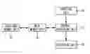
FIG. 2 is a flow chart illustrating a method for designing a development drawing of a developable surface according to the present invention;
FIG. 3 is an algorithm for calculating a control point of a boundary of a developable surface according to the present invention;
FIG. 4 is an embodiment using algorithm of FIG. 3;
FIG. 5 is a view illustrating a principle of developing a developable surface on a plane;
FIG. 6 is an algorithm for developing a developable surface on a plane; and
FIG. 7 is an exemplary view illustrating a 3-dimensional model that is assembled using a development drawing designed through algorithms of FIGS. 3 and 6.
DETAILED DESCRIPTION OF THE INVENTIONReference will now be made in detail to the preferred embodiments of the present invention, examples of which are illustrated in the accompanying drawings.
FIG. 1 is a view illustrating a general computer system for embodying a method for designing a development drawing of a developable surface according to the present invention.
Referring to the drawing, the computer system includes: a central processing unit 10 for controlling an entire computer system; a main memory unit 20 for storing all data necessary for development execution therein; an auxiliary memory unit 30 for temporarily storing therein and outputting work data therefrom depending on a control of the central processing unit 10; an inputting unit 40 for commanding a motion to the central processing unit 10 depending on worker's manipulation; and an outputting unit 50 for displaying a work state.
The design method of the development drawing that the present invention intends to disclose is programmed to be stored in a recording media in a computer-readable format. The program stored in the recording media is managed on the computer such that the development drawing of a developable 3-dimensional virtual surface inputted through the inputting unit 40 can be outputted on a 2-dimensional plane, and an initially inputted developable surface can reappear in a 3-dimensional model by combining the outputted development drawing.
FIG. 2 is a flow chart illustrating the method for designing the development drawing of the developable surface according to the present invention.
Referring to the drawing, the design method for designing the development drawing of the developable surface according to the present invention including the steps of: setting a control contour from a 3-dimensional model (S201); performing an algorithm LIDM-GC-Dvlp (S202); outputting a control point of a profile curve (203); visualizing a developable surface typed general circumference surface (S204); modifying a design by a user depending on the visualized result (S205); selecting a developable surface segment intended to generate the development drawing (S206); performing an algorithm LIDM-GC-Plane-Dvlp for the control point to generate the development drawing (S207); and printing or engraving the generated development drawing on a plane material (S208).
Accordingly, the present invention performs a routine of the above steps such that the development drawing of a developable 2-dimensional or 3-dimensional surface is designed on a 2-dimensional plane, and performs steps of 209 and 210 to cut the designed development drawing and to adjoin adjacent development drawings such that the 3-dimensional model is assembled.
Hereinafter, in order to be helpful for understanding in programming to enable the design method of the development drawing of the developable surface to be executed in the computer, simple mathematical definitions are arranged.
In the present invention, a general circumference is comprised of at least two 2-dimensional contours and a curve on 2-dimension or 3-dimension at which the contours are disposed. At this time, this curve is called a spine curve of the general circumference.
The general circumference can be specifically exemplified as a right cylinder. In the right cylinder, the contour is a combination circle constituting a bottom surface and a top surface of the cylinder, and the spine curve is a line segment right-angled to a contour circle.
The spine curve and the boundary of the contour are expressed as a 2-dimensional or more curve, or a point set being representative of the curve. In case that they are expressed using the point set, the contour boundary can be viewed as a polygon, and the spine curve can be viewed as a polyline.
In the present invention, the contour defining the general circumference is the polygon. It is assumed that the polygon is expressed by at least three vertices, and the boundary connecting them is always clockwise.
A direction map of the polygon is a circular arrangement of vectors defined using two adjacent vertices. At t this time, these vectors are called direction vectors. For example, two adjacent vertices (Pi, Pi+1) define one direction vector di=Pi+1−pi.
If two direction maps are merged, a new direction map can be obtained. If the direction vector of the new direction map is orderly connected, a new figure can be obtained. The new figure is different depending on how the direction map is merged. A merge of the direction map is to rearrange an order of the direction vectors according to an appropriate rule. The merge of the direction vector is exemplified as a convolution merge or a merge of a minimum convex hull.
The below described present invention is not limited to a specific merge method. It is called a group unit based size control operation that the direction vector of the merged direction map is divided into a group to adjust its length.
A new middle figure can be made for interpolating given polygons through the merge and the group unit based size control operation. A conventional patent using the above fact has ever provided a method for generating a finite number of middle figures as the contour and generating a polygon mesh connecting the contours to perform an approximation of the general circumference surface.
This method has a simple calculation way, but has a disadvantage in which a middle contour should be generated. That is, if a precision degree of the general circumference surface becomes different, the middle contour should be again calculated. Further, since the surface generated in a type of a polygon mesh is stored, it can be regarded to have a large amount of data.
A ruled surface is defined by a straight line moving along the curve. At this time, the curve is called a directrix and the straight line is called a ruling.
The developable surface is a particular type of the ruled surface. Specifically, there is a property that all points existing at a specific ruling of the developable surface has the same tangent plane.
Due to this, the developable surface can be spread on the plane without stretching or tearing. This property is usefully used in a manufacture way using material of a sheet metal type. For example, it is very appropriate in designing streamlined traffic means and the like for minimizing fluid resistance.
When the contours of the general circumference surface all have the same orientation, all corresponding line segments of the mixed contours are parallel to one another. This is because corresponding line segments are defined using the same direction vector. Accordingly, each direction vector moving along a specific directrix is defined as di, and a circumference typed developable surface segment is defined as Si.
The present invention provides the design method of the development drawing of the circumference typed developable surface. A conic typed developable surface is not described since it is merely a basic technique of the present invention.
In order to enable the inventive design method, the contours defining the general circumference surface should be all put on a parallel plane as in the step 201. This is a condition for fixing the direction vector along the spine curve to design the conic typed developable surface.
Each developable surface segment Si is defined as two boundary curves. These are respectively defined as Fi−1(u) and Fi(u), and are called profile curves (Referring to FIG. 5A).
Each of the profile curves corresponds to the path on which one vertex of one contour moves. By the property of the merge direction map and the group unit based size control operation, each of the vertices of the mixed contours is defined as a mixture of the vertices of a control contour. At this time, the mixture ratio follows a size control factor specified in the group unit based size control operation.
If Bernstein polynomial Bjm(u) is used as the size control factor, the profile curve Fi(u) is expressed as Bezier curve such as the following Equation 1. F i ( u ) = ∑ j = 0 m B j m ( u ) · p i , j . [ Equation 1 ]
If the size control factor is used as another basis function, a property of the profile curve is also differentiated. For example, it can be NURBS or blossom curve typed.
An adjacent profile curve satisfies the property such as the following Equation 2.
(Fi(u)−Fi−1(u),di)=0.
(pi,j−pi-j,di)=0. [Equation 2]
Accordingly, corresponding control points Pi−1,j and Pi,j of the profile curves Fi−1(u) and Fi(u) of the developable surface segment Si defined by the direction vector di have one relation of the followings.
(1) the corresponding control point is consistent (Pi−1,j=Pi,j), or otherwise.
(2) the corresponding control point is put on the plane parallel with the corresponding direction vector di (Pi−1,j−Pi,j)//di.
Based on this rule, the algorithm of FIG. 3 is operated for enabling the step 202. This algorithm is called “LIDM-GC-Dvlp”. The algorithm disclosed in FIG. 3 searches a control point set for defining the developable surface.
The control point searched using the algorithm LIDM-GC-Dvlp disclosed in FIG. 3 can be used to express the developable surface segment Si using a factoring equation such as the following Equation 3. In the below example, a Bernstein polynomial is used as the size control factor. S i ( u , v ) = ( 1 - v ) F i - 1 ( u ) + vF i ( u ) = ( 1 - v ) ∑ j = 0 m B j m ( u ) · p i - 1 , j + v ∑ j = 0 m B j m ( u ) · p i , j = ∑ j = 0 m ∑ k = 0 1 B j m ( u ) B k 1 ( u ) · p i - 1 + k , j [ Equation 3 ]
According to the Equation 3, it can be understood that the generated developable surface segment is a (m,1) order of Bezier surface.
FIG. 4 in detail illustrates the steps 202 to 204 of FIG. 2.
Referring to the drawing, the present invention shows a procedure of searching the control point of the developable surface segment using the algorithm LIDM-GC-Dvlp, and inserting the searched control point into the factoring equation to represent an entire developable surface.
FIG. 4A illustrates four control contours provided for defining the general circumference. Made is the surface connecting small rectangles having different orientations from one another at both ends. At this time, a large rectangular control contour disposed at a middle portion additionally controls a shape of the surface.
FIG. 4B illustrates a middle contour generated using the control contours of FIG. 4A so as to generate the polygonal mesh in a conventional method of generating the direction map based general circumference.
FIG. 4C illustrates the mesh for connecting the middle contour according to the conventional method of generating the direction map based general circumference. Particularly, the bottom surface (sky blue) portion corresponds to a locus on which any one direction vector moves while the length is changed.
FIG. 4D shows a result of searching the control point defining the surface segment of FIG. 4C among the vertices of the control contour, by using the algorithm LIDM-GC-Dvlp.
FIG. 4E shows the profile curves defined by the entire control point searched by using the method as in FIG. 4D.
FIG. 4F illustrates the searched control point expressed in the factoring surface type as in the Equation.
The development drawing of the above-generated developable surface can be easily drawn on the plane. The step 206 is described in the following.
The present invention defines a particular directrix Fid(t) for each developable surface segment Si. This directrix is called a normal directrix. The normal directrix Fid(t) is put on the plane vertical to the di defining the developable surface segment Si. (Referring to FIGS. 5A and 5B).
The control point di,jd of the normal directrix can be searched from the following Equation 4. d i = p i , k - p i - 1 , k , ( d i ≠ 0 ) p i - 1 , 0 = p i d , 0 , p i - 1 , j = p i , j d + h i , j L · d i p i , j = p i , j d + h i , j U · d i = p i + 1 , j d + h i + 1 , j L · d i + 1 . [ Equation 4 ]
In the above Equation, the hi,jL and the hi,jU are scalar values. A relation of the Equation 4 is expressed in FIG. 5A and FIG. 5B.
There is the property that the control points di,jd of the normal directrix are put on the same plane. This is expressed in the following Equation 5. 0 = 〈 ( p i - 1 , j d - p i - 1 , 0 d ) , d i 〉 = 〈 ( p i - 1 , j - h i , j L · d i - p i - 1 , 0 ) , d i 〉 [ Equation 5 ]
The above property can be used to sequentially derive as in the following Equation 6. h i , j L = 〈 ( p i - 1 , j - p i - 1 , 0 ) , d i 〉 ( d i , d i ) p i , j d = p i - 1 , j - h i , j L · d i h i , j U = 〈 ( p i , j - p i , j d ) , d i 〉 ( d i , d i ) [ Equation 6 ]
The present invention can use the Equation 6 to express the profile curve as follows. F i - 1 ( t ) = ∑ j = 0 m B j 3 ( t ) · p i - 1 , j = ∑ j = 0 m B j 3 ( t ) · ( p i , j d + h i , j L · d i ) = ∑ j = 0 m B j 3 ( t ) · p i , j d + ( ∑ j = 0 m B j 3 ( t ) · h i , j L ) · d i = F i d ( t ) + H i L ( t ) · d i [ Equation 7 ]
The present invention can use the Equation 7 to express the adjacent profile curve as in the following Equation 8. F i ( t ) = F i d ( t ) + H i U ( t ) · d i = F i + 1 d ( t ) + H i + 1 L ( t ) · d i + 1 [ Equation 8 ]
The present invention defines a development function (Fi:R3→R2) for mapping the developable surface segment Si on the plane development drawing so as to satisfy two properties as follows.
(1) When the normal directrix Fid(t) is developed on the plane P, it becomes the straight line Li(t) put on an X-axis of the P. ℱ i ( F i d ( t ) ) = L i ( t ) = ( s i ( t ) , 0 ) , [ Equation 9 ] s i ( t ) = ∫ 0 t F i d ( t ) ⅆ t . [ Equation 10 ]
(2) When the ruling di is developed on the plane P, it becomes a vector put on a Y-axis of the P.
Fi(di)=yi=(0,∥di∥). [Equation 11]
If the above-defined development function Fi is used to develop the profile curve Fi−1(t) on the plane, the planar curve DiL(t) can be obtained. ℱ i ( F i - 1 ( t ) ) = D i L ( t ) = L i ( t ) + H i L ( t ) · y i = ( s i ( t ) , 0 ) + H i L ( t ) · ( 0 , d i ) = ( s i ( t ) , H i L ( t ) · d i ) . [ Equation 12 ]
Similarly with the above, if the development function Fi is used to develop the profile curve Fi(t) on the plane, a planar curve DiU(t) can be obtained. ℱ i ( F i ( t ) ) = D i U ( t ) = ( s i ( t ) , H i U ( t ) · d i ) , ℱ i + 1 ( F i ( t ) ) = D i + 1 L ( t ) = ( s i + 1 ( t ) , H i + 1 L ( t ) · d i + 1 ) . [ Equation 13 ]
The above Equation can be used to develop the developable surface segment of FIG. 5A on the plane as in FIG. 5C.
Properties from the Equations 4 to 13 can be used to make an algorithm LIDM-GC-Plane-Dvlp for performing the step 207. This algorithm receives an output of the algorithm LIDM-GC-Dvlp and an integer for approximating the Equation 10 to approximate the planar development drawing to the polygonal for output (S208)
FIG. 7 shows an embodiment in which the procedure is performed along the flow chart of FIG. 2 to design the general circumference surface comprised of the developable surface segment, the development drawing is drawn on a planar object, and the planar object is cut and assembled.
FIGS. 7A and 7B show an example in which a bottle and vessel-shaped virtual cubic figure designed using the algorithm LIDM-GC-Dvlp is made into an actual cubic figure by generating the development drawing using the algorithm LIDM-GC-Plane-Dvlp, and printing the generated development drawing on a paper only with scissors and paste.
The above method can be applied to a certain thin-plate shaped material that can be approximated to the plane other than the paper.
As described above, the present invention improves the conventional method, in which the general circumference surface is generated and calculated using the direction map, in the developable surface design where the development drawing is drawn and assembled on the object that can be approximated to the plane such as a thin iron plate, the paper and the like to make the cubic figure, such that the entire surface can be effectively generated using a definition of a sequential factoring curve without generating the finite number of the middle contours, and the development drawing of the direction map based general circumference surface satisfying the particular condition can be generated on the 2-dimension.
It will be apparent to those skilled in the art that various modifications and variations can be made in the present invention. Thus, it is intended that the present invention covers the modifications and variations of this invention provided they come within the scope of the appended claims and their equivalents.
Claims
1. A method for designing a development drawing of a developable surface, the method comprising the steps of:
setting a control contour from a circumference surface of a 3-dimensional model;
performing an algorithm LIDM-GC-Dvlp to search a control point set;
outputting a control point of a profile curve;
visualizing a developable surface typed general circumference surface;
modifying a design by a user depending on the visualized result;
selecting a developable surface segment intended to generate the development drawing; and
performing an algorithm LIDM-GC-Plane-Dvlp for the control point to generate the development drawing.
2. The method of claim 1, wherein in the control contour setting step of, planes having the control contours put thereon are allowed to be all parallel to one another such that a circumference typed developable surface segment can be generated.
3. The method of claim 1, wherein the algorithm LIDM-GC-Dvlp comprises the steps of:
changing a (m+1) number of inputted control contours into a direction map;
merging the changed control contours to make a new merged direction map;
searching the (m+1) number of control points for each direction vector of the merged direction map; and
searching the control points by using a property of a direction map derived by the following Equation:
(Fi(u)−Fi−1(u),di)=0,
(pi,j−pi−1,j,di)=0.
4. The method of claim 1, wherein the control point outputted from the algorithm LIDM-GC-Dvlp is used to factor and express a profile curve as in the following Equation:
F i ( u ) = ∑ j = 0 m B j m ( u ) · p i , j .
5. The method of claim 1, wherein the control point outputted from the algorithm LIDM-GC-Dvlp is used to factor a developable surface segment as in the following Equation:
S i ( u , v ) = ( 1 - v ) F i - 1 ( u ) + vF i ( u ) = ( 1 - v ) ∑ j = 0 m B j m ( u ) · p i - 1 , j + v ∑ j = 0 m B j m ( u ) · p i , j = ∑ j = 0 m ∑ k = 0 1 B j m ( u ) B k 1 ( u ) · p i - 1 + k , j
6. The method of claim 1, wherein the algorithm LIDM-GC-Plane-Dvlp comprises the steps of:
(a) defining a normal directrix and its control point to satisfy a relation of the following Equation (1):
d i = p i , k - p i - 1 , k , ( d i ≠ 0 ) p i - 1 , 0 = p i , 0 d , p i - 1 , j = p i , j d + h i , j L · d i p i , j = p i , j d + h i , j U · d i p i + 1 , j d + h i + 1 , j L · d i + 1 ; Equation ( 1 )
(b) calculating values necessary for expressing the normal directrix as in the following Equation (3) by using the following Equation (2):
0 = 〈 ( p i - 1 , j d - p i - 1 , 0 d ) , d i 〉 = 〈 ( p i - 1 , j - h i , j L · d i - p i - 1 , 0 ) , d i 〉 Equation ( 2 ) h i , j L = 〈 ( p i - 1 , j - p i - 1 , 0 ) , d i 〉 ( d i , d i ) p i , j d = p i - 1 , j - h i , j L · d i h i , j U = 〈 ( p i , j - p i , j d ) , d i 〉 ( d i , d i ) Equation ( 3 )
(c) expressing adjacent profile curves by the normal directrix and the direction vector as in the following Equations 4 and 5:
F i - 1 ( t ) = ∑ j = 0 m B j 3 ( t ) · p i - 1 , j = ∑ j = 0 m B j 3 ( t ) · ( p i , j d + h i , j L · d i ) = ∑ j = 0 m B j 3 ( t ) · p i , j d + ( ∑ j = 0 m B j 3 ( t ) · h i , j L ) · d i F i d ( t ) + H i L ( t ) · d i Equation ( 4 ) F i ( t ) = F i d ( t ) + H i U ( t ) · d i = F i + 1 d ( t ) + H i + 1 L ( t ) · d i + 1 ; Equation ( 5 )
(d) defining a development function satisfying the following Equations (6), (7) and (8):
ℱ i ( F i d ( t ) ) = L i ( t ) = ( s i ( t ) , 0 ) , Equation ( 6 ) s i ( t ) = ∫ 0 t Fid ( t ) ⅆ t , Equation ( 7 ) ℱ i ( d i ) = y i = ( 0 , d i ) ; and Equation ( 8 )
(e) approximating and developing the profile curve on the plane as in the following Equations (9) and (10):
ℱ i ( F i - 1 ( t ) ) = D i L ( t ) = L i ( t ) + H i L ( t ) · y i = ( s i ( t ) , 0 ) + H i L ( t ) · ( 0 , d i ) = ( s i ( t ) , H i L ( t ) · d i ) Equation ( 9 ) ℱ i ( F i ( t ) ) = D i U ( t ) = ( s i ( t ) , H i U ( t ) · di ) , ℱ i + 1 ( F i ( t ) ) = D i + 1 L ( t ) = ( s i + 1 ( t ) , H i + 1 L ( t ) · d i + 1 ) Equation ( 10 )
Images & Drawings included:


Sources:
- United States Patent and Trademark Office - verify current appl. status at the USPTO↗
Recent applications in this class:
- » 20250259397 2025-08-14
DYNAMIC THREE-DIMENSIONAL SURFACE SKETCHING - » 20240257468 2024-08-01
APPARATUS AND METHOD FOR DETERMINING SIMILARITY BETWEEN ROTATING OBJECTS - » 20230401793 2023-12-14
Neural networks to generate appearance-responsive material map sets in digital graphical environments - » 20230394768 2023-12-07
System and method of generating smooth spline surface model preserving feature of physical object - » 20230343033 2023-10-26
Object modeling using light projection - » 20230077427 2023-03-16
Material estimation for three-dimensional (3D) modeling - » 20230005221 2023-01-05
GENERATING 3D PRINTING POINTS - » 20220092855 2022-03-24
Object detection using skewed polygons suitable for parking space detection - » 20220020215 2022-01-20
Reconstruction method of organ vessel centerline - » 20220005274 2022-01-06
CURVED SURFACE GENERATION DEVICE AND CURVED SURFACE GENERATION PROGRAM
Recent applications for this Assignee:
- » 20120121040 2012-05-17
Apparatus for transmitting and receiving data to provide high-speed data communication and method thereof - » 20120114017 2012-05-10
Apparatus and Method for Modulating Data Message By Employing Orthogonal Variable Spreading Factor (OVSF) Codes in Mobile Communication System - » 20120051474 2012-03-01
Apparatus for transmitting and receiving data to provide high-speed data communication and method thereof - » 20090285265 2009-11-19
Apparatus and method for modulating data message by employing orthogonal variable spreading factor (OVSF) codes in mobile communication system - » 20090112526 2009-04-30
SYSTEM AND METHOD FOR SIMULATING FLUID PARTICLE HAVING MULTI-RESOLUTION - » 20090097580 2009-04-16
Apparatus and method for modulating data message by employing orthogonal variable spreading factor (OVSF) codes in mobile communicating system - » 20090091405 2009-04-09
RESONATOR, METHOD FOR MANUFACTURING FILTER BY USING RESONATOR AND FILTER MANUFACTURED BY THE SAME METHOD - » 20080137960 2008-06-12
Apparatus and method for detecting horizon in sea image - » 20080131108 2008-06-05
Apparatus and method for estimating focal length of camera - » 20080129894 2008-06-05
GEOMETRIC CALIBRATION APPARATUS FOR CORRECTING IMAGE DISTORTIONS ON CURVED SCREEN, AND CALIBRATION CONTROL SYSTEM AND METHOD USING THE SAME