Main housing shifter assembly, front offset, tremec T56 transmission
US20050155445A1
2005-07-21
10/417,429
2003-04-16
Abstract:
A new design of the “front offset lever” to allow multiple positioning of the shifter assembly on Tremec T-56 transmissions.
Interested in similar patents?
Get notified when new applications in this technology area are published.
Classification:
F16H61/26 » CPC main
Control functions within change-speed- or reversing-gearings for conveying rotary motion Generation or transmission of movements for final actuating mechanisms
B60K20/04 » CPC further
Arrangement or mounting of change-speed gearing control devices in vehicles of initiating means floor mounted
Y10T74/20018 » CPC further
Machine element or mechanism; Control lever and linkage systems; Multiple controlled elements Transmission control
Description
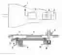
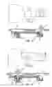
DESCRIPTION OF THE DRAWINGSFIG. 1 is prior art showing the original shifter position.
FIG. 2 is the section AA is showing the pertinent components of the prior art.
FIG. 3 is the new design showing a typical relocation of shifter position.
FIG. 4 is the section BB is showing the pertinent components of the relocated shifter position.
DETAILED DESCRIPTION OF INVENTIONThe invention will be referenced to the accompanying drawing. To understand in full detail, please refer to the accompanying drawing.
The shifter assembly (3) is removed and altered to detail (13).
The cover plate (2) is removed.
The original “front offset lever” (5 as shown in FIG. 2) is removed and replaced by the redesigned front offset lever and shifter socket combination (10 as shown in FIG. 4).
An additional isolator cup (9) is used in the newly designed detail (10).
The original shifter rail (7 as shown in FIG. 2) is replaced with the shorter forward shifter rail (11 as shown in FIG. 4) to allow operational room for the repositioned shifter assembly (3).
A rear shifter rail (12 as shown in FIG. 4) is mounted to provide rigidity and connection with the rear offset lever (8).
Items 8, 10, 11, and 12 are pinned together with roll pins (4 as shown in FIG. 4) to provide an integral assembly.
The altered shifter (13) is assembled to the forward section and couples with the front offset lever combination (10).
The altered shifter assembly (10) allows for transfer of the shifting movements to the internal transmission mechanism (6 as shown in FIG. 4).
A redesigned cover plate (14) is assembled to the rear access port of the transmission.
Claims
1. A new design of the “front offset lever” to allow multiple positioning of the shifter assembly.
2. The new design allows for adaptation of standard or alternate shifter assemblies.
3. A relocation of the shifter position to allow adaptation of a 6 speed transmission to a variety of auto platforms.
4. The relocation is effected with no degradation of the transmission.
5. The required movements and distances for shifting are the same as for those in the original position.
Images & Drawings included:
Sources:
- United States Patent and Trademark Office - verify current appl. status at the USPTO↗
Recent applications in this class:
- » 20250155017 2025-05-15
MECHANICAL-ELECTRICAL-HYDRAULIC HYBRID TRANSMISSION DEVICE AND CONTROL METHOD THEREOF - » 20200040990 2020-02-06
FLEXIBLE, LINEAR, ELECTRIC ACTUATOR FOR AUTOMOTIVE APPLICATIONS - » 20180135748 2018-05-17
Assembly for regulating ground speed of vehicle - » 20150308567 2015-10-29
GEAR SHIFTER ARRANGEMENT - » 20150276052 2015-10-01
Transmission with commanded gear shift monitoring logic - » 20150260283 2015-09-17
Gearshift mechanism and working vehicle - » 20150192204 2015-07-09
Dampers at the main shift rod - » 20150184743 2015-07-02
Transmission control device - » 20150167841 2015-06-18
Gear-shifting device for vehicle - » 20140088846 2014-03-27
Bicycle shifting method