Light source structure
US20050157519A1
2005-07-21
10/945,213
2004-09-20
✅ Patent granted
US 7,150,556 B2
2006-12-19
-
-
Renee Luebke | Julie A. Shallenberger
2025-01-04
Abstract:
A light source structure includes a guidelight plate, a visible-light member disposed on at a first side of the guidelight plate, and an infrared-radiation member disposed on a second side of the guidelight plate. Whereby the visible-light member and the infrared-radiation member reveal a surface of a predetermined object, and provide revealed images that is capable of combining as a complete image. According to particular locations of the visible-light member and the lighting components, the light source structure is thin and cheap, with an additional benefit with high uniformity thereof.
Interested in similar patents?
Get notified when new applications in this technology area are published.
Classification:
G02F1/1335 IPC
Devices or arrangements for the control of the intensity, colour, phase, polarisation or direction of light arriving from an independent light source, e.g. switching, gating or modulating; Non-linear optics for the control of the intensity, phase, polarisation or colour based on liquid crystals, e.g. single liquid crystal display cells; Constructional arrangements; Operation of liquid crystal cells; Circuit arrangements; Constructional arrangements; Manufacturing methods Structural association of cells with optical devices, e.g. polarisers or reflectors
F21V7/04 IPC
Reflectors for light sources Optical design
G02B6/0068 » CPC main
Light guides specially adapted for lighting devices or systems the light guides being planar or of plate-like form characterised by the light source being coupled to the light guide Arrangements of plural sources, e.g. multi-colour light sources
H04N1/02815 » CPC further
Scanning, transmission or reproduction of documents or the like, e.g. facsimile transmission; Details thereof; Details of scanning heads ; Means for illuminating the original for picture information pick-up Means for illuminating the original, not specific to a particular type of pick-up head
H04N1/02855 » CPC further
Scanning, transmission or reproduction of documents or the like, e.g. facsimile transmission; Details thereof; Details of scanning heads ; Means for illuminating the original for picture information pick-up; Means for illuminating the original, not specific to a particular type of pick-up head using an elongated light source, e.g. tubular lamp, LED array in combination with a light guide, e.g. optical fibre, glass plate
H04N1/02865 » CPC further
Scanning, transmission or reproduction of documents or the like, e.g. facsimile transmission; Details thereof; Details of scanning heads ; Means for illuminating the original for picture information pick-up; Means for illuminating the original, not specific to a particular type of pick-up head using an elongated light source, e.g. tubular lamp, LED array using an array of light sources or a combination of such arrays, e.g. an LED bar
H04N1/0287 » CPC further
Scanning, transmission or reproduction of documents or the like, e.g. facsimile transmission; Details thereof; Details of scanning heads ; Means for illuminating the original for picture information pick-up; Means for illuminating the original, not specific to a particular type of pick-up head using an elongated light source, e.g. tubular lamp, LED array using a tubular lamp or a combination of such lamps
Description
CROSS-REFERENCE TO RELATED APPLICATIONSThis application is a Continuation-in-Part of application Ser. No. 10/759,951, filed 16 Jan. 2004, and entitled LIGHT SOURCE STRUCTURE.
BACKGROUND OF THE INVENTION1. Field of the Invention
The present invention relates to a light source structure, and particularly relates to a light source structure adopted for a scanner for scanning documents, negative or positive films.
2. Background of the Invention
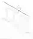
With reference to FIGS. 1 and 2, a conventional light source structure adopted for a conventional scanner includes a guidelight plate 9 and a lighting unit 8. The lighting unit 8 includes a lamp 80 and an infrared-radiation member 81, which are composed of a circuit board 82, a plurality of LEDs and resistors disposed on the circuit board 82. The guidelight plate 9 is flat, rectangular and transparent, and has a cutout 90 partially formed at an elongated side 91 thereof for receiving the lamp 80 therein. The lighting components 81 are set to be adjacent to the lamp 80 and the elongated side 91 of the guidelight plate 9 simultaneously, so that the lighting components 81 and the lamp 80 are together disposed on the same side, the elongated side 91, of the guidelight plate 9. The LEDs provide visible light to be an auxiliary lighting in order to enhance the luminance, while the lamp 80 provides the primary lighting.
The lighting components 81 and the lamp 80 are together disposed on the elongated side 91 of the guidelight plate 9 in an up-and-down manner, light from the LEDs travels longer than that from the lamp 80 due to the different thickness thereof. A uniformity of the guidelight plate 9 cannot increase thereby. In addition, the light from the lamp 80 is interfered by a corner around the cutout 90 to further decrease the uniformity of the guidelight plate 9. For mating with the lamp 80, the guidelight plate 9 should be thick enough, and materials and costs will be consumed.
Although the LEDs and the lamp 80 provide the luminance of the conventional light source structure simultaneously, there are some scanning problems in the conventional scanner, such as vague images or low contrast. The conventional light source structure is originally applied not only to the conventional scanner, also to various electronic apparatus that needs optical sensing devices. Obviously, the problems, vague images or low contrast, restrict applications and functions of the conventional light source structure.
Hence, an improvement over the prior art is required to overcome the disadvantages thereof.
SUMMARY OF INVENTIONThe primary object of the invention is therefore to specify a light source structure to provide visible lighting and infrared radiation for a clear and complete image to meet various requirements.
The secondary object of the invention is therefore to specify a light source structure with a thin plate, which thickness is equivalent to that of a visible-light member, to shrink the size thereof and to save materials and costs.
The third object of the invention is therefore to specify a light source structure with a high luminance and a high uniformity thereof without different traveling due to a cutout that is used to receive a CCFL conventionally.
According to the invention, this object is achieved by a light source structure includes a guidelight plate, a visible-light member disposed on at a first side of the guidelight plate, and an infrared-radiation member disposed on a second side of the guidelight plate. Whereby the visible-light member and the infrared-radiation member reveal a surface of a predetermined object, and provide revealed images that is capable of combining as a complete image.
To provide a further understanding of the invention, the following detailed description illustrates embodiments and examples of the invention. Examples of the more important features of the invention thus have been summarized rather broadly in order that the detailed description thereof that follows may be better understood, and in order that the contributions to the art may be appreciated. There are, of course, additional features of the invention that will be described hereinafter and which will form the subject of the claims appended hereto.
BRIEF DESCRIPTION OF THE DRAWINGSThese and other features, aspects, and advantages of the present invention will become better understood with regard to the following description, appended claims, and accompanying drawings where:
FIG. 1 is a decomposition view according to a conventional light source structure;
FIG. 2 is a cross-sectional profile according to the conventional light source structure;
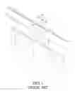
FIG. 3 is a decomposition view of a light source structure according to the present invention;
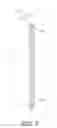
FIG. 4 is a perspective view of the light source structure according to the present invention;
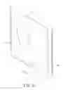
FIG. 5 is a cross-sectional profile of the light source structure according to the present invention; and
FIG. 6 is a perspective view of the light source structure of another embodiment according to the present invention.
DETAILED DESCRIPTION OF THE EMBODIMENTSReferring to FIGS. 3 to 5, a light source structure according to the present invention includes a lighting unit 1 and a guidelight plate 2. The lighting unit 1 has a visible-light member 10 and an infrared-radiation member 11 arranged on different sides of the guidelight plate 2. The visible-light member 10 is a CCFL (Cold Cathode Florescent Lamp) in FIG. 3; in an alternative manner, the visible-light member 10 can include a board and a plurality of LEDs that provide visible light and dispose on the board (not shown). The infrared-radiation member 11 includes a circuit board 12, a plurality of LEDs (Light Emitting Diode) 13 and resistors 14 arranged on the circuit board 12. The LEDs 13 provides infrared radiation that is invisible to human. Therefore, the visible-light member 10 provides primary, visible lighting onto a predetermined object via the guidelight plate 2, in order to get a first image sensed by an optical sensor (a normal step). As is known to all, infrared imaging is used to clearly detect materials, wrinkles or blurs around an object. This gives a more complete picture of the whole object. The LEDs 13 provides infrared, invisible radiation to show more details on the predetermined object to get a second image that usually is monochromatic. For ease to get a compete image, a processor (not shown) combines the first and second images to be a whole one. Or, if the wrinkles or the dirt on the predetermined object are not proper to reveal apparently, the infrared-radiation member 11 is controlled to pause, so as to get the first image only.
The visible-light member 10 and the infrared-radiation member 11 respectively connect power cores 15 for power supply. The guidelight plate 2 is flat, rectangular and transparent, and has two elongated sides 20 opposite each other. The visible-light member 10 and the infrared-radiation member 11 are respectively disposed on the two elongated sides 20 in FIG. 4.
When the light source structure is in use, what provides light is the visible-light member 10 provides uniformity, without different traveling due to the cutout 90 that is used to receive the lamp 80 conventionally.
With respect to FIG. 6, another embodiment according to the present invention, the visible-light member 10 disposes on a side 0′ of the guidelight plate 0′, and two infrared-radiation members 11′ are disposed respectively on two lateral sides 0′ of the guidelight plate 0′. Wherein the two lateral sides 0′ are perpendicular to the side 0′.
According to the present invention, the visible-light member 1 (1′) and the infrared-radiation member 11 (11′) are respectively disposed on sides of the guidelight plate 0 (0′). The light source structure needs no recess formed in the guidelight plate 2 for receiving the visible-light member 10; thus the guidelight plate 2 has a thin size to shrink a volume thereof and to save costs thereby.
It should be apparent to those skilled in the art that the above description is only illustrative of specific embodiments and examples of the invention. The invention should therefore cover various modifications and variations made to the herein-described structure and operations of the invention, provided they fall within the scope of the invention as defined in the following appended claims.
Reference:
conventional light source structure
- lighting unit 8
- lamp 80
- lighting component 81
- circuit board 82
- guidelight plate 9
- cutout 90
- elongated side 91
the present invention light source structure - lighting unit 1
- visible-light member 1, 1′
- infrared-radiation member 11, 11′
- circuit board 12
- power core 15
- guidelight plate 0, 0′
- side 0, 0′
Claims
1. A light source structure comprising:
a guidelight plate;
a visible-light member disposed on at a first side of the guidelight plate; and
an infrared-radiation member disposed on a second side of the guidelight plate;
whereby the visible-light member and the infrared-radiation member reveal a surface of a predetermined object, and provide revealed images that is capable of combining as a complete image.
2. The light source structure as claimed in claim 1, wherein the visible-light member is a CCFL.
3. The light source structure as claimed in claim 1, wherein the visible-light member includes a plurality of LEDs providing visible light.
4. The light source structure as claimed in claim 1, wherein the lighting infrared-radiation member includes a circuit board, a plurality of LEDs providing infrared radiation and arranged on the circuit board, and resistors disposed on the circuit board.
5. The light source structure as claimed in claim 1, wherein the lighting infrared-radiation member and the visible-light member are disposed on opposite, elongated sides of the guidelight plate.
Images & Drawings included:


Sources:
- United States Patent and Trademark Office - verify current appl. status at the USPTO↗
Similar patent applications:
- » 20210336104
LIGHT SOURCE STRUCTURE, ELECTRONIC DEVICE AND MANUFACTURING METHOD OF LIGHT SOURCE STRUCTURE - » 20060290267
High efficiency mercury-free flat light source structure, flat light source apparatus and driving method thereof - » 20100039040
Driving method for high efficiency mercury-free flat light source structure, and flat light source apparatus - » 20050128767
Light source structure of light emitting diode - » 20200049336
Light source structure and lighting device - » 20150349211
LED light source packaging method, LED light source package structure and light source module - » 20090279282
Light source holding structure, a light source holding member, a light source holding unit, and a display device - » 10339574
Structured light source - » 20050094416
Light source structure - » 10317062
Plane light source structure for planar display
Recent applications in this class:
- » 20250237805 2025-07-24
BACKLIGHT UNIT AND DISPLAY APPARATUS HAVING THE SAME - » 20250231336 2025-07-17
LIGHTING DEVICE AND VEHICULE COMPONENT COMPRISING SUCH A LIGHTING DEVICE - » 20250224552 2025-07-10
FRONT LIGHT FOR USE WITH REFLECTIVE DISPLAYS - » 20250199233 2025-06-19
LIGHT GUIDE ASSEMBLY FOR A VEHICLE - » 20250147223 2025-05-08
BACKLIGHT MODULE, VIEWING MODE SWITCHING METHOD THEREOF, AND DISPLAY DEVICE INCLUDING THE BACKLIGHT MODULE - » 20250138237 2025-05-01
LIGHT EMITTING MODULE - » 20250093572 2025-03-20
Backlight Module and Display Device - » 20250085470 2025-03-13
DISPLAY DEVICE AND LIGHT MODULE THEREOF - » 20250020858 2025-01-16
SYSTEMS AND METHODS FOR LIGHTING AN E-PAPER DISPLAY - » 20250004190 2025-01-02
MICROREPLICATED OPTICAL FILM