Small air pump
US20050158189A1
2005-07-21
10/758,087
2004-01-16
Abstract:
A small air pump and particularly a small air pump adopted for use on small fish bowls to provide required air includes a solenoid assembly and an air chamber assembly. The solenoid assembly can generate intermittent electromagnetic force to pump air in the air chamber assembly to supply air to a small fish bowl.
Interested in similar patents?
Get notified when new applications in this technology area are published.
Classification:
F04B43/04 » CPC main
Machines, pumps, or pumping installations having flexible working members having plate-like flexible members, e.g. diaphragms Pumps having electric drive
Description
BACKGROUND OF THE INVENTION1. Field of the Invention
The present invention relates to a small air pump and particularly to a small air pump adopted use on a small fish bowl to provide required air in a compact size and lower noise.
2. Description of the Prior Art
The air pump for conventional fish bowls (or aquariums) mainly includes a case 2 consisting of an upper lid 21 and a base 22 that are coupled together. The case 2 has a hollow housing compartment 20 for holding a device body 1 of an air pump. The device body 1 may operate to deliver air through an air duct 11 to a fish bowl (or aquarium) to supply air required. Such a structure only suitable for a medium or large fish bowl (or aquarium). It is not desirable for small fish bowls, as it is too bulky and takes too much tabletop space. Moreover, the operation noise is too loud and often affects people's work or study. Such an air pump also generates too much air which is also not desirable for small fish bowls. As the water in the small fish bowl will be disturbed too much and result in too much oxygen content, and will have ill effect for fish breeding.
SUMMARY OF THE INVENTIONIn view of the aforesaid disadvantages, the present invention aims to provide a small air pump for small fish bowls to resolve the problems of too much noise and bulky size occurred to the conventional air pumps.
The primary object of the invention is to provide a small air pump that mainly includes a solenoid assembly and an air chamber assembly. The solenoid assembly may generate intermittent electromagnetic force to pump the air in the air chamber assembly thereby to provide required air for a small fish bowl in a compact size and lower noise.
The foregoing, as well as additional objects, features and advantages of the invention will be more readily apparent from the following detailed description, which proceeds with reference to the accompanying drawings.
BRIEF DESCRIPTION OF THE DRAWINGSFIG. 1 is a sectional view of a conventional air pump.
FIG. 2 is a perspective view of the invention.
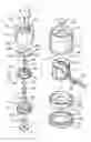
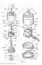
FIG. 3 is an exploded view of the invention.
FIG. 4 is a perspective view of the air chamber seat of the invention.
FIG. 5 is a schematic view of the invention in a use condition.
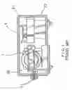
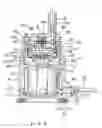
FIG. 6 is a sectional view of the invention in an operating condition.
DESCRIPTION OF THE PREFERRED EMBODIMENTReferring to FIGS. 2, 3 and 4, the invention mainly includes a solenoid assembly 3 and an air chamber assembly 4.
The solenoid assembly 3 includes:
-
- a pliable pad 31 which has an annular pad ring 310 with a center opening 311 and a circular trough 312 on the annular pad ring 310;
- a bottom shell 32 which has a lower retaining rim 321 extending downwards from the bottom with a diameter slightly smaller than the center opening 311 and an upper retaining rim 322 extending upwards from the perimeter. The upper retaining rim 322 has a plurality of anchor struts 323 on the inner wall and a lower anchor seat 325 on one side. The lower anchor seat 325 has a lower notch 324;
a solenoid element 33 which is a standard element connecting to conductive wires 331. When the conductive wires 331 are plugged to an electric power supply, a magnetic disc 332 located on the top end will generate magnetic force;
-
- an upper shell 34 which is coupled with the bottom shell 32 for housing the case of the solenoid element 33. It has a hollow housing compartment 341 at an upper portion that has an inner wall with a plurality of L-shaped troughs formed on thereon. It has a bottom section with a jutting rim 343 slightly smaller than the upper retaining rim 322 of the bottom shell 32. The jutting rim 343 has a plurality of troughs 344 corresponding to the anchor struts 323 of the bottom shell 32. The upper shell 34 further has an upper anchor seat 345 which has an upper notch 346 corresponding to the lower notch 324 of the lower anchor seat 325 of the bottom shell 32;
- a lower polar plate 35 coupled on the magnetic disc 332 of the solenoid element 33 to evenly distribute the magnetic force and expand the range of the magnetic force.
The air chamber assembly 4 includes:
-
- an upper polar plate 41 corresponding to the lower polar plate 35 has an internal screw hole 411 in the center;
- a rubber cap 42 made from rubber and formed in a cap-shape having a housing chamber 420 which has an inner flange 421 at a lower section, and a round hole 422 on the bottom to couple with a bolt A and a washer B to fasten to the lower polar plate 41;
- an air chamber seat 43 which has a flange 431 extending from the bottom rim to couple with the inner flange 421 of the rubber cap 42. It also has an internal screw hole 432 in the center, and an air discharge chamber 433 and an air intake chamber 434 formed respectively on an upper side and a lower side in the opposite directions. The air discharge chamber 433 and the air intake chamber 434 have respectively an air vent 435 and 436 on one side to couple respectively with a spacer 47 and 46, and a plug 45 and 44 to restrict airflow passing through the air vents 435 and 436 in one way. The air chamber seat 43 further has at least one anchor strut 437 on the top section;
- an anchor plate 48 made of a pliable plate corresponding to the air chamber seat 43 and has a cut away notch 481 corresponding to the air vent 436 of the air intake chamber 434. There are at least one anchor hole 482 formed on two sides of the notch 481 to couple with the retaining struts 437 of the air chamber seat 43. The anchor plate 48 further has an air outlet 483 corresponding to the air discharge chamber 433, and a round hole 484 in the center corresponding to the internal screw hole 432 of the air chamber seat 43; and
- an air chamber cap 49 formed in a cylindrical barrel having at least one anchor hole 491 on the top and an air supply port 492 on one side to couple with an air duct 51 and an air inlet 493 on another side. The air chamber cap 49 also has a round hole 494 in the center to couple with the bolt A for fastening to the internal screw hole 432 of the air chamber seat 43, and at least one latch lug 495 on the outer surface of the bottom thereof to engage with the L-shaped troughs 342 to couple the air chamber cap 49 with the upper shell 34.
By means of the construction set forth above, and referring to FIGS. 5 and 6, when in use, the air pump of the invention may be placed on a location slightly higher than a fish bowl 5, and the air duct 51 is channeled in the fish bowl 5. When the invention is in operation, the solenoid element 33 is energized by electricity. An intermittent magnetic force will be generated on the magnetic disc 332. The lower polar plate 35 can expand the range of the magnetic force to attract the upper polar plate 41. As the rubber cap 42 is fastened to the upper polar plate 41 through the bolt A, it will be pulled downwards to extend the rubber cap 42 to a maximum condition. As a result, external air will be sucked in through the gap between the air chamber cap 49 and the upper shell 34, and flow through the air inlet 493 at the top end of the air chamber cap 49, the notch 481 of the anchor plate 48, the air vent 436 of the air chamber seat 43, and push the one way spacer 46 and enter the housing chamber 420 of the rubber cap 42 (meanwhile the air discharge chamber 433 is blocked by the one way spacer 47 to prevent air from counter flowing). When the magnetic force of the solenoid element 33 is interrupted, the rubber cap 42 is no longer attracted by the magnetic disc 332, the air in the housing chamber 420 is compressed to flow through the intake vent 435 and the one way spacer 47 is pushed to allow the air to flow into the air discharge chamber 433 (meanwhile the air intake chamber 434 is blocked by the one way spacer 46 to prevent the air from counter flowing), and the air flows through the air supply port 492 into the air duct 51. The sucking and discharging movements set forth above are operated repeatedly to provide air required in the fish bowl.
In summary, the air pump of the invention has a simple structure, small size, occupies a small space and consumes a small amount of electricity. It is especially desirable to supply air for small fish bowls.
Claims
1. A small air pump comprising a solenoid assembly and an air chamber assembly, wherein:
the solenoid assembly includes:
a pliable pad which has an annular pad ring with a center opening and a circular trough formed on the annular pad ring;
a bottom shell which has a lower retaining rim extending downwards from the bottom thereof slightly smaller than the center opening and an upper retaining rim extending upwards from the perimeter thereof;
a solenoid element which is a standard element connecting to conductive wires for plugging to an electric power supply to allow a magnetic disc located on the top end thereof to generate magnetic force;
an upper shell which is coupled with the bottom shell for housing the solenoid element having a hollow housing compartment at an upper portion that has an inner wall with a plurality of L-shaped troughs formed thereon, and a bottom section with a jutting rim slightly smaller than the upper retaining rim of the bottom shell; and
a lower polar plate coupled on the magnetic disc of the solenoid element to evenly distribute the magnetic force and expand the range of the magnetic force;
the air chamber assembly includes:
an upper polar plate corresponding to the lower polar plate;
a rubber cap made from rubber and formed in a cap-shape having a housing chamber which has a bottom fastening to the lower polar plate;
an air chamber seat which has a flange extending from the bottom rim to couple with the rubber cap, and an air discharge chamber and an air intake chamber formed respectively on an upper side and a lower side in opposite directions, the air discharge chamber and the air intake chamber having respectively an air vent on one side to couple respectively with a spacer and a plug to restrict airflow passing through the air vents in one way;
an anchor plate made of a pliable plate corresponding to the air chamber seat having a cut away notch corresponding to the air vent of the air intake chamber and an air outlet corresponding to the air vent of the air discharge chamber; and
an air chamber cap formed in a cylindrical barrel having an air supply port on one side of a top end to couple with an air duct, and an air inlet on another side thereof, the air chamber cap further having at least one latch lug on the outer surface of the bottom thereof to engage with the L-shaped troughs to couple the air chamber cap with the upper shell.
2. The small air pump of claim 1, wherein the upper retaining rim of the bottom shell has a plurality of anchor struts on the inner wall and a lower anchor seat on one side, the lower anchor seat having a lower notch.
3. The small air pump of claim 1, wherein the jutting rim of the upper shell has a plurality of troughs.
4. The small air pump of claim 1, wherein the upper shell has an upper anchor seat on the peripheral side.
Images & Drawings included:


Sources:
- United States Patent and Trademark Office - verify current appl. status at the USPTO↗
Similar patent applications:
- » 20060208613
Small piezoelectric air pumps with unobstructed airflow - » 20060208614
Small piezoelectric air pumps with unobstructed airflow - » 20070182286
Small piezoelectric air pumps with unobstructed airflow - » 20230400031
AIR PUMP DEVICE ADAPTED TO SMALL-SIZED INFLATABLE PRODUCT AND INFLATABLE PRODUCT - » 20080202125
Packaged small-duct, high-velocity air conditioner and heat pump apparatus
Recent applications in this class:
- » 20240426288 2024-12-26
Pulsatile Fluid Pump System - » 20240401583 2024-12-05
VALVE MODULE, FLUID CONTROL APPARATUS, AND ELECTRONIC APPARATUS - » 20240401582 2024-12-05
DIAPHRAGM PUMP WITH MULTIPLE DISCHARGE TUBES - » 20240271609 2024-08-15
MAGNETICALLY DRIVEN PRESSURE GENERATOR - » 20240183348 2024-06-06
PUMP - » 20240125314 2024-04-18
PROCESS FOR SENSORLESS DETECTION OF STROKE EXECUTION IN A MAGNETIC PUMP - » 20240044322 2024-02-08
Pumping system in the lab-on-a-chip field - » 20230349372 2023-11-02
Diaphragm pump - » 20230304486 2023-09-28
Electrochemical compressor - » 20230243347 2023-08-03
Electrically operated displacement pump control system and method