Method and apparatus for performing a slippage regulation in a continuously variable transmission
US20050197220A1
2005-09-08
11/070,928
2005-03-03
✅ Patent granted
US 7,258,636 B2
2007-08-21
-
-
Marcus Charles
2025-04-19
Abstract:
A method and apparatus for carrying out a drive belt slippage regulation in a continuously variable transmission. A driving disk set and a driven disk set are connected together for torque transfer by an endless torque-transmitting element in which a power ratio between the driving disk set and the driven disk set of a variable speed drive is set as a function of a safety margin value.
Assignee:
- LuK Lamellen und Kupplungsbau Beteiligungs KG 287 🇩🇪 Buhl, Germany
Interested in similar patents?
Get notified when new applications in this technology area are published.
Classification:
B60K31/042 » CPC main
Vehicle fittings, acting on a single sub-unit only, for automatically controlling vehicle speed, i.e. preventing speed from exceeding an arbitrarily established velocity or maintaining speed at a particular velocity, as selected by the vehicle operator including electrically actuated servomechanism including an electric control system or a servomechanism in which the vehicle velocity affecting element is actuated electrically and means for comparing one electrical quantity, e.g. voltage, pulse, waveform, flux, or the like, with another quantity of a like kind, which comparison means is involved in the development of an electrical signal which is fed into the controlling means where at least one electrical quantity is set by the vehicle operator
B60Q1/44 » CPC further
Arrangement of optical signalling or lighting devices, the mounting or supporting thereof or circuits therefor the devices being primarily intended to indicate the vehicle, or parts thereof, or to give signals, to other traffic for indicating braking action or preparation for braking, e.g. by detection of the foot approaching the brake pedal
B60Q11/00 » CPC further
Arrangement of monitoring devices for devices provided for in groups -
B60T8/885 » CPC further
Arrangements for adjusting wheel-braking force to meet varying vehicular or ground-surface conditions, e.g. limiting or varying distribution of braking force responsive to a speed condition, e.g. acceleration or deceleration with failure responsive means, i.e. means for detecting and indicating faulty operation of the speed responsive control means using electrical circuitry
B60T17/22 » CPC further
Component parts, details, or accessories of power brake systems not covered by groups , or , or presenting other characteristic features; Safety devices; Monitoring Devices for monitoring or checking brake systems; Signal devices
B60W10/04 » CPC further
Conjoint control of vehicle sub-units of different type or different function including control of propulsion units
B60W10/10 » CPC further
Conjoint control of vehicle sub-units of different type or different function including control of change-speed gearings
B60W10/11 » CPC further
Conjoint control of vehicle sub-units of different type or different function including control of change-speed gearings Stepped gearings
B60W30/18 » CPC further
Purposes of road vehicle drive control systems not related to the control of a particular sub-unit, e.g. of systems using conjoint control of vehicle sub-units, or advanced driver assistance systems for ensuring comfort, stability and safety or drive control systems for propelling or retarding the vehicle Propelling the vehicle
B60W30/1819 » CPC further
Purposes of road vehicle drive control systems not related to the control of a particular sub-unit, e.g. of systems using conjoint control of vehicle sub-units, or advanced driver assistance systems for ensuring comfort, stability and safety or drive control systems for propelling or retarding the vehicle; Propelling the vehicle Propulsion control with control means using analogue circuits, relays or mechanical links
B60W30/1884 » CPC further
Purposes of road vehicle drive control systems not related to the control of a particular sub-unit, e.g. of systems using conjoint control of vehicle sub-units, or advanced driver assistance systems for ensuring comfort, stability and safety or drive control systems for propelling or retarding the vehicle; Propelling the vehicle; Controlling power parameters of the driveline, e.g. determining the required power Avoiding stall or overspeed of the engine
B60W50/038 » CPC further
Details of control systems for road vehicle drive control not related to the control of a particular sub-unit, e.g. process diagnostic or vehicle driver interfaces; Ensuring safety in case of control system failures, e.g. by diagnosing, circumventing or fixing failures Limiting the input power, torque or speed
F02D41/042 » CPC further
Electrical control of supply of combustible mixture or its constituents; Circuit arrangements for generating control signals; Introducing corrections for particular operating conditions for stopping the engine
F16H61/12 » CPC further
Control functions within change-speed- or reversing-gearings for conveying rotary motion Detecting malfunction or potential malfunction, e.g. fail safe
F16H61/32 » CPC further
Control functions within change-speed- or reversing-gearings for conveying rotary motion; Generation or transmission of movements for final actuating mechanisms with at least one movement of the final actuating mechanism being caused by a non-mechanical force, e.g. power-assisted Electric motors actuators or related electrical control means therefor
F16H61/66272 » CPC further
Control functions within change-speed- or reversing-gearings for conveying rotary motion specially adapted for continuously variable gearings with endless flexible members characterised by means for controlling the torque transmitting capability of the gearing
G05B9/02 » CPC further
Safety arrangements electric
B60T2260/08 » CPC further
Interaction of vehicle brake system with other systems Coordination of integrated systems
B60T2270/413 » CPC further
Further aspects of brake control systems not otherwise provided for; Failsafe aspects of brake control systems Plausibility monitoring, cross check, redundancy
B60W10/06 » CPC further
Conjoint control of vehicle sub-units of different type or different function including control of propulsion units including control of combustion engines
B60W2510/0638 » CPC further
Input parameters relating to a particular sub-units; Combustion engines, Gas turbines Engine speed
B60W2540/10 » CPC further
Input parameters relating to occupants Accelerator pedal position
B60W2540/12 » CPC further
Input parameters relating to occupants Brake pedal position
B60W2710/065 » CPC further
Output or target parameters relating to a particular sub-units; Combustion engines, Gas turbines; Engine speed Idle condition
F02D41/22 » CPC further
Electrical control of supply of combustible mixture or its constituents Safety or indicating devices for abnormal conditions
F16H61/0021 » CPC further
Control functions within change-speed- or reversing-gearings for conveying rotary motion Generation or control of line pressure
F16H2061/0053 » CPC further
Control functions within change-speed- or reversing-gearings for conveying rotary motion Initializing the parameters of the controller
F16H2061/1208 » CPC further
Control functions within change-speed- or reversing-gearings for conveying rotary motion; Detecting malfunction or potential malfunction, e.g. fail safe with diagnostic check cycles; Monitoring of failures
F16H2061/1216 » CPC further
Control functions within change-speed- or reversing-gearings for conveying rotary motion; Detecting malfunction or potential malfunction, e.g. fail safe with diagnostic check cycles; Monitoring of failures Display or indication of detected failures
F16H2061/1232 » CPC further
Control functions within change-speed- or reversing-gearings for conveying rotary motion; Detecting malfunction or potential malfunction, e.g. fail safe Bringing the control into a predefined state, e.g. giving priority to particular actuators or gear ratios
F16H2061/126 » CPC further
Control functions within change-speed- or reversing-gearings for conveying rotary motion; Detecting malfunction or potential malfunction, e.g. fail safe characterised by the parts or units where malfunctioning was assumed or detected the failing part is the controller
F16H2061/1288 » CPC further
Control functions within change-speed- or reversing-gearings for conveying rotary motion; Detecting malfunction or potential malfunction, e.g. fail safe characterised by the parts or units where malfunctioning was assumed or detected the failing part is an actuator
F16H2061/283 » CPC further
Control functions within change-speed- or reversing-gearings for conveying rotary motion; Generation or transmission of movements for final actuating mechanisms with at least one movement of the final actuating mechanism being caused by a non-mechanical force, e.g. power-assisted Adjustment or calibration of actuator positions, e.g. neutral position
F16H2312/12 » CPC further
Driving activities Parking
F16H2312/16 » CPC further
Driving activities Coming to a halt
F16H2312/20 » CPC further
Driving activities Start-up or shut-down
F16H2342/042 » CPC further
Calibrating; Calibrating engagement of friction elements Point of engagement
Y10T74/11 » CPC further
Machine element or mechanism Tripping mechanism
F16H61/06 IPC
Control functions within change-speed- or reversing-gearings for conveying rotary motion; Smoothing ratio shift by controlling rate of change of fluid pressure
F16H59/04 IPC
Control inputs to control units of change-speed-, or reversing-gearings for conveying rotary motion; Selector apparatus Ratio selector apparatus
F16H61/662 IPC
Control functions within change-speed- or reversing-gearings for conveying rotary motion specially adapted for continuously variable gearings with endless flexible members
Description
CROSS-REFERENCE TO RELATED APPLICATIONThis is a continuation of International Application Serial No. PCT/DE2003/002913, with an international filing date of Sep. 3, 2003, and designating the United States, the entire contents of which is hereby incorporated by reference to the same extent as if fully rewritten.
BACKGROUND OF THE INVENTION1. Field of the Invention
The present invention relates to a method and an apparatus for performing slippage control in a continuously variable transmission, particularly an endless belt transmission having a driving disk set and a driven disk set that are coupled to one another by an endless belt means for transmitting torque.
2. Description of the Related Art
Continuously variable transmissions such as, for example, endless belt transmissions, are known in automotive technology, and usually have a driving disk set and a driven disk set that are coupled to one another by means of an endless belt for transmitting torque. If the contact pressure on the disk sets is freely adjustable, it is helpful for the transmission ratio control in an endless belt transmission if the precise course of the power ratio as a function of a margin of safety or a safety factor is known. In certain driving situations, for example in the case of wheel-side impacts or the like, it is necessary for the safety factor to be increased. That cannot be taken into account in the transmission ratio control in the known endless belt transmissions, so that the effects of the changed power ratios on the transmission ratio of the variable speed drive cannot be reduced or eliminated. For that reason comfort in the motor vehicle can be detrimentally affected.
The object of the invention is to propose a method and an apparatus for further optimizing the transmission ratio control in a continuously variable transmission.
SUMMARY OF THE INVENTIONThat object can be procedurally achieved by a method for performing a slippage regulation in a continuously variable transmission, particularly an endless belt transmission, in which a driving disk set and a driven disk set that are coupled to one another by an endless belt means for transmitting torque, in which the power ratio (zeta) between the driving disk set and the driven disk set of a variable speed drive is learned as a function of the margin of safety. In that way an adaptation of the power ratio between the driving and driven disk sets of a variable speed drive as a function of the safety criteria (margin of safety) in a motor vehicle can be realized. Thereby the transmission ratio control, particularly in continuously variable transmissions, can be improved substantially.
The margin of safety is thereby designated as the power ratio at a current operating point between the actual contact force and the force at which a slippage of the belt means occurs. If, for example, the margin of safety assumes the value 1.0 it means that the slippage point of the belt means has been reached.
It is possible to determine the slippage point in advance. That can result, for example, by means of a superposition of an oscillation of the contact pressure and a cross-correlation between the rotational speeds of the disk sets, or the like. In the method in accordance with the invention, a reduction of the margin of safety begins at a very high contact pressure safety margin when the slippage point is known. That can be carried out until the slippage point is reached, or also until the instant shortly before the slippage point. That mode of operation can preferably be realized through a reduction of the contact pressure, for example, on the driven disk set. The transmission ratio control can thereby remain active at the same time, for example, and the change in the power ratios or the zeta value can be adjusted by a corresponding control of the disk set pressures.
The zeta value or the power ratio between the driving disk set and the driven disk set can be determined or calculated by knowledge of the rotational speed, the transmission ratio, and the disk set pressures or the control variables for the disk sets. The corresponding zeta values can preferably be saved as a function of the safety margin. The-power ratio can then be preliminarily controlled in an advantageous way to always make possible an optimal contact pressure with a sufficient safety margin.
Within the scope of a further development of the invention, it can be provided that the method is preferably carried out at quasi-static operating conditions with constant safety margin and/or with an intentional slow reduction in safety margin. Those operating conditions preferably are usually within the overdrive range (OD) during constant speeds. Because the required pressure is a function of the input torque, and consequently upon the engine torque, the engine torque should not be too high, in order to operate within the greatest possible safety margin range. A range of between 50 and 100 Nm is preferably utilized. However, other ranges and operating conditions are also possible.
According to a further arrangement, the adaptation pursuant to the invention need not be carried out continuously. It is also possible to operate it in stages or the like. Consequently, a transmission ratio point in the transmission can be successively carried out, for example, with different safety margins. The values of the power ratio (zeta) determined at the respective operating points can be stored in a corresponding memory table or the like, and/or can also be utilized in a parametric model. By means of that adaptation an individual adjustment of the transmission ratio regulation to the respective transmission is possible.
It is also conceivable in the proposed method to store or save the zeta value as a function of the safety margin and the transmission ratio for adjustment. In that way a characteristic field can then be adjusted instead of a characteristic line.
According to an advantageous further arrangement, a suitable estimation of the pressures in the disk sets can also be carried out. It is necessary to know all the power components in order to calculate the zeta value. Aside from the spring forces, forces are also taken into consideration that are calculated based on the static and dynamic pressures. It is particularly advantageous if those pressures are known. In the method in accordance with the invention it is, however, not absolutely necessary to know those static pressures, because respective assumptions about average characteristic lines of the hydraulic valves are sufficient. Because the control current of the hydraulic valves is known, a theoretical pressure value can be calculated from that value. The error between an approximate and the actual valve characteristic line can be compensated for by preferably utilizing those approximate valve characteristic lines in the control of the disk sets. Thereby a variation can be compensated for in the simplest way.
Within the scope of a further arrangement of the present invention, it can be provided that in the method in accordance with the invention a maximum zeta is calculated, preferably during the operation of the motor vehicle. For a fixed contact pressure on the driven disk set the input torque can be increased in such a way that it causes a slippage of the belt means of the transmission.
It is also possible to keep the input torque constant and thereby the contact pressure is reduced. The power ratio (zeta) increases thereby at first and decreases then again before slippage of the belt means (slippage point). The interval from the maximum value of zeta to the slippage point lies at about 10%-30% as a function of the transmission ratio. That interval, as a rule, is independent of the contact pressure.
It has been shown that an operation that lies within the left range of the maximum zeta is particularly advantageous for the transmission. It is possible during operation, for example, to plot or store the characteristics of the power ratios during a reduction of the contact pressure. If it is determined that the maximum zeta has shifted to a defined contact pressure, the actual pressure requirement has changed.
Corresponding corrections of the operating parameters can be carried out with the known maximum values of zeta in order to ensure that the contact pressure is realized in the desired operating ranges (left from maximum value of zeta).
Preferably, with the method in accordance with the invention the operating parameters of the maximum values of zeta, for example, the safety margin and/or the transmission ratio, can be saved.
By means of the proposed correction of the control parameters, particularly the driveability or the driving comfort are improved substantially in vehicles having continuously variable transmissions. Further, disruptive influences can also be considerably reduced by the zeta value. Moreover, with the method in accordance with the invention a monitoring of the actual contact pressure requirement is realized.
Furthermore, the underlying object of the invention can also be achieved by an apparatus for carrying out a slippage regulation in a continuously variable transmission, in particular an endless belt transmission, in which a driving disk set and a driven disk set are coupled to one another by an endless belt means for torque transmission, especially for carrying out the proposed method, in which a device is provided for learning a power ratio (zeta) between the driving disk set and the driven disk set of a variable speed drive as a function of a safety value.
BRIEF DESCRIPTION OF THE DRAWINGSFurther advantages and advantageous arrangements result from the dependent claims and the following described drawings in which:
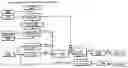
FIG. 1 is a flow diagram of a possible arrangement of the invention, and
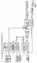
FIG. 2 is a graph with the representation of the maximum zeta measurement.
DESCRIPTION OF THE PREFERRED EMBODIMENTSA suitable method to provide an estimate of the pressures in the disk sets is represented in FIG. 1 in the form of a flow diagram. For the calculation of the zeta value, knowledge of all the force components is necessary. In addition to the spring forces, forces that are calculated from the static and dynamic pressures are also taken into consideration.
In the proposed estimate, respective assumptions about average characteristic lines of the hydraulic valves are utilized. Since the control current of the hydraulic valves is known, a theoretical pressure value can be calculated from that value. The error between the approximated and the actual valve characteristic line is compensated by utilizing those approximated valve characteristic lines for controlling the disk sets.
In FIG. 2 the characteristics of zeta (A), the contact pressure (B) on the driven disk set, the initial motor torque (C), and the safety margin (D) are represented.
In the determination of the maximum zeta value in accordance with the invention, the input torque for an almost constant contact pressure on the driven disk set can be increased in such a way that it approaches a slippage of the belt means of the transmission. After the maximum zeta, the slippage point becomes apparent on the basis of a reduction of the zeta value. Overall a particularly advantageous operation results for the continuously variable transmission when values are utilized that lie before the maximum zeta.
Claims
1. A method for performing a slippage regulation in a continuously variable transmission having a driving disk set and a driven disk set that are coupled to one another by a belt means for transmitting torque, said method comprising the steps of: detecting an input power level applied to a driving disk set and an output power level delivered by a driven disk set operatively coupled to the driving disk set; and determining a power ratio (zeta) between the driving disk set and the driven disk set of a variable speed drive based upon a safety margin value.
2. A method in accordance with claim 1, wherein the power ratio at an actual operating point between the actual contact pressure and the force with which a slippage of the belt occurs is utilized as the safety margin value.
3. A method in accordance with claim 1, including the step of reducing the contact pressure at a known slippage point on the driven disk set until shortly before the belt means reaches the slippage point.
4. A method in accordance with claim 3, wherein a transmission ratio control at the variable speed drive remains active during the reduction of the contact pressure, and a change of the contact pressure is compensated by a corresponding control of the contact pressure on at least one disk set.
5. A method in accordance with claim 1, including the step of storing the power ratio as a function of the safety margin.
6. A method in accordance with claim 1, wherein the power ratio determination is carried out during quasi-static operating conditions of the transmission.
7. A method in accordance with claim 6, including the step of utilizing an operating condition in the overdrive range (OD) during constant driving as the quasi-static operating condition.
8. A method in accordance with claim 1, wherein the power ratio (zeta) is adapted sectionally.
9. A method in accordance claim 1, wherein a transmission ratio condition of the variable speed drive is driven with different successive timewise values of the power ratio.
10. A method in accordance with claim 9, wherein the values of the power ratio (zeta) determined with regard to the respective operating conditions are stored.
11. A method in accordance with claim 1, wherein the power ratio (zeta) is saved as a function of the safety margin and the transmission ratio of the variable speed drive.
12. A method in accordance claim 1, including the step of estimating the pressure in the two disk sets by calculating a theoretical pressure value from known control currents of hydraulic valves operatively associated with the disk sets.
13. A method in accordance with claim 1, including the step of calculating a maximum of the power ratio (zeta) during moving operation of the motor vehicle.
14. A method in accordance with claim 13, wherein at a predetermined contact pressure on the driven disk set an input engine torque is increased so that a slippage of the belt means of the transmission is approached.
15. A method in accordance with claim 13, wherein the input engine torque is kept constant and the contact pressure is reduced.
16. A method in accordance with claim 13, wherein the operating parameters of the transmission are corrected with the learned maximum zeta values to ensure an optimum contact pressure.
17. Apparatus for performing a slippage regulation in a continuously variable transmission, in which a driving disk set and a driven disk set are coupled to one another by a belt means for transmitting torque, wherein an arrangement is provided for learning a power ratio (zeta) between the driving disk set and the driven disk set of a variable speed drive as a function of a safety margin value.
18. A method in accordance with claim 9, wherein the values of the power ratio (zeta) determined with regard to the respective operating conditions are utilized in a parametric model.
Images & Drawings included:
Sources:
- United States Patent and Trademark Office - verify current appl. status at the USPTO↗
Recent applications in this class:
- » 20200269689 2020-08-27
ECO-CRUISE: FUEL-ECONOMY OPTIMIZED CRUISE CONTROL - » 20150014075 2015-01-15
Velocity-regulating system having a touch-sensitive control element - » 20100318273 2010-12-16
Method and apparatus for controlling traveling speed of a vehicle - » 20090321229 2009-12-31
"TURN-SIGNAL SWITCH FOR A MOTOR VEHICLE WHICH HAS AN ADAPTIVE CRUISE CONTROL" - » 20080190681 2008-08-14
Operator Control Device For A Driver Assistance System For A Motor Vehicle - » 20080006462 2008-01-10
Method and arrangement for the speed control of a motor vehicle and operator-controlled element - » 20070255479 2007-11-01
Cruise control device - » 20050257976 2005-11-24
Motor vehicle cruise control speed memory system - » 20050247497 2005-11-10
One-touch cruise control system - » 20050209047 2005-09-22
Drive train and method for controlling and/or regulating a drive train
Recent applications for this Assignee:
- » 20110155533 2011-06-30
Hydraulic system with a regulating circuit for controlling a motor vehicle transmission with automated actuation of clutches - » 20110056790 2011-03-10
Friction clutch having a wear adjuster - » 20100317473 2010-12-16
Continuously variable transmission - » 20100258399 2010-10-14
Friction clutch - » 20100258192 2010-10-14
Method for actuating a hydraulic servo system - » 20100234152 2010-09-16
Conical disk pair for a belt-driven conical-pulley transmission - » 20100170765 2010-07-08
Clutch unit - » 20100071788 2010-03-25
Hydraulic system with a pressure reducing valve - » 20100071437 2010-03-25
Calibration tool for fabricating disk springs - » 20090280952 2009-11-12
Method for operating a continuously variable conical pulley transmission