Optical disc storing case
US20050279656A1
2005-12-22
10/870,417
2004-06-16
Abstract:
An optical disk storing case, in which an optical disk can be easily stored, and can be taken out easily and positively and there is no fear that the optical disk will be curved or damaged when it is taken out. A pair of resilient tongue pieces are arranged inside the case in such a way that their extremity ends are confronted with each other. Protrusions arranged at each of the extremity ends are confronted with each other to form a column-like disk engaging means. Then, the resilient tongue pieces are connected to the case bottom surface by ribs protruded at both sides thereof, and when the extremity ends of the resilient tongue pieces are pushed down, their rear ends are sprung up.
Interested in similar patents?
Get notified when new applications in this technology area are published.
Classification:
G11B33/0427 » CPC main
Constructional parts, details or accessories not provided for in the other groups of this subclass; Cabinets; Cases; Stands; Disposition of apparatus therein or thereon modified to store record carriers for storing discs; Single disc boxes for discs without cartridge comprising centre hole locking means
Description
BACKGROUND OF THE INVENTION1. Field of the Invention
This invention relates to a case, and more particularly to an optical disc storing case for containing an optical disc, such as: a digital videodisc (DVD) or a compact disk (CD).
2. Description of the Prior Arts
In addition to the numerousness of storage capacity, since the appearance is small, the optical disk has spread widely as a record carrier of various information. Conventionally, as a container, which store the optical disk, it is called a jewel box and the box-like closing motion type case made from a rigid plastic.
Such case has carbon button-like member that engages with the feedhole of an optical disk, and contains an optical disk by inserting the feedhole of an optical disk in the above-mentioned carbon button-like member. And when removing the optical disk from the case, by pushing the above-mentioned carbon button-like member, engagement of the feedhole of an optical disk is canceled and an optical disk is usually lifted up.
However, since the feedhole of an optical disk had fitted into the carbon button-like member exactly, the user has to lift the optical disc up by holding the periphery section of an optical disk and take it out of the case. In this case, the optical disk will curve in the impossible direction. Thus, the recording surface is damaged or there is a possibility of destroying the content of record in the optical disc.
The present invention has arisen to mitigate and/or obviate the afore-described disadvantages of the conventional optical disc storing case.
SUMMARY OF THE INVENTIONThe primary object of the present invention is to provide an optical disc storing case in which an optical disc can be easily stored, and can be taken out easily, and the optical disc will not be curved or damaged.
In order to attain the above-mentioned object, a closing motion type optical disc storing case is provided in accordance with the present invention, wherein a pair of resilient tongue pieces are arranged inside the case in such a way that their extremity ends are confronted with each other. Protrusions arranged at each of the extremity ends are confronted with each other to form a column-like disk engaging means. Then, a pair of resilient tongue pieces are connected to a case bottom surface by ribs protruded at each of both sides thereof, and when the extremity ends of the resilient tongue pieces are pushed down, their rear ends are sprung up.
The present invention will become more obvious from the following description when taken in connection with the accompanying drawings, which show, for purpose of illustrations only, the preferred embodiment in accordance with the present invention.
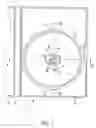
BRIEF DESCRIPTION OF THE DRAWINGSFIG. 1 is a front view in the condition of having opened the optical disk storing case in accordance with the invention;
FIG. 2 is the A-A line sectional view of FIG. 1;
FIG. 3 is the B-B line sectional view of FIG. 1;
FIG. 4 is a bottom view in the condition of having opened the optical disk storing case of the invention;
FIG. 5 is a sectional view in the condition of having laid in order to contain an optical disk in a case;
FIG. 6 is a sectional view in the condition of having contained the optical disk;
FIG. 7 is a sectional view for explaining the condition of removing an optical disk.
DETAILED DESCRIPTION OF THE PREFERRED EMBODIMENTWith reference to FIGS. 1-4, an optical disc storing case in accordance with the present invention is shown and the detail structure is explained as follows:
An optical disc storing case 1 in accordance with this invention is a closing motion type case made from plastic and includes a right cover 1a and a left cover 1b, which are formed successively through a tooth-back plate 1c. The right cover 1a and the left cover 1b are respectively formed in the shape of a square box, and a crevice 7 is formed on a side of the right cover 1a for insertion of a finger, so as to allow the user to open the disc storing case conveniently.
Moreover, a pair of resilient tongue pieces 2 and 4 are arranged inside the optical disc storing case 1 in such a way that their extremity ends are confronted with each other. Protrusions 2a and 4a are arranged at each of the extremity ends and confronted with each other to form a column-like disk engaging means. Then, the resilient tongue pieces 2a and 4a are connected to the bottom surface of the right cover 1a by means of ribs 3a, 3b, 5a and 5b which are protruded at both sides of the resilient tongue pieces 2a and 4a. The ribs 3a, 3b, 5a and 5b act as supporting point of the resilient tongue pieces, so that when the extremity ends of the resilient tongue piece are pushed down, their rear ends will be sprung up. On the upper rim of the protrusions 2a and 4a are formed with protrusive swelling edge 2b and 4b. Furthermore, a ring-shaped protruding line 6 is integrally formed on the periphery section of the inner surface of the right cover 1a, which is used to support the periphery section of an optical disc. A couple of notches 8 and 8 are formed two upper and lower sides of the protruding line 6, via which, the user can lift up the optical disc with finger.
Referring to FIGS. 5-7, which explain how the optical disc is put into and taken out of the optical disc storing case 1 as follows:
When putting an optical disk 10 in the optical disc storing case 1, the user should align a feed-hole 10a of the optical disk 10 to the column-like disc engaging means formed by the protrusion 2a and 4a (as shown in FIG. 5) and then depresses the portion near the feed-hole 10a of the optical disk 10 with a finger. By this depression, the protrusive swelling edges 2b and 4b of the protrusions 2a and 4a of resilient tongue pieces 2 and 4 will be sprung up and pass through the feed-hole 10a and then to be locked with the surface of the optical disk 10 around the feed-hole 10a. At this moment, the protrusions 2a and 4a will be pushed by the elasticity of resilient tongue pieces 2 and 4 and closely abut against the inner circumference of feedhole 10a. Meanwhile, the periphery section of the optical disk 10 is supported by the ring-like protruding line 6. Through this way, the optical disk 10 is firmly positioned in the optical storing case 1 (as shown in FIG. 6).
When removing the optical disk 10 from the optical storing case 1, the user can depress the protrusions 2a and 4a of the resilient tongue pieces 2 and 4 from the top (the direction of arrow-head A of FIG. 7) so as to make the protrusion 2a and 4a approach mutually. At this moment, an outer diameter of cylinder protrusion of the combination of the protrusions 2a and 4a is reduced, which accordingly leads to a disengagement of the protrusions 2a and 4a from the feedhole 10a of the optical disc 10. As mentioned above that the ribs 3a, 3b, 5a and 5b are used as supporting point, thus the opposite end section of the resilient tongue pieces 2 and 4 will raise up respectively if protrusions 2a and 4a are pushed downward by the user, and synchronously a side the optical disk 10 will be pushed upwards by the opposite end section of the resilient tongue pieces 2 and 4 (the direction of arrow-head B of FIG. 7). Since the protrusions 2a and 4a disengaged from the feed-hole 10a and the optical disk 10 are raised upward by the opposite end section of the resilient tongue pieces 2 and 4 (refer to FIG. 7), the user is able to take the optical disc 10 out easily by inserting fingertip into the above-mentioned notches 8 and 8 on ring-like protruding line 6.
While we have shown and described various embodiments in accordance with the present invention, it should be clear to those skilled in the art that further embodiments may be made without departing from the scope of the present invention.
Claims
1. An optical disc storing case comprising: a left cover and a right cover, both of which successively connected to each other via a connecting member, a pair of resilient tongue pieces respectively arranged in the optical disc storing case in such a manner that their extremity ends are confronted with each other, wherein:
plural protrusions are arranged at the respective extremity ends of the resilient tongue pieces and confronted with each other to form a column-like disk engaging means, the resilient tongue pieces are connected to a bottom surface of the right cover by means of plural ribs that are protruded at both sides of the resilient tongue pieces, the ribs act as supporting point of the resilient tongue pieces.
2. The case for optical disk receipt according to claim 1, a ring-shaped protruding line is integrally formed on periphery section of the inner surface of the right cover, which is used to support periphery section of an optical disc.
Images & Drawings included:


Sources:
- United States Patent and Trademark Office - verify current appl. status at the USPTO↗
Similar patent applications:
- » 20100258461
CASES FOR STORING AN OPTICAL DISC
Recent applications in this class:
- » 20140262872 2014-09-18
DISK RETAINING PACKAGE - » 20120292210 2012-11-22
Method and Device for Storing and Retrieving a Disk - » 20120261280 2012-10-18
Memory Box - » 20120247988 2012-10-04
Merchandise Storage Container - » 20120193253 2012-08-02
Compact disk (CD) jewel case hinge storage apparatus and marketing method - » 20120044628 2012-02-23
CONTAINER LOCKING MECHANISM - » 20120042328 2012-02-16
Tray with a fitting convex portion - » 20120000802 2012-01-05
One-hand operable data disc case - » 20110203951 2011-08-25
Compact disc storage and protective enclosure - » 20110198249 2011-08-18
Compact disk (CD) jewel case hinge storage apparatus and marketing method