System of simulating resistive loads
US20060044005A1
2006-03-02
11/204,568
2005-08-16
✅ Patent granted
US 7,112,988 B2
2006-09-26
-
-
Minh Nhut Tang | Tung X. Nguyen
2025-08-16
Abstract:
A system of simulating resistive loads adapted for testing working characteristics of power supplies includes a power supply (100), a linking apparatus (10) and a resistance loading apparatus (40). The power supply has a plurality of outputs (120). The linking apparatus is electrically connected to the outputs of the power supply. The resistive load apparatus is electrically connected to the linking apparatus. The resistive load apparatus includes a plurality of resistance matching selectors.
Assignee:
- HON HAI Precision Industry CO., LTD. 1,310 🇹🇼 Tu-Cheng City, Taiwan
- Hon Hai Precision Industry Co., Ltd. 71 🇹🇼 , Taiwan
Interested in similar patents?
Get notified when new applications in this technology area are published.
Classification:
G01R31/36 IPC
Arrangements for testing electric properties; Arrangements for locating electric faults; Arrangements for electrical testing characterised by what is being tested not provided for elsewhere Arrangements for testing, measuring or monitoring the electrical condition of accumulators or electric batteries, e.g. capacity or state of charge [SoC]
G01R31/40 » CPC main
Arrangements for testing electric properties; Arrangements for locating electric faults; Arrangements for electrical testing characterised by what is being tested not provided for elsewhere Testing power supplies
G01R31/2846 » CPC further
Arrangements for testing electric properties; Arrangements for locating electric faults; Arrangements for electrical testing characterised by what is being tested not provided for elsewhere; Testing of electronic circuits, e.g. by signal tracer; Specific tests of electronic circuits not provided for elsewhere; Fault-finding or characterising using hard- or software simulation or using knowledge-based systems, e.g. expert systems, artificial intelligence or interactive algorithms
Description
BACKGROUND OF THE INVENTION1. Field of the Invention
The present invention relates to systems of simulating resistive loads, and particularly to a system of simulating resistive loads for testing performance of power supplies.
2. General Background
Conventionally, most of electronic apparatuses are not equipped power supplies themselves on account of volumes and costs. The electronic apparatuses need outer power supplies to offer electrical energy. The power supplies can affect performance of the electronic apparatuses.
Currently, the power supplies have no same standard. Dissimilar electronic apparatuses have dissimilar power supplies. An improper use of a power supply to an electronic apparatus will likely damage the electronic apparatus. Power supplies must be tested before being used to electronic apparatuses. Resistances are always used to simulate loadings of electronic apparatuses.
What is needed is to provide a system of simulating resistive loads which conveniently tests performance of power supplies.
SUMMARYA system of simulating resistive loads adapted for testing working characteristics of power supplies includes a power supply, a linking apparatus and a resistance loading apparatus. The power supply has a plurality of outputs. The linking apparatus is electrically connected to the outputs of the power supply. The resistive load apparatus is electrically connected to the linking apparatus. The resistive load apparatus includes a plurality of resistance matching selectors.
Other objects, advantages and novel features of the invention will become more apparent from the following detailed description when taken in conjunction with the accompanying drawings, in which:
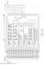
BRIEF DESCRIPTION OF THE DRAWINGSFIG. 1 is a block diagram of a system of simulating resistive loads in accordance with a preferred embodiment of the present invention;
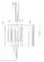
FIG. 2 is a circuit diagram of the system of simulating resistive loads of FIG. 1; and
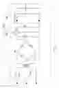
FIG. 3 is a circuit diagram of a heat dissipating apparatus of the system of simulating resistive loads of FIG. 1.
DETAILED DESCRIPTION OF THE EMBODIMENTReferring to FIG. 1, a system of simulating resistive loads in accordance with a preferred embodiment of the present invention is shown for testing performance of power supplies. The system of simulating resistive loads includes a power supply 100, a testing apparatus 200, and a detecting and displaying apparatus 400. The power supply 100 is electrically connected to the testing apparatus 200. The detecting and displaying apparatus 400 is also electrically connected to the testing apparatus 200.
The power supply 100 can be a switch power supply, an AC adaptor or a DC switch. The power supply 100 is a switch power supply in the preferred embodiment of the present invention.
Referring also to FIG. 2, the power supply 100 includes a plurality of outputs 120. The outputs 120 offer computer systems different voltages, such as +5Vdc, +12Vdc, −5Vdc, −12Vdc, +3.3Vdc, +5Vsbd, etc., as a character of the power supply 100.
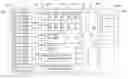
The testing apparatus 200 includes a linking apparatus 10, a resistive load apparatus 40 and a switch apparatus 80. The linking apparatus 10 is electrically connected all or parts of the outputs 120 of the power supply 100, and is electrically connected to the resistive load apparatus 40. The linking apparatus 10 includes a plurality of connectors 12. The resistive load apparatus 40 offers the power supply 100 correct resistive loads. The resistive load apparatus 40 includes a plurality of resistance matching selectors (50, 56, 60, 66, 70, 76). Each resistance matching selector includes a plurality of shunt-wound resistance units 52. Each resistance unit 52 includes a switch K and a resistance R. In the preferred embodiment, the resistive load apparatus 40 offers simulating resistive loads to +5Vdc, +12Vdc, −5Vdc, −12Vdc, +3.3Vdc, +5Vsbd, etc. The resistive load apparatus 40 includes six resistance matching selectors 50, 56, 60, 66, 70, 76 corresponding to the different six voltages +5Vdc, +12Vdc, −5Vdc, −12Vdc, +3.3Vdc, +5Vsbd. The resistance matching selectors 50, 56, 60, 66, 70, 76 have different amounts and parameters of the resistance units 52, as shown below:
| Voltages | Resistive loads | Currents | |
| +5 Vdc | 5 Ω | 1A | |
| 2.5 Ω | 2A | ||
| 1.25 Ω | 4A | ||
| 0.625 Ω | 8A | ||
| 0.3125 Ω | 16A | ||
| +12 Vdc | 12 Ω | 1A | |
| 6 Ω | 2A | ||
| 3 Ω | 4A | ||
| 1.5 Ω | 8A | ||
| −5 Vdc | 25 Ω | 0.2A | |
| 10 Ω | 0.5A | ||
| −12 Vdc | 60 Ω | 0.2A | |
| 24 Ω | 0.5A | ||
| +3.3 Vdc | 3.3 Ω | 1A | |
| 1.65 Ω | 2A | ||
| 0.83 Ω | 4A | ||
| 0.416 Ω | 8A | ||
| +5 Vsbd | 25 Ω | 0.2A | |
| 12.5 Ω | 0.4A | ||
| 6.25 Ω | 0.8A | ||
| 3.125 Ω | 1.6A | ||
A most current of the resistive load apparatus 40 is 31 ampere(A). 31A is large enough to satisfy all types of power supplies, so the resistive load apparatus 40 is likely suit all types of power supplies.
The switch apparatus 80 electrically connected to the resistive load apparatus 40 is to transform signals from the resistive load apparatus 40 to the detecting and displaying apparatus 400. The switch apparatus 80 is a switch-type electric component. In the preferred embodiment, the switch apparatus 80 is a multiway switch. The switch apparatus 80 includes a plurality of multiway connectors and an option connector 82. The multiway connectors are electrically connected with the corresponding resistance matching selectors 50, 56, 60, 66, 70, 76, respectively. The option connector 82 is electrically connected with the detecting and displaying apparatus 400.
The detecting and displaying apparatus 400 is used to detect and display parameters of voltages, currents and power of the power supply 100. The detecting and displaying apparatus 400 includes an instrument 420 displaying detecting results. The instrument 420 can be a multimeter or an oscillograph, etc. The instrument 420 includes two conductive wires. One of the conductive wires is connected with the option connector 82 of the switch apparatus 80. The other one of the conductive wires is grounded.
In working, a correct resistance load of the resistance loading apparatus is selected. The correct resistance load is equal to a resistance of an electric apparatus (not shown) that will use the power supply 100. For example, some types of power supplies having an output voltage of +5Vdc have a most current 20A. The resistance matching selector 50 of +5Vdc is selected. Resistance units 52 of 4A and 16A are selected and the corresponding switches Ks are turned on. The option connector 82 of the switch apparatus 80 is connected to the corresponding resistance matching selector 50. The detecting and displaying apparatus 400 tests working characteristics of the 20A and identifies whether the 20A satisfies the electric apparatus.
Referring also to FIG. 3, the testing apparatus 200 inevitably produces a lot of heat. Thus, a heat dissipating apparatus 300 is connected to the testing apparatus 200. The heat dissipating apparatus 300 includes an alternating current commutating part 320 and a heat dissipating part 360. The alternating current commutating part 320 converts +220Vac to +12Vdc. +12Vdc is offered to the heat dissipating part 360 after being filtered by capacitances C1 and C2. The heat dissipating part 360 includes two fans FAN1 and FAN2.
It is believed that the present invention and its advantages will be understood from the foregoing description, and it will be apparent that various changes may be made thereto without departing from the spirit and scope of the invention or sacrificing all of its material advantages, the examples hereinbefore described merely being preferred or exemplary embodiments of the invention.
Claims
What is claimed is:1. A system of simulating resistive loads adapted for testing working characteristics of power supplies, the system of simulating resistive loads comprising:
a power supply having at least an output;
a linking apparatus electrically connected to said output of the power supply; and
a resistive load apparatus electrically connected to the linking apparatus, the resistive load apparatus comprising at least one resistance matching selector.
2. The system of simulating resistive loads as claimed in claim 1, wherein the power supply comprises a plurality of outputs, the linking apparatus comprises a plurality of connectors electrically connecting to the outputs, respectively.
3. The system of simulating resistive loads as claimed in claim 2, wherein the resistive load apparatus comprises a plurality of resistance matching selectors connected to the connectors, respectively.
4. The system of simulating resistive loads as claimed in claim 3, wherein each of the resistance matching selectors comprises a plurality of shunt-wound resistance units, each of the resistance units comprises a switch in series with a resistance, the switch is electrically connected to the linking apparatus, the resistance is grounded.
5. The system of simulating resistive loads as claimed in claim 4, further comprising a detecting and displaying apparatus being used to detect and display parameters of voltages, current, and power of the power supply.
6. The system of simulating resistive loads as claimed in claim 5, further comprising a switch apparatus, wherein the switch apparatus is a multiway switch comprising a plurality of multiway connectors and an option connector, the multiway connectors are electrically connected with the corresponding resistances matching selectors respectively, the option connector is electrically connected with the detecting and displaying apparatus.
7. The system of simulating resistive loads as claimed in claim 6, wherein the detecting and displaying apparatus comprises an instrument displaying the parameters, the instrument includes two conductive wires, one of the conductive wires is electrically connected to the option connector, the other one of the conductive wires is grounded.
8. A system of simulating resistive loads adapted for testing working characteristics of power supplies, the system of simulating resistive loads comprising:
a power supply having a plurality of outputs; and
a testing apparatus, comprising:
a linking apparatus comprising a plurality of connectors electrically connected to the outputs, respectively; and
a resistive load apparatus comprising a plurality of resistance matching selectors electrically connected to the connectors respectively.
9. The system of simulating resistive loads as claimed in claim 8, wherein each of the resistance matching selectors comprises a plurality of shunt-wound resistance units, each of the resistance units comprises a switch in series with a resistance, the switch is electrically connected to a corresponding connector of the linking apparatus, the resistance is grounded.
10. The system of simulating resistive loads as claimed in claim 9, further comprising a detecting and displaying apparatus being used to detect and display parameters of voltages, current, and power of the power supply.
11. The system of simulating resistive loads as claimed in claim 10, further comprising a switch apparatus, wherein the switch apparatus is a multiway switch comprising a plurality of multiway connectors and a option connector, the multiway connectors are electrically connected with the corresponding resistances matching selectors respectively, the option connector is electrically connected with the detecting and displaying apparatus.
12. The system of simulating resistive loads as claimed in claim 11, wherein the detecting and displaying apparatus comprises an instrument displaying the parameters, the instrument includes two conductive wires, one of the conductive wires is electrically connected to the option connector, the other one of the conductive wires is grounded.
13. The system of simulating resistive loads as claimed in claim 8, wherein a heat dissipating apparatus is connected to the testing apparatus.
14. A method for testing a power supply, comprising the steps of:
preparing at least two resistance matching selectors each of which comprises at least one resistance unit capable of selectively simulating resistive loads for a power supply to be tested;
electrically connecting said at least two resistance matching selectors with said power supply respectively;
applying a selective one of said at least two resistance matching selectors onto said power supply based on a character of said power supply; and
verifying result signals from said selective one of said at least two resistance matching selectors.
15. The method as claimed in claim 14, wherein said at least one resistance unit comprises a switch and a resistance connected with said switch in series.
16. The method as claimed in claim 15, wherein an end of said switch other than connected with said resistance is electrically connected to said power supply, and an end of said resistance other than connected with said switch is grounded.
17. The method as claimed in claim 14, wherein a multiway switch is used to effectively apply said selective one of said at least two resistance matching selectors onto said power supply in said applying step.
18. The method as claimed in claim 14, further comprising the step of providing a heat dissipating apparatus for cooling said at least two resistance matching selectors.
Images & Drawings included:
Sources:
- United States Patent and Trademark Office - verify current appl. status at the USPTO↗
Recent applications in this class:
- » 20250290999 2025-09-18
METHODS AND APPARATUS TO DETECT AND DIAGNOSE FAULTS IN BUCK REGULATORS - » 20250290998 2025-09-18
METHOD FOR DETECTING INCORRECT INSTALLATION OF MEASUREMENT DEVICE AND ENERGY STORAGE SYSTEM USING THE SAME - » 20250283955 2025-09-11
ELECTRIC CIRCUIT HEALTH INDICATOR AND EFFICIENCY IMPROVEMENT DEVICE AND METHOD - » 20250277873 2025-09-04
Output Voltage Sense Protection Device and Method - » 20250277872 2025-09-04
CIRCUITS AND METHODS FOR SENSING CURRENT IN RESONANT TANKS OF SWITCHING POWER SUPPLIES - » 20250277871 2025-09-04
METHODS AND SYSTEMS FOR STATE OF HEALTH (SOH) MONITORING IN FUEL CELLS - » 20250271507 2025-08-28
REMAINING LIFETIME ESTIMATION METHOD FOR ELECTRONIC POWER CONVERTERS - » 20250264548 2025-08-21
SYSTEM AND METHOD FOR MATCHED-PORT POWER SUPPLY EVALUATION - » 20250258247 2025-08-14
DYNAMIC TIME WARPING (DTW)-BASED REAL-TIME DIAGNOSIS METHOD FOR COMMUTATION FAILURE (CF) OF PHASE-CONTROLLED CONVERTER - » 20250244406 2025-07-31
FAULT DETECTION IN AN ELECTRICAL POWER SYSTEM
Recent applications for this Assignee:
- » 20140363586 2014-12-11
Laser-based method for growing an array of carbon nanotubes - » 20140299819 2014-10-09
Method for making a carbon nanotube film - » 20140199855 2014-07-17
Method for making a carbon nanotube film - » 20110171419 2011-07-14
Electronic element having carbon nanotubes - » 20110110535 2011-05-12
Carbon nanotube speaker - » 20110036826 2011-02-17
Carbon nanotube heater-equipped electric oven - » 20110032196 2011-02-10
Touch panel and display device using the same - » 20110027486 2011-02-03
Method for preparing transmission electron microscope sample - » 20110024410 2011-02-03
Carbon nanotube heater - » 20110020563 2011-01-27
Carbon nanotube film composite structure, transmission electron microscope grid using the same, and method for making the same