Overlay mark for a non-critical layer of critical dimensions
US20060103034A1
2006-05-18
10/986,908
2004-11-15
Abstract:
An overlay mark for monitoring the critical dimension of a non-critical layer, comprising four first bars which are bar-shaped and separated from each other. The four first bars enclose to form a rectangle, and each first bar is correspondingly parallel to each side of the rectangle. The four second bars, wherein each second bar is bar-shaped and separated from each other, and the four second bars are positioned in the rectangle, and each second bar is correspondingly parallel to each side of the rectangle and comprise a plurality of third bars parallel with each other.
Interested in similar patents?
Get notified when new applications in this technology area are published.
Classification:
G03F7/70633 » CPC main
Photomechanical, e.g. photolithographic, production of textured or patterned surfaces, e.g. printing surfaces; Materials therefor, e.g. comprising photoresists; Apparatus specially adapted therefor; Exposure apparatus for microlithography; Information management, control, testing, and wafer monitoring, e.g. pattern monitoring; Wafer pattern monitoring, i.e. measuring printed patterns or the aerial image at the wafer plane Overlay
G03F9/7076 » CPC further
Registration or positioning of originals, masks, frames, photographic sheets or textured or patterned surfaces, e.g. automatically for microlithography; Alignment marks and their environment Mark details, e.g. phase grating mark, temporary mark
H01L22/12 » CPC further
Testing or measuring during manufacture or treatment; Reliability measurements, i.e. testing of parts without further processing to modify the parts as such; Structural arrangements therefor; Measuring as part of the manufacturing process for structural parameters, e.g. thickness, line width, refractive index, temperature, warp, bond strength, defects, optical inspection, electrical measurement of structural dimensions, metallurgic measurement of diffusions
H01L2223/5442 » CPC further
Details relating to semiconductor or other solid state devices covered by the group; Marks applied to semiconductor devices or parts comprising non digital, non alphanumeric information, e.g. symbols
H01L2223/54453 » CPC further
Details relating to semiconductor or other solid state devices covered by the group; Marks applied to semiconductor devices or parts for use prior to dicing
H01L2924/0002 » CPC further
Indexing scheme for arrangements or methods for connecting or disconnecting semiconductor or solid-state bodies as covered by; Technical content checked by a classifier Not covered by any one of groups , and
H01L2924/00 » CPC further
Indexing scheme for arrangements or methods for connecting or disconnecting semiconductor or solid-state bodies as covered by
H01L23/544 » CPC further
Details of semiconductor or other solid state devices Marks applied to semiconductor devices , e.g. registration marks,
Description
BACKGROUND OF THE INVENTION1. Field of the Invention
The present invention relates to an overlay mark, in particular, to an overlay mark for monitoring the critical dimensions of a non-critical layer.
2. Description of the Prior Art
As the dimension of the semiconductor becomes smaller, and with higher levels of integration, fabrication processes become more complicated and more difficult. Thus, the direction of semiconductor manufacturers has turned to monitoring and controlling, by employing real-time measuring devices, to respond or solve problems in real-time so as to lower damages caused by fabrication process errors.
Generally, other than controlling the critical dimensions of a wafer, the factor governing the success or failure of a wafer photolithography process is alignment accuracy. Thus, alignment accuracy measurement, or overlay error measurement, is an important task in the semiconductor fabrication process. An overlay mark is applied as a tool for measuring overlay error and is used to determine the alignment accuracy of the pattern of a photoresist layer after a photolithography process with that of a previous layer over the chip. In the process of monitoring alignment accuracy, a monitoring beam scans across the overlay. After scanning, signals representing the mean value of the position of the overlay are measured, compared, and the differences, i.e., overlay error, are calculated. If the overlay error is larger than the acceptable deviation value, this means that the alignment between the pattern of the photoresist layer and that of the chip has not reached the accuracy requirements, and a second photolithography process has to be repeated until the overlay error is smaller than the acceptable deviation value.
Although alignment accuracy can be monitored, the time and the cost used in fabrication process are increased.
SUMMARY OF THE INVENTIONThe present invention provides an overlay mark for monitoring the critical dimension of the non-critical layer, in which the monitoring time is reduced.
The present invention also provides an overlay mark for monitoring the critical dimension of the non-critical layer, in which the overlay mark comprises a plurality of bars for monitoring alignment accuracy readily.
To achieve the aforementioned objects, a preferred embodiment of the present invention provides an overlay mark for monitoring the critical dimension of the non-critical layer, comprising four first bars which are bar-shaped and separated from each other. The four first bars enclose to form a rectangle, and each first bar is correspondingly parallel to each side of the rectangle. Four second bars, wherein each second bar is bar-shaped and separated from each other, and the four second bars are positioned in a rectangle, and each second bar is correspondingly parallel to each side of the rectangle and comprise a plurality of third bars paralleled with each other.
These and other objectives of the present invention will become obvious to those of ordinary skill in the art after reading the following detailed description of the preferred embodiment.
It is to be understood that both the foregoing general description and the following detailed description are exemplary, and are intended to provide further explanation of the invention as claimed.
BRIEF DESCRIPTION OF THE DRAWINGSThe accompanying drawings are included to provide a further understanding of the invention, and are incorporated in and constitute a part of this specification. The drawings illustrate embodiments of the invention and, together with the description, serve to explain the principles of the invention. In the drawings,
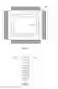
FIG. 1 is a top view of an overlay mark in accordance with a preferred embodiment of the present invention; and
FIG. 2 is a top view of a second bar in accordance with a preferred embodiment of the present invention.
DETAILED DESCRIPTION OF THE PREFERRED EMBODIMENTSThe present invention provides an overlay mark for monitoring the critical dimension of the non-critical layer, comprising four first bars which are all bar-shaped and separated from each other. The first bars enclose to form a rectangle. Each first bar is correspondingly parallel with each side of the rectangle. Four second bars, which are all bar-shaped and separated from each other, are positioned in the rectangle. Each second bar is correspondingly adjacent to each first bar and is composed of a plurality of third bars which are parallel with each other. Each third bar is vertically and correspondingly positioned.
FIG. 1 is a top view of an overlay mark in accordance with a preferred embodiment of the present invention. As shown in FIG. 1, the overlay mark comprises four first bars 10 and four second bars 12, which are all bar-shaped. Four first bars enclose to form a rectangle 14. Each first bar is separated from each other and is correspondingly parallel with each side of the rectangle 14. The first bars 10 represent the location of the fore-layer.
In addition, each of the four second bars 12 in the rectangle 14 is separated from each other and is correspondingly parallel with each side of the rectangle 14. That is, each second bar 12 is parallel and adjacent (but not close to) to the corresponding first bar 10. In this embodiment of the present invention, since four second bars are positioned in the rectangle 14, the length of the second bar 12 is shorter than the length of the first bar 10.
FIG. 2 is a top view of a second bar in accordance with a preferred embodiment of the present invention. In this embodiment of the present invention, each second bar is composed of a plurality of third bars 16, which are all bar-shaped and separated form each other. The third bars 16 are vertical correspondingly to the side of the rectangle 14, and vertical correspondingly to the first bars 10. It should be noted that the distances between the third bars 16 are not limited, and are designed depending on the requirement or designed by simulation in order to obtain the ideal values. One of the advantages of the present invention is that the third bars that are parallel and separated from each other are used for monitoring the critical dimension of the non-critical layer. The principle of monitoring of the present invention is by employing line-end shortening of the second bars 12 having the third bars 16 formed during defocus and employing the characteristic of non-influence by the defocus at the etched first bars. The third bars 16 cause a center shift as a result of the defocus during the measuring of alignment accuracy, and thus, by reverse calculation of the amount of center shift, a relative defocus is obtained. Based on this principle, monitoring the critical dimension of the non-critical layer can be obtained readily.
The embodiment above is only intended to illustrate the present invention; it does not, however, to limit the present invention to the specific embodiment. Accordingly, various modifications and changes may be made without departing from the spirit and scope of the present invention as described in the following claims.
Claims
What is claimed is:1. An overlay mark for monitoring critical dimension of a non-critical layer, comprising
four first bars, wherein each first bars is bar-shaped and separated from each other and the four first bars enclose to form a rectangle, and each first bar is correspondingly parallel to each side of the rectangle; and
four second bars, wherein each second bar is bar-shaped and separated from each other, and the four second bars are positioned in the rectangle, and each second bar is correspondingly parallel to each side of the rectangle and comprise a plurality of third bars parallel with each other.
2. The overlay mark for monitoring critical dimension of a non-critical layer of claim 1,
wherein each third bar is vertical to the corresponding side of the rectangle.
3. The overlay mark for monitoring critical dimension of a non-critical layer of claim 1,
wherein each third bar is separated from each other.
4. The overlay mark for monitoring critical dimension of a non-critical layer of claim 1,
wherein the length of each second bar is shorter than the length of an adjacent first bar.
5. An overlay mark for monitoring critical dimension of a non-critical layer, comprising
four first bars, wherein each first bar is bar-shaped and separated from each other and the four first bars enclose to form a rectangle, and each first bar is correspondingly parallel to each side of the rectangle; and
four second bars, wherein each second bar is bar-shaped and separated from each other, and the four second bars are positioned in the rectangle, and each second bar is correspondingly parallel to each side of the rectangle and comprise a plurality of third bars parallel with each other, and wherein each third bar is vertical to the corresponding side of the rectangle.
6. The overlay mark for monitoring critical dimension of a non-critical layer of claim 5,
wherein each third bar is separated from each other.
7. The overlay mark for monitoring critical dimension of a non-critical layer of claim 5,
wherein the length of each second bar is shorter than the length of an adjacent first bar.
Images & Drawings included:

Sources:
- United States Patent and Trademark Office - verify current appl. status at the USPTO↗
Recent applications in this class:
- » 20250172881 2025-05-29
CALIBRATED MEASUREMENT OF OVERLAY ERROR USING SMALL TARGETS - » 20250147430 2025-05-08
FREQUENCY-PICKED METHODOLOGY FOR DIFFRACTION-BASED OVERLAY MEASUREMENT - » 20250147429 2025-05-08
DETERMINING A MEASUREMENT RECIPE IN A METROLOGY METHOD - » 20250123570 2025-04-17
SEMICONDUCTOR STRUCTURE AND SYSTEM FOR MANUFACTURING THE SAME - » 20250123569 2025-04-17
USE OF ALTERNATING LAYER PATTERNS APPROACH FOR EFFECTIVE OVERLAY METROLOGY IN MULTI-STACK DIE APPLICATIONS - » 20250093786 2025-03-20
MULTI-COLUMN LARGE FIELD OF VIEW IMAGING PLATFORM - » 20250085642 2025-03-13
MEASUREMENT OPTICAL SYSTEM FOR METROLOGY INSPECTION AND METHOD OF MEASURING OVERLAY USING THE SAME - » 20250053096 2025-02-13
Flexible Measurement Models For Model Based Measurements Of Semiconductor Structures - » 20250044709 2025-02-06
METHOD AND APPARATUS TO DETERMINE OVERLAY - » 20250021019 2025-01-16
IMAGING OVERLAY TARGETS USING MOIRÉ ELEMENTS AND ROTATIONAL SYMMETRY ARRANGEMENTS