Wheel hub drive
US20060113853A1
2006-06-01
10/539,295
2003-12-16
✅ Patent granted
US 7,245,052 B2
2007-07-17
WO; PCT/EP03/14289; 20031216
WO; WO2004/058531; 20040715
Dang Le
2024-04-20
Abstract:
A wheel hub drive for a running wheel (10) is described. The drive having a transmission (7), a motor (8) and a brake (11), such that the enveloping circle (9) of the wheel hub drive is determined by the running wheel and the transmission (7), motor (8) and brake are located within a circle whose radius is determined by the running wheel (10).
Assignee:
- ZF FRIEDRICHSHAFEN AG 3,767 🇩🇪 Friedrichshafen, Germany
Interested in similar patents?
Get notified when new applications in this technology area are published.
Classification:
B60K7/0007 » CPC main
Disposition of motor in, or adjacent to, traction wheel the motor being electric
F16D55/02 » CPC further
Brakes with substantially-radial braking surfaces pressed together in axial direction, e.g. disc brakes with axially-movable discs or pads pressed against axially-located rotating members
B60K17/043 » CPC further
Arrangement or mounting of transmissions in vehicles characterised by arrangement, location, or kind of gearing Transmission unit disposed in on near the vehicle wheel, or between the differential gear unit and the wheel
B60K2007/0046 » CPC further
Disposition of motor in, or adjacent to, traction wheel the motor moving together with the vehicle body, i.e. moving independently from the wheel axle
B60K2007/0092 » CPC further
Disposition of motor in, or adjacent to, traction wheel the motor axle being coaxial to the wheel axle
B60K1/00 IPC
Arrangement or mounting of electrical propulsion units
B60K1/00 IPC
Arrangement or mounting of propulsion units in vehicles
H02K7/10 IPC
Arrangements for handling mechanical energy structurally associated with dynamo-electric machines, e.g. structural association with mechanical driving motors or auxiliary dynamo-electric machines Structural association with clutches, brakes, gears, pulleys or mechanical starters
H02K49/00 IPC
Dynamo-electric clutches; Dynamo-electric brakes
H02P15/00 IPC
Arrangements for controlling dynamo-electric brakes or clutches
H02K7/02 IPC
Arrangements for handling mechanical energy structurally associated with dynamo-electric machines, e.g. structural association with mechanical driving motors or auxiliary dynamo-electric machines Additional mass for increasing inertia, e.g. flywheels
Description
The present invention concerns a wheel hub drive according to the preamble of Claim 1.
In the prior art, wheel hub drives are usually used in floor trolleys. Since compared with flat or conical gear transmissions, they have the advantage that the transmission, drive motor, brake and wheel take up the least space. In addition, the use of wheel hub drives, enables chassis without through-going axle shafts to be made.
An essential feature of a wheel hub drive is the enveloping circle, i.e., the circle produced around the steering axis when the drive is steered or turned. In wheel hub drives of the prior art, the enveloping circle is determined by the dimensions of the transmission in combination with the motor and brake. This means that the radius of the enveloping circle is relatively large compared with the radius of a circle determined during steering by the turning of the running wheel.
The purpose of the present invention is to indicate a wheel hub drive in which the running wheel is what determines the enveloping circle, so that the smallest possible enveloping circle results.
This objective is achieved by the characteristics of Claim 1. Other design features and advantages emerge from the subordinate claims.
In the wheel hub drive, it is proposed to integrate a brake whose dimensions are very compact so that the enveloping circle of the wheel hub drive is determined by the running wheel, the transmission, motor and brake being arranged within a circle whose radius is determined by the running wheel.
According to the invention, the stator of the brake consists of a sheet component or sintered component bolted to the housing cover. In addition, the armature disk is also made from a sheet and connected to the stator with positive locking by way of balls. Moreover, the rotor also consists of a sheet that supports the brake lining and is fixed on the motor shaft by friction force.
The design and very simple structure provides an enveloping circle which is described by the running wheel. This is very advantageous for vehicles with wheel hub drives, since structural space is also made available for the necessary aggregates to be incorporated.
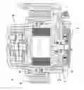
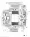
Below, a preferred example embodiment of the invention is described in more detail and illustrated schematically in the attached drawing.
As shown in the figure, the wheel hub drive according to the invention comprises a brake 11, whose stator 1 preferably consists of a sheet or sintered component bolted to the housing cover 12. In this embodiment the stator 1 is connected by positive locking via balls 3 to an armature disk made from sheet. Further, the brake 11 comprises a rotor 4 preferably made from sheet, which supports the brake lining 5 and is fixed on the motor shaft 6 by friction force. If no large braking torques are needed, the wheel hub drive can also be made without a brake lining 5.
The very compact structure shown here enables the transmission 7 and motor 8 (in a plan view of the wheel hub drive according to the figure) to be located within a circle radius which is determined by the running wheel 10, so that the enveloping circle 9 of the wheel hub drive according to the invention is determined by the running wheel 10.
REFERENCE NUMERALS
- 1 stator
- 2 armature disk
- 3 ball
- 4 rotor
- 5 brake lining
- 6 motor shaft
- 7 transmission
- 8 motor
- 9 enveloping circle
- 10 running wheel
- 11 brake
- 12 housing cover
Claims
1-7. (canceled)
8. A wheel hub drive for a running wheel (10), the wheel hub drive comprising a transmission (7), a motor (8) with a motor shaft (6) and a brake (11) with a stator (1), an armature disk (2) and a rotor (4), the motor (8) being arranged between the brake (11) and the transmission (7), the transmission is made as a planetary transmission and the armature disk (2) is connected by balls (3) to the stator (1) with positive locking so that forces can be transmitted in a radial direction, the rotor (4) being fixed on the motor shaft (6), so that an enveloping circle (9) of the wheel hub drive is determined by the running wheel (10) in such manner that the radius of the enveloping circle is approximately the same as the radius of the running wheel.
9. The wheel hub drive for a running wheel (10) according to claim 8, wherein the stator (1) comprises one of a sheet and a sintered component.
10. The wheel hub drive for a running wheel (10) according to claim 8, wherein the stator (1) is bolted to a housing cover (12).
11. The wheel hub drive for a running wheel (10) according to claim 8, wherein the armature disk (2) comprises a sheet.
12. The wheel hub drive for a running wheel (10) according to claim 8, wherein the rotor (4) comprises a sheet.
13. The wheel hub drive for a running wheel (10) according to claim 8, wherein the rotor (4) is fixed to the motor shaft (6) by friction.
14. The wheel hub drive for a running wheel (10) according to claim 8, wherein the rotor (4) supports a brake lining (5).
Images & Drawings included:
Sources:
- United States Patent and Trademark Office - verify current appl. status at the USPTO↗
Similar patent applications:
- » 20230242209
STATOR RING-INTERNAL GEAR ASSEMBLY FOR A TRANSMISSION DEVICE OF A WHEEL HUB DRIVE COMPRISING A PLANETARY GEAR, WHEEL HUB DRIVE HAVING SUCH A STATOR RING-INTERNAL GEAR ASSEMBLY AND A VEHICLE OPERATED BY WHEEL HUB DRIVE AND MUSCLE POWER - » 20230242213
PLANET CARRIER RING-FREEWHEEL ASSEMBLY FOR A TRANSMISSION DEVICE OF A WHEEL HUB DRIVE COMPRISING AT LEAST ONE PLANETARY GEAR, WHEEL HUB DRIVE HAVING SUCH A PLANET CARRIER RING-FREEWHEEL ASSEMBLY AND A VEHICLE OPERATED BY WHEEL HUB DRIVE AND MUSCLE POWER - » 20230242214
Planet carrier ring sun gear assembly for a transmission device of a wheel hub drive comprising at least two planetary gears, wheel hub drive having such a planet carrier ring sun gear assembly and a vehicle operated by wheel hub drive and muscle power - » 20130049549
Electric wheel hub drive for a vehicle, in particular a bicycle, including a stator with an ironless hollow cylindrical stator winding - » 20060158024
Electrically-powered axle with wheel hub drive - » 20080302218
FOUR WHEEL DRIVE HUB LOCK REMOVAL TOOL - » 20140246893
Multi-speed hub drive wheels - » 20070267234
Wheel hub drive for industrial trucks - » 20120248849
WHEEL HUB DRIVE UNIT - » 20130012350
WHEEL HUB DRIVE FOR MOTOR VEHICLES
Recent applications in this class:
- » 20250289302 2025-09-18
Power Train for a Motor Vehicle - » 20250269712 2025-08-28
ELECTRIC AXLE ASSEMBLY - » 20250269711 2025-08-28
ELECTRIC AXLE ASSEMBLY - » 20250256561 2025-08-14
Modular systems for electric wheel assemblies - » 20250214411 2025-07-03
IN-WHEEL DRIVE ASSEMBLY - » 20250196616 2025-06-19
MODULAR AND INTEGRATED ELECTRIC VEHICLE DRIVING AND STEERING SYSTEM - » 20250196615 2025-06-19
DRIVING MODULE FOR VEHICLE AND POWER SUPPLY STRUCTURE - » 20250196614 2025-06-19
WHEEL ASSEMBLY AND A VEHICLE INCLUDING THE SAME - » 20250196613 2025-06-19
AXLE ASSEMBLY HAVING AN ELECTRIC MOTOR - » 20250196612 2025-06-19
MOTOR SYSTEM WITH STATOR WINDINGS CONNECTED TO MULTIPLE DRIVES
Recent applications for this Assignee:
- » 20250293169 2025-09-18
STACKABLE POWER SEMICONDUCTOR MODULE - » 20250292970 2025-09-18
CAPACITIVE WINDING OF A DC LINK CAPACITOR AND DC LINK CAPACITOR WITH A COMMON-MODE CURRENT LEAKAGE FUNCTION - » 20250286013 2025-09-11
APPARATUS AND METHOD FOR MANUFACTURING A POWER SEMICONDUCTOR DEVICE - » 20250283529 2025-09-11
DRIVE UNIT FOR A VEHICLE - » 20250282215 2025-09-11
MOTOR VEHICLE TRANSMISSION FOR AN AT LEAST PARTIALLY ELECTRICALLY DRIVEN MOTOR VEHICLE - » 20250282209 2025-09-11
DRIVE UNIT FOR A VEHICLE - » 20250269709 2025-08-28
ARTICULATED RIGID AXLE OF A VEHICLE WITH AN AXLE SUPPORT WITH AN ELECTRIC MACHINE AS DRIVE - » 20250262892 2025-08-21
AXLE SUPPORT SYSTEM FOR A VEHICLE AXLE - » 20250256806 2025-08-14
BATTERY TERMINAL FOR TWO-WHEELED VEHICLES HAVING AN ELECTRIC DRIVE UNIT - » 20250251033 2025-08-07
GEARBOX AND DRIVE UNIT WITH SUCH A GEARBOX