Fluid change system
US20060185757A1
2006-08-24
11/065,006
2005-02-24
Abstract:
A fluid change apparatus consisting of two components. One component is associated with the engine and the other component is associated with a source of new fluid and a receptacle for old fluid. The present invention provides a fast connection between the two components that completely compartmentalizes the fluids.
Interested in similar patents?
Get notified when new applications in this technology area are published.
Classification:
F01M11/0458 » CPC main
Component parts, details or accessories, not provided for in, or of interest apart from, groups - ; Filling or draining lubricant of or from machines or engines Lubricant filling and draining
B65B3/04 IPC
Packaging plastic material, semiliquids, liquids or mixed solids and liquids, in individual containers or receptacles, e.g. bags, sacks, boxes, cartons, cans, or jars Methods of, or means for, filling the material into the containers or receptacles
Description
BACKGROUND OF THE INVENTIONThe present invention is directed to a fluid change apparatus for removing used fluid from an engine and inserting new fluid into the engine. In particular, the present invention is directed to a fluid change apparatus that removes used fluid from the engine and inserts new fluid into the engine while compartmentalizing the fluids and preventing contamination of the environment.
Oil change systems for engines are known in the art. However, most oil change systems are prone to contaminating the environment with used oil. This becomes a severe problem when a great deal of oil change activity occurs at a particular location, such as a car rental fleet facilities or an airline maintenance facility. Similar problems arise when changing other engine fluids such as transmission fluids and coolants. Portable oil change systems are also known, but are generally susceptible to the same problems.
In high-use facilities such as car rental fleet facilities and airline maintenance facilities, there is a need for a fast fluid change apparatus that contains all fluids without contaminating the environment. Such fluids may include, but are not limited to: engine oils, both synthetic and petroleum-based; hydraulic fluids; coolants; transmission oils; and differential oils.
The present invention meets this need by providing a fluid change apparatus consisting of two components. One component is associated with the engine and the other component is associated with a source of new fluid and a receptacle for old fluid. The present invention provides a fast connection between the two components that completely compartmentalizes the fluids.
SUMMARY OF THE INVENTIONThe present invention is a fluid change apparatus for removing used fluid from an engine and inserting new fluid into the engine, comprising a first portion adapted to be connected to the engine and a second portion mating with the first portion and adapted to be connected to a source of new fluid and to a receptacle for old fluid. The first portion is adapted to be connected to the engine by a first connection to remove old fluid from the engine and by a second connection to insert new fluid into the engine. The second portion is adapted to be connected to the receptacle for old fluid by a third connection to transfer old fluid to the receptacle and is adapted to be connected to the source of new fluid by a fourth connection to transfer new fluid from the source. The first connection is removably connected to the third connection and the second connection is removably connected to the fourth connection by mating the first portion with the second portion. A trigger is provided to activate a mechanism for mating the first and second portions. Either the first portion or the second portion may be mobile or stationary.
The invention also includes a spring-loaded trigger within the second portion for making and breaking a connection between the source of new fluid and the new fluid port and simultaneously making a connection between the old fluid drain port and the old fluid receptacle. Separate pumps may be provided for new fluid and old fluid.
A principal object and advantage of the present invention is that it completely compartmentalizes fluids, preventing contamination of the environment.
Another principal object and advantage of the present invention is that if provides a quick connect/disconnect between two components.
Another principal object and advantage of the present invention is that it provides a quick connect/disconnect for both old fluid removal and new fluid insertion.
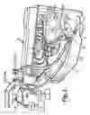
BRIEF DESCRIPTION OF DRAWINGSFIG. 1 is a perspective view of an embodiment of the present invention associated with an engine.
FIG. 2 is a detailed perspective view of the apparatus shown in FIG. 1.
FIG. 3 is a detailed perspective view of one component of the apparatus shown in FIG. 1.
FIG. 4 is a detailed perspective view of a second component of the apparatus shown in FIG. 1.
FIG. 5 is a detailed perspective view of another embodiment of one of the components of the present invention.
FIG. 6 is a perspective view of another embodiment of the apparatus of the present invention associated with a maintenance facility.
FIG. 7 is a perspective view of part of the apparatus of FIG. 2, with some structure cut away to show internal structure.
DETAILED DESCRIPTION OF THE PREFERRED EMBODIMENTThe fluid change apparatus of the present invention is generally shown in the Figures as reference numerals 10, 110, 210.
In one aspect (FIG. 1), the apparatus 10 comprises a first portion 12 adapted to be connected to an engine E and a second portion 14 mating with the first portion 12 and adapted to be connected to a source S of new fluid and to a receptacle R for old fluid.
Preferably, the first portion 12 is adapted to be connected to the engine by a first connection 16 to remove old fluid from the engine and by a second connection 18 to insert new fluid into the engine. Preferably, the first connection 16 and second connection 18 comprise hoses 20 and couplers 22.
Preferably, the second portion 14 is adapted to be connected to the receptacle R for old fluid by a third connection 24 to transfer old fluid to the receptacle R and is adapted to be connected to the source of new fluid S by a fourth connection 26 to transfer new fluid from the source S. Preferably, the third connection 24 and fourth connection 26 further comprise hoses and couplers.
Preferably, the first connection 16 is removably connected to the third connection 24 and the second connection 18 is removably connected to the fourth connection 26. Preferably, these connections are made when the second portion 14 mates with the first portion 12.
Preferably (FIG. 5 and 7), the second portion 14 further comprises a body 28, connectors 30 within the body 28 mating with connectors 32 on the first portion 12, and a mechanism 34 mating the second portion 14 with the first portion 12. Preferably, the apparatus 10 further comprises a trigger 36 activating the mechanism 34. Preferably, the trigger 36 is spring-loaded.
The first portion 12 may be stationary with the second portion 14 mobile. Alternatively, the first portion 12 may be mobile and the second portion 14 may be stationary.
In another aspect (FIG. 1), the apparatus 110 further comprises a first portion 112 connectable to the new fluid port N on an engine E and to the old fluid drain port O on the engine E by separate connections 113. The apparatus 110 further comprises a second portion 114 removably connectable to the first portion 112 and having connections to the source S of new fluid and to the receptable R for old fluid. Preferably, the apparatus 10 further comprises a mechanism 134 mating the first portion 112 with the second portion 114 and connecting the source S of new fluid to the new fluid port N on the engine E and also connecting the old fluid drain port O on the engine E. Preferably, the apparatus 112 further comprise a trigger 136 activating the mechanism 134. Preferably, the trigger 136 is spring-loaded. The first portion 112 may be stationary and the second portion 114 may be mobile. Alternatively, the first portion 112 may be movable while the second portion 114 may be fixed.
In a third aspect (FIG. 1), the apparatus 210 further comprises an engine-mounted first portion 212 connected to the new fluid port N and to the old fluid drain port O by separate connections. The apparatus 210 further comprises a first pump P1 pumping old fluid from the engine E to the old fluid receptacle and a second pump P2 pumping new fluid from the source S to new fluid port N. The apparatus further comprises a mobile second portion 214 connected to a source S of new fluid and to an old fluid receptacle R and being removably connectable to the first portion 212, thereby connecting the new fluid port N to the source S and connecting the old fluid drain port O to the receptacle R. The apparatus further comprises a spring-loaded trigger 236 within the second portion 214, the trigger 236 making and breaking a connection between the source S and the new fluid port N and simultaneously making a connection between the old fluid drain port O and the receptacle R.
Preferably, the second portion 214 is insertable into the first portion 212 and inserting the second portion 214 into the first portion 212 simultaneously connects the engine's old fluid drain port O to the receptacle R and connects the engine's new fluid port N to the source of new fluid.
Operation of the present invention is as follows.
In the case where the first portion is stationary, the first portion 12, 112, or 212 may be located at a central maintenance facility where the source S of new fluid and the receptacle R for old fluid are co-located. Advantageously, the second, mobile portion 14, 114, or 214 may be mounted on a vehicle on which is also mounted a tank containing old fluid collected from various engines. The vehicle is brought into the central maintenance facility and the second, mobile portion 14, 114 or 214 is connected to the first portion 12, 112, or 212 as previously described. Old fluid from the tank on the vehicle is then transferred to the receptacle R, and another tank on the vehicle is replenished with new fluid from the source S. The vehicle may then be taken to another location where an engine is located, and the second, mobile portion 14, 114, 214 may be connected to another first portion 12, 112, 212 mounted, for example, on the engine, for draining old fluid and replenishing new fluid.
In another scenario, the first portion 12, 112, 212 is mobile and may be mounted on a boat, truck, car, aircraft, or other vehicle and be connected to the engine as previously described. The vehicle is brought to a maintenance facility where the second portion 14, 114, 214 is connected to the first portion 12, 112, 212 as previously described. Old fluid is then removed from the vehicle's engine and new fluid is inserted into the vehicle's engine as previously described.
Unless otherwise defined, all technical and scientific terms used herein have the same meaning as commonly understood by one of ordinary skill in the art to which this invention belongs. Although methods and materials similar to or equivalent to those described herein can be used in the practice or testing of the present invention, suitable methods and materials are described below. All publications, patent applications, patents, and other references mentioned herein are incorporated by reference in their entirety to the extent allowed by applicable law and regulations. In case of conflict, the present specification, including definitions, will control.
The present invention may be embodied in other specific forms without departing from the spirit or essential attributes thereof, and it is therefore desired that the present embodiment be considered in all respects as illustrative and not restrictive, reference being made to the appended claims rather than to the foregoing description to indicate the scope of the invention.
Claims
What is claimed:1. A fluid change apparatus for removing used fluid from an engine and inserting new fluid into the engine, comprising:
(a) a first portion adapted to be connected to the engine; and
(b) a second portion mating with the first portion and adapted to be connected to a source of new fluid and to a receptacle for old fluid.
2. The fluid change apparatus of claim 1, wherein the first portion is adapted to be connected to the engine by a first connection to remove old fluid from the engine and by a second connection to insert new fluid into the engine.
3. The apparatus of claim 2, wherein the second connection is a check valve
4. The apparatus of claim 2, wherein the first connection and second connection further comprise hoses and couplers.
5. The apparatus of claim 2, wherein the second portion is adapted to be connected to the receptacle for old fluid by a third connection to transfer old fluid to the receptacle and is adapted to be connected to the source of new fluid by a fourth connection to transfer new fluid from the source.
6. The apparatus of claim 4, wherein the first connection is removably connected to the third connection and wherein the second connection is removably connected to the fourth connection.
7. The apparatus of claim 5, wherein the removable connection between the first connection and third connection and between the second connection and fourth connection is made when the second portion mates with the first portion.
8. The apparatus of claim 4, wherein the third connection and fourth connection further comprise hoses and couplers.
9. The apparatus of claim 1, wherein the second portion further comprises a body, connectors within the body mating with the first portion, and a mechanism mating the second portion with the first portion.
10. The apparatus of claim 8, further comprising a trigger activating the mechanism.
11. The apparatus of claim 10, wherein the trigger is spring-loaded.
12. The apparatus of claim 1, wherein the first portion is stationary and the second portion is mobile.
13. The apparatus of claim 1, wherein the first portion is mobile and the second portion is stationary.
14. A fluid change apparatus for removing used fluid from an engine and inserting new fluid into the engine, the engine having a new fluid port and an old fluid drain port, the apparatus comprising:
(a) a first portion connectable to the new fluid port and to the old fluid drain port by separate connections;
(b) a second portion removably connectable to the first portion and having connections to a source of new fluid and to a receptacle for old fluid; and
(c) a mechanism mating the first portion to the second portion and connecting the source of new fluid to the new fluid port and connecting the old fluid drain port to the receptacle for old fluid.
15. The apparatus of claim 14, further comprising a trigger activating the mechanism.
16. The apparatus of claim 15, wherein the trigger is spring-loaded.
17. The apparatus of claim 14, wherein the first portion is stationary and the second portion is mobile.
18. The apparatus of claim 14, wherein the first portion is mobile and the second portion is stationary.
19. A fluid change apparatus for removing used fluid from an engine and inserting new fluid into the engine, the engine having a new fluid port and an old fluid drain port, comprising:
(a) an engine-mounted first portion connected to the new fluid port and to the old fluid drain port by separate connections;
(b) a second portion connected to a source of new fluid and to an old fluid receptacle and being removably connectable to the first portion, thereby connecting the new fluid port to the source of new fluid and connecting the old fluid drain port to the old fluid receptacle; and
(c) a spring-loaded trigger within the second portion making and breaking a connection between the source of new fluid and the new fluid port and simultaneously making a connection between the old fluid drain port and the old fluid receptacle.
20. The apparatus of claim 19, further comprising a first pump pumping old fluid from the engine to the old fluid receptacle and a second pump pumping new fluid from the source of new fluid to the engine.
21. The apparatus of claim 19, wherein the second portion is insertable into the first portion and wherein inserting the second portion into the first portion simultaneously connects the engine's old fluid drain port to the old fluid receptacle and connects the engine's new fluid port to the source of new fluid.
Images & Drawings included:


Sources:
- United States Patent and Trademark Office - verify current appl. status at the USPTO↗
Similar patent applications:
- » 20180340116
Phase change fracturing fluid system for phase change fracturing - » 20090192748
System for changing fluid temperature and method for controlling such a system - » 20160076998
Detection of chemical changes of system fluid via near infrared (NIR) spectroscopy - » 20240268696
DISTRIBUTED EXTRAVASATION DETECTION SYSTEM FOR FLUID CHANGE AND TO CONTROL THE FLUIDS LEVELS IN A BODY VIA WIRELESS INTERFACE BASED ON RATE OF ACTIVATION - » 20090075211
Immersion lithography fluid control system changing flow velocity of gas outlets based on motion of a surface - » 20060124534
Automatic transmission easy change fluid replacement system - » 20210177297
Distributed extravasation detection system for fluid change and to control the fluids levels in a body via wireless interface based on rate of activation - » 20070123770
System for detecting fluid changes and sensoring devices therefor - » 20140323969
Temperature changing intracorporeal fluid delivery system - » 20130274599
SYSTEMS FOR DETECTING FLUID CHANGES AND SENSOR DEVICES THEREFOR
Recent applications in this class:
- » 20250101894 2025-03-27
ENGINE-MOUNTED APPARATUS - » 20250059900 2025-02-20
AUTONOMOUS OIL CHANGE SYSTEM - » 20240344472 2024-10-17
OIL DRAINING SYSTEM - » 20230313717 2023-10-05
OIL DRAINING SYSTEM - » 20230279795 2023-09-07
Oil change cap and system - » 20220333514 2022-10-20
DOCKING STATION - » 20220307397 2022-09-29
Internal combustion engine and method of operating same - » 20220282648 2022-09-08
SYSTEM AND APPARATUS FOR PROCESSING FLUIDS PRESENT IN DEVICES HAVING HYDRAULIC SYSTEMS - » 20220243623 2022-08-04
Autonomous oil change system - » 20220120201 2022-04-21
Oil draining system