Drive circuit for a hair clipper
US20060207103A1
2006-09-21
11/376,168
2006-03-16
✅ Patent granted
US 7,446,495 B2
2008-11-04
-
-
Bentsu Ro | Thai Dinh
2027-07-06
Abstract:
A drive circuit for a hair clipper comprises an electric motor and a control circuit for operating the motor at a constant speed regardless of load conditions. The control circuit has detector means for sensing the supply voltage to the clipper and the clipper current, processor means for generating an error signal indicative of a change in supply voltage needed to maintain a constant motor speed and driver means responsive to the error signal for adjusting the supply voltage to the motor to maintain the speed constant.
Assignee:
- JOHNSON ELECTRIC S.A. 98 🇨🇭 La Chaux-de-Fonds, Switzerland
Interested in similar patents?
Get notified when new applications in this technology area are published.
Classification:
B26B19/388 » CPC main
Clippers or shavers operating with a plurality of cutting edges, e.g. hair clippers, dry shavers; Details of, or accessories for, hair clippers, or dry shavers, e.g. housings, casings, grips, guards; Electric features; Charging; Computing devices Sensors; Control
B26B19/06 » CPC further
Clippers or shavers operating with a plurality of cutting edges, e.g. hair clippers, dry shavers of the reciprocating-cutter type; Cutting heads therefor; Cutters therefor; Securing equipment thereof involving co-operating cutting elements both of which have shearing teeth
B26B19/02 IPC
Clippers or shavers operating with a plurality of cutting edges, e.g. hair clippers, dry shavers of the reciprocating-cutter type
H02P1/00 IPC
Arrangements for starting electric motors or dynamo-electric converters
Description
FIELD OF THE INVENTIONThis invention relates to a drive circuit for a hair clipper and to a hair clipper equipped with such a drive circuit.
PRIOR ARTKnown hair clippers usually comprise a fixed blade, a movable blade and a DC motor for reciprocating the movable blade relative to the fixed blade. If the supply voltage to the motor remains constant, the cutting speed of the hair clipper will decrease with an increase in load and this can cause damage to the hair and cause pain to a user. When the cutting speed slows, hair may be caught by the blades and pulled or torn.
AIM OF THE INVENTIONThe present invention seeks to overcome this drawback.
SUMMARY OF THE INVENTIONAccording to a first aspect of the present invention, there is provided a drive circuit for a hair clipper comprising an electric motor and a control circuit for operating the motor at a constant speed regardless of load conditions, the control circuit comprising detector means for sensing the supply voltage to the clipper and the clipper current, processor means for generating an error signal indicative of a change in supply voltage needed to maintain a constant motor speed and driver means responsive to the error signal for adjusting the supply voltage to the clipper to drive the motor at said constant speed.
Preferably, an error amplifier is provided for amplifying the error signal generated by the processor prior to supplying the signal to the driver means.
Preferably, the control circuit is an analog circuit or a digital circuit.
Preferably, the supply voltage to the clipper is regulated in linear mode or pulse width modulated switching mode.
According to a second aspect of the invention, there is provided a hair clipper equipped with a drive circuit according to the first aspect of the invention.
BRIEF DESCRIPTION OF THE FIGURESThe invention will now be more particularly described, by way of example, with reference to the accompanying drawings, in which:
FIG. 1 is a graph demonstrating the characteristics of a known hair clipper;
FIG. 2 is a graph demonstrating the relationship between a clipper's voltage and current at constant speed;
FIG. 3a is a schematic model of a clipper;
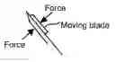
FIG. 3b is a schematic view showing a force applied to a moving blade of a hair clipper;
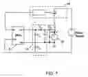
FIG. 4 is a schematic view of a drive circuit according to the first aspect of the present invention;
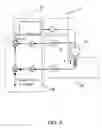
FIG. 5 is a circuit diagram of one specific embodiment of a drive circuit according to the first aspect of the present invention;
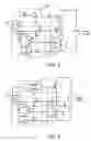
FIG. 6 is a circuit diagram of another specific embodiment of a drive circuit according to the first aspect of the present invention; and
FIG. 7 is a circuit diagram of yet another specific embodiment of a drive circuit according to the first aspect of the present invention.
DETAILED DESCRIPTION OF THE PREFERRED EMBODIMENTReferring firstly to FIG. 1 of the drawings, the speed-current characteristic of a hair clipper shown therein demonstrates that for a constant supply voltage clipping speed will decrease with increase in load current. This of course happens as the clipper penetrates the hair of a user and also depends upon the quantity of lubricant applied to the moving blade of the clipper. As stated previously, a reduction in clipping speed can cause damage to the hair and can cause pain to a user.
FIG. 2 demonstrates that it is possible to maintain a constant clipping speed by increasing the supply voltage to the clipper as the load on the clipper increases. Thus when the load current increases by ΔI as a result of a force applied to the clipper blades, the supply voltage to the clipper must be increased by ΔV in order to maintain a constant speed. It is to be noted that this has been found to be a linear relationship.
FIG. 3a is a schematic model of a clipper. The model is expressed by a voltage source 21 connected in series with a dynamic resistance 22. Therefore, the supply voltage to the clipper becomes:
V=ENL+Rd(I−INL), (1.1)
where
-
- V=Supply voltage to clipper,
- I=Clipper current,
- INL=No-load current to clipper
- ENL=No-load voltage of clipper,
- Rd=Dynamic resistance of clipper.
A no-load condition applies when there is no hair present between the clipper blades and there is sufficient lubricant to operate the blades of the clipper.
Experimentally, ENL and INL are simply measured at no-load condition at a predetermined clipping speed. As mentioned previously, if a force F is applied to the moving blade as shown in FIG. 3b, the clipper current increases by ΔI. However, the speed can be maintained by increasing the supply voltage to the clipper by ΔV.
By taking a partial differentiation of Equation (1.1) the dynamic resistance of the clipper can be expressed as:
Rd=ΔV/ΔI, (1.2)
where
-
- ΔV=Increase in V to maintain the clipper at no-load speed.
- ΔI=Increase in I subject to F applied
FIG. 4 shows a schematic view of a drive circuit for maintaining a constant motor speed regardless of load conditions.
A hair clipper is shown schematically by reference numeral 23. It comprises a fixed and a movable blade and a PMDC micromotor for reciprocating the movable blade relative to the fixed blade. The drive circuit for the clipper 23 comprises a signal detector 31 for sensing the supply voltage to the clipper and the clipper current, a processor 32 for generating an error signal, an error signal amplifier 33 and a motor driver 34. The error signal is representative of a change of supply voltage needed to maintain a constant motor speed.
The motor driver 34 is responsive to the error signal produced by the processor 32 and the error signal amplifier 33 and adjusts the supply voltage to the clipper to drive the clipper at a constant speed.
In the processor 32, the error signal is expressed by the following equation:
Error=VREF+K2I−K1 V (2.1)
Where
-
- VREF=Reference voltage defined by target speed,
- K1=Voltage coefficient,
- K2=Current coefficient,
- V=Controller's output voltage,
- I=Clipper current.
By continuously adjusting the motor driver 34, the processor 32 will make and keep the steady state of the error at zero. Therefore, Equation (2.1) can be written as follows V = 1 K 1 V REF + K 2 K 1 I ( 2.2 )
It is found that the controller's output V is proportional to VREF and I As compared with Equation (1.1), the parameters in Equation (2.2) are modelling the no-load clipper voltage and its dynamic resistance. That is,
V
REF
K
1
=
E
NL
-
R
d
I
NL
,
and
(
2.3
)
K
2
K
1
=
R
d
.
(
2.4
)
It is a simple matter to obtain the parameters of VREF/K1, and K2/K1 experimentally.
Therefore, by executing Equation (2.2) in real time, the controller is sensing the current value of I and giving a corrective action to V so that the clipping speed can be maintained constant.
Referring now to FIG. 5, the clipper voltage V is controlled by a power transistor Q2 working in linear mode. In this embodiment, the detector 31 comprises resistor R27, capacitor C1 and resistor R34. The processor 32 comprises resistors R25, R26, R32, R33, R28, and R29 and opamp (operational amplifier) U1. The error amplifier 33 comprises opamp U2 and capacitor C2. The motor driver 34 comprises resistors R23 and R31 and power transistors Q1, and Q2. This is an analog, low-cost circuit having no sophisticated ICs for process control and current sensing. There is also minimal EMI as the motor driver works in linear mode.
The circuit shown in FIG. 6 is similar to that shown in FIG. 5 except that the motor driver 34 operates in pulse width modulated (PWM) switching mode. Also, an anti-parallel diode 42 is provided across the clipper 23 to give a freewheeling path for the motor current.
For some high-end versions of the drive circuit, sophisticated features such as LCDs, tactile keypads, and battery-charger control will be provided. Thus, use of digital chips to realise the speed control becomes more versatile than the analog ones described with reference to FIGS. 5 and 6.
FIG. 7 shows a way of using a micro-controller unit (MCU) 51, which reads the clipper conditions from the detector 31 and executes Equation (2.2) to control the motor driver 34 operating in either linear or PWM switching mode.
It is therefore possible to provide a drive circuit for operating the clipper motor at constant speed regardless of load conditions. The drive circuit can be an analog or digital circuit and can regulate the clipper voltage in linear or PWM switching mode.
By maintaining a constant clipping speed regardless of load conditions, hair will not be damaged or squeezed by the moving blade. Users will therefore feel more comfortable during a hair cut. Secondly, the clipper can be designed to operate at a relatively low clipping speed to minimise acoustic noise. Thirdly, the quantity of lubricant applied to the clipper blades will not affect the clipping speed.
The embodiments described above are given by way of example only and various modifications will be apparent to persons skilled in the art without departing from the scope of the invention as defined by the appended claims.
Claims
1. A drive circuit for a hair clipper comprising an electric motor and a control circuit for operating the motor at a constant speed regardless of load conditions, the control circuit comprising detector means for sensing the supply voltage to the clipper and the clipper current, processor means for generating an error signal indicative of a change in supply voltage needed to maintain a constant motor speed and driver means responsive to the error signal for adjusting the supply voltage to the clipper to drive the motor at said constant speed.
2. The drive circuit of claim 1, wherein an error amplifier is provided for amplifying the error signal generated by the processor prior to supplying the signal to the driver means.
3. The drive circuit of claim 1, wherein the control circuit is an analog circuit.
4. The drive circuit of claim 1, wherein the control circuit is a digital circuit.
5. The drive circuit of claim 1, designed to regulate the supply voltage to the clipper in linear mode.
6. The drive circuit of claim 1, wherein the control circuit is designed to regulate the supply voltage to the clipper in pulse width modulated (PWM) switching mode.
7. A hair clipper equipped with the drive circuit of claim 1.
Images & Drawings included:


Sources:
- United States Patent and Trademark Office - verify current appl. status at the USPTO↗
Recent applications in this class:
- » 20250256415 2025-08-14
PERSONAL CARE DEVICE AND METHOD FOR DETERMINING A LOCATION OF THE PERSONAL CARE DEVICE ON A BODY PART - » 20250222607 2025-07-10
PROVIDING GUIDANCE TO A USER OF A PERSONAL CARE DEVICE - » 20250178224 2025-06-05
ELECTRIC GROOMING DEVICE - » 20250170735 2025-05-29
Integrated hair maintenance system and method of using the same - » 20250153376 2025-05-15
HEAT SENSOR ACTIVATED HAIR STYLING DEVICE - » 20250108530 2025-04-03
DEVICES AND METHODS FOR SMART PERSONAL GROOMING - » 20250108529 2025-04-03
HAIR CUTTING APPLIANCE AND ASSOCIATED POWER TRANSFORM MODULE - » 20240424700 2024-12-26
DETERMINING OPERATING PARAMETERS OF HAIR CUTTING DEVICES - » 20240351230 2024-10-24
ELECTRIC SHAVER - » 20240335965 2024-10-10
GRAY HAIR REMOVAL CUTTER, GRAY HAIR REMOVAL COMPONENT, GRAY HAIR REMOVAL COMB, AND GRAY HAIR REMOVAL SYSTEM
Recent applications for this Assignee:
- » 20120227531 2012-09-13
Telescopic tilting device - » 20110169367 2011-07-14
Stator of an electric motor - » 20110023798 2011-02-03
Electric motor - » 20100326378 2010-12-30
Electric motor - » 20100212628 2010-08-26
Throttle control module - » 20100183460 2010-07-22
Electric motor - » 20100181853 2010-07-22
PMDC motor - » 20100172015 2010-07-08
Electrophoretic display - » 20100156582 2010-06-24
Park lock solenoid - » 20100156235 2010-06-24
Electric motor