Insulation configuration suitable for crawl space installation
US20060236639A1
2006-10-26
11/101,798
2005-04-08
Abstract:
A packaged insulation product comprises an insulation assembly having first and second insulation blanket portions and a folded sheet facing sandwiched between the insulation blanket portions. Each insulation blanket portion has a major face bonded to the sheet of facing. The folded sheet of facing forms a hinge that connects the first and second insulation blanket portions. A wrapper may be used to at least partially enclose the insulation assembly, to form a packaged insulation product.
Interested in similar patents?
Get notified when new applications in this technology area are published.
Classification:
E04B9/001 » CPC main
Ceilings; Construction of ceilings, e.g. false ceilings; Ceiling construction with regard to insulation characterised by provisions for heat or sound insulation
E04B9/045 » CPC further
Ceilings; Construction of ceilings, e.g. false ceilings; Ceiling construction with regard to insulation comprising slabs, panels, sheets or the like being laminated
E04B1/00 IPC
Constructions in general; Structures which are not restricted either to walls, e.g. partitions, or floors or ceilings or roofs
E04G21/00 IPC
Preparing, conveying, or working-up building materials or building elements ; Other devices or measures for constructional work
Description
FIELD OF THE INVENTIONThe present invention relates to building products generally, and more specifically to insulation products.
BACKGROUNDInsulation products, such as fiber glass insulation, are widely accepted for commercial and residential buildings. The insulation products are made in a variety of configurations tailored to facilitate installation in specific locations.
Insulation typically is made and sold in widths that correspond to the most common spacings between joists or studs, between which the insulation is to be installed. In residential construction, the most common stud spacings are about 41 cm (16″) and about 61 cm (24″). However, in some crawl space cavities, the joists are spaced about 122 cm (48″) apart. For reasons of manufacturing and transportation economics, insulation is not typically sold in a 48″ width. Instead, two batts or lanes of insulation, each 24″ wide, are installed side by side to fill the 48″ wide space. This means that the outer longitudinal side edge of each batt or lane abuts a joist, and the interior longitudinal side edge of the two batts or lanes abut each other. The joists do not support the two interior longitudinal side edges.
The conventional method of installing batts side-by-side in a double-width crawl space typically involved supporting the batts from below with twine running across and/or diagonally to the joists, and fastening the twine to the joists. This process is awkward and time consuming, and increases installation costs.
CertainTeed Corp. of Valley Forge, Pa. has produced a double-lane product, including two separate, abutting, adjacent 11 inch lanes of insulation material, the abutting side edges of which are glued together to form a 22 inch lane of material that is more easily packaged and handled than an 11 inch product. A respective sheet of facing was adhered to each major face of each lane. This product was not, however, tailored for a double-width crawl space application. Essentially, to use this product in a crawl space with joists spaced 48″ apart, two adjacent 22 inch assemblies would be required, and there would still have been a 4″ gap.
U.S. Pat. No. 5,817,387 describes a modularized, encapsulated insulation assembly including a plurality of insulation modules which each include a compressible, resilient insulation material encapsulated within a vented, flexible envelope which overlays and encloses the major surfaces, lateral surfaces, and at least the end surfaces of the insulation material at the ends of insulation modules facing other modules of the assembly. Each adjacent pair of insulation modules is joined by a flexible connector strip which extends between adjacent ends of the insulation modules and lies either substantially in the plane of one of the major surfaces or about midway between the major surfaces of the insulation modules. The assembly is adapted to be installed in a wall cavity between studs. The insulation modules may differ in length and provide a location between the insulation modules where utilities can pass when the modularized, encapsulated insulation assembly is installed in a wall cavity.
An improved structure and method for insulation, suitable for crawl space use, is desired.
SUMMARY OF THE INVENTIONIn some embodiments, a method comprises providing a first insulation blanket portion adjacent to a second insulation blanket portion. A longitudinal direction of the first insulation blanket portion is aligned with a longitudinal direction of the second insulation blanket portion, and longitudinal edges of the first and second blanket portions face each other. A sheet of facing is bonded to a major face of the first insulation blanket portion and a major face of the second insulation blanket portion to form an assembly, so that a portion of the sheet of facing forms a hinge that connects the first and second insulation blanket portions. The assembly is folded about the hinge, with the folded sheet of facing sandwiched between the first and second insulation blanket portions.
In some embodiments, a method comprises providing an insulation assembly having first and second insulation blanket portions and a folded sheet of facing sandwiched therebetween. Each insulation blanket portion has a major face thereof bonded to the sheet of facing. A portion of the folded sheet of facing forms a hinge that connects the first and second insulation blanket portions. The insulation assembly is unfolded about the hinge, so that the first and second insulation blanket portions lie adjacent to each other, with longitudinal edges of the first and second blanket portions facing each other. The unfolded insulation assembly is installed between a pair of joists.
In some embodiments, a packaged insulation product comprises an insulation assembly having first and second insulation blanket portions and a folded sheet of facing sandwiched therebetween. Each insulation blanket portion has a major face thereof bonded to the sheet of facing. The folded sheet of facing forms a hinge that connects the first and second insulation blanket portions. A wrapper at least partially encloses the insulation assembly to form a packaged insulation product.
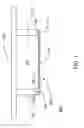
BRIEF DESCRIPTION OF THE DRAWINGSFIG. 1 is an end elevation view showing an embodiment of a faced insulation batt installed in a crawl space.
FIG. 2 is an end elevation view showing an embodiment of a double-width insulation product.
FIG. 3 is an end elevation view showing the product of FIG. 2 after folding the product about the facing thereof.
FIG. 4A shows the folded product of FIG. 3 after encapsulating the product in a packaging material.
FIG. 4B shows the folded product of FIG. 3 after partially wrapping the product in a packaging material.
FIG. 5 shows the product of FIG. 2 after insulation beneath a floor.
FIG. 6 shows a production conveyor carrying a plurality of sections of the product of FIG. 2 which have been cut from a continuous double-lane of product emerging from a production line.
FIG. 7 is a flow chart diagram shows a method for fabricating the product of FIGS. 2-6.
FIGS. 8-11 show a first method of folding the assembly of FIG. 2 on the fabrication line.
FIGS. 12-15 show a second method of folding the assembly of FIG. 2 on the fabrication line.
DETAILED DESCRIPTIONThis description of the exemplary embodiments is intended to be read in connection with the accompanying drawings, which are to be considered part of the entire written description. In the description, relative terms such as “lower,” “upper,” “horizontal,” “vertical,”, “above,” “below,” “up,” “down,” “top” and “bottom” as well as derivative thereof (e.g., “horizontally,” “downwardly,” “upwardly,” etc.) should be construed to refer to the orientation as then described or as shown in the drawing under discussion. These relative terms are for convenience of description and do not require that the apparatus be constructed or operated in a particular orientation. Terms concerning attachments, coupling and the like, such as “connected” and “interconnected,” refer to a relationship wherein structures are secured or attached to one another either directly or indirectly through intervening structures, as well as both movable or rigid attachments or relationships, unless expressly described otherwise.
FIG. 1 is a schematic diagram showing a first exemplary embodiment of a configuration 100 and method for installing a batt or lane of mineral fiber insulation 122 (e.g., fiber glass) between a pair of adjacent joists 112 beneath a floor 110. This configuration 100 may be used, for example, in a crawl space or basement. A dust reduction facing 124 to reduce dust from the insulation which may fall on the installer during installation, which may be a nonwoven mat, a woven fabric, or a perforated plastic film, is laminated to the bottom surface (in the orientation of FIG. 1) of the insulation layer 122, using an adhesive 126, such as a sprayed hot melt adhesive.
In some embodiments, the facing 124 provides a stapling tab 124t on each side of the batt 122. For example, if the insulation batt 122 is about 15″ (38 cm) to about 16″ (41 cm) wide, the facing 124 may be about 17″ (43 cm) to about 19″ (46 cm) wide, to provide a tab 124t of about one inch (2.5 cm) to about 1.5 inches (3.8 cm) width on each side of the batt 122. Similarly, if the insulation batt 122 is about 23″ (53 cm) to about 24″ (61 cm) wide, the facing 124 may be about 25″ (63 cm) to about 27″ (66 cm) wide, to provide a tab 124t of about one inch (2.5 cm) to about 1.5 inches (3.8 cm) width on each side of the batt 122.
In some embodiments, the adhesive 126 primarily comprises polypropylene, but other thermoplastic hot melt adhesives are also suitable. The adhesive 126 may be sprayed on the facing 124 at a temperature of about 350 degrees Fahrenheit. The facing 124 with the warm, tacky adhesive is then bonded to the top or bottom surface (bottom in FIG. 1) of the batt or lane 122 of mineral fiber insulation. Alternatively a water base adhesive may be used to bond the facing to the insulation. Also, the facing may include a heat activated adhesive layer or coating that can be activated (tackified) by the application of heat before the facing contacts the insulation. This may be achieved while the insulation 122 is traveling along an insulation production conveyor (not shown in FIG. 1). The facing is bonded to the top or bottom of the insulation on the conveyor, and the assembly is oriented with the facing on the bottom during installation, as shown in FIG. 1. Optionally, a vapor retarder facing (not shown in FIG. 1) may be laminated to the surface opposite the dust reduction facing 124.
The assembly 120, comprising a film/mineral fiber laminate is further processed on the manufacturing line by segmenting the product into batts or rolls, and the assembly 120 is subsequently packaged.
For installation under a floor in a crawl space or basement, the assembly 120 is positioned between a pair of adjacent joists 112, with the tabs 124t contacting the bottom surface of the joists. The tabs 124t can be easily fastened to respective joists 112 using staples 114, tacks or other fasteners.
FIGS. 2 to 5 show another embodiment, in which a double-width assembly 220 is provided for installation between joists that are, for example, about 81 cm (32″) or about 122 cm (48″) apart on centers.
As shown in FIG. 2, an assembly 220 comprises a first insulation blanket portion 222a adjacent to a second insulation blanket portion 222b. Each insulation blanket portion 222a and 222b has width WP, which is preferably a standard width, such as about 41 cm (16″) or about 61 cm (24″). A longitudinal direction (into the page in FIG. 2) of the first insulation blanket portion 222a is aligned with a longitudinal direction of the second insulation blanket portion 222b (as best seen in FIG. 6). In FIG. 2, Longitudinal edges or sides 222ea and 222eb of the first and second blanket portions 222a and 222b, respectively, face each other. The edges or sides 222ea and 222eb preferably contact each other in an abutting relationship, so that the first and second insulation blanket portions form a substantially continuous insulation blanket assembly having an assembly width WA that is substantially twice the blanket portion width WP. In other embodiments, there may be a small space between the edges 222ea and 222eb.
A sheet 224 of facing is bonded with adhesive 226 to a major face 223a of the first insulation blanket portion 222a and a major face 223b of the second insulation blanket portion 222b to form an assembly 220. Preferably, the sheet of facing 224 is formed of a material from a non-woven mat, a woven fabric, a perforated plastic film (e.g., a microporous film), a perforated metalized polypropylene or polyester film, a perforated foil/kraft paper laminate, a perforated foil/scrim/kraft (FSK) laminate, a perforated polypropylene/scrim/kraft (PSK) laminate, or an open net. Other materials such as a fire retarded kraft paper layer may be used, but the material for facing 224 should be strong enough to prevent accidental separation of the two insulation blanket portions 222a, 222b, flexible enough to be folded (as discussed below with reference to FIG. 3), and permeable enough to prevent moisture from becoming trapped in the insulation blanket portions 222a, 222b. If a perforated facing is used, an in-line perforating roller may be incorporated into the production apparatus, to form the perforations between the facing feed roll (not shown) and a station where the facing 224 is bonded to the insulation blanket portions 222a, 222b.
Alternatively, a continuous (non-perforated) plastic film may be used for environments where moisture entrapment is not a concern. In preferred embodiments, the facing 224 additionally performs a dust reduction function, but in other embodiments, the facing 224 may comprise an open net or open weave fabric that performs the mechanical support function without providing dust reduction. Such an open net or open weave fabric may be made from plastic.
In some embodiments, the tab portions 224t have grommets or a reinforcing layer (not shown) thereon, to prevent tearing of the tabs 224t while supporting the weight of the assembly 220 during and after installation.
The assembly 220 has a width WA that is substantially two times the width WP. For example, if the width WP is about 61 cm (24″), then the width WA is about 128 cm (48″). A portion 240 of the sheet of facing 224 acts as a hinge 240 that permanently connects the first and second insulation blanket portions 222a and 222b. If the facing 224 is perforated, then the facing may be located relative to the insulation blanket portions 222a and 222b so that none of the rows of perforations coincides with the hinge portion 240. A hinge portion 240 formed along a continuous (perforation free) portion of the facing 224 is slightly stronger and less likely to tear. However, so long as the perforations are relatively small and the facings are relatively strong, it isn't necessary to keep the perforations out of the hinge area.
In a preferred embodiment, the facing 224 extends beyond opposite longitudinal edges of the first and second insulation blanket portions 222a and 222b to form longitudinal fastening tabs 224t.
Optionally, an individual second facing 230a is bonded to a second major surface 225a of the first insulation blanket portion 222a, and an individual second facing 230b is bonded to a second major surface 225b of the second insulation blanket portion 222b.
FIG. 3 shows the assembly 220 of FIG. 2, after the assembly is folded about the hinge portion 240 of the facing 224. The insulation assembly 220 has first and second insulation blanket portions 222a, 222b arranged with a folded sheet of facing 224 sandwiched therebetween. Each insulation blanket portion 222a, 222b has a respective major face 223a, 223b bonded to the sheet of facing 224. The folded sheet of facing 224 forms a hinge 240 that connects the first and second insulation blanket portions 222a, 222b.
The assembly 220 has a width that is substantially the same as the blanket portion width WP. Although FIG. 2 shows the tabs 224t sticking straight out, this is only shown for ease of recognition. The tabs 224t can be folded flat against the side edges of the insulation blanket portions 222a and 222b for packaging the assembly 220, as best seen in FIGS. 4A and 4B.
FIG. 4A shows the folded insulation blanket assembly of FIG. 3, encased or encapsulated inside a packaging material 250, which may be paper or plastic, and may be a shrink wrap material, to form a packaged folded assembly 221. Although FIG. 4A only shows a single folded insulation blanket assembly encased within a package, any desired number of batts greater than one may also be encased in a single package for sale as a commercial unit. Within the packaging material 250, a plurality of packaged folded assemblies 221 may be placed one on top of another (with major faces abutting), or side-by-side, with side edges abutting.
FIG. 4B shows the folded insulation blanket assembly of FIG. 3, partially wrapped in a packaging material 251, which may be paper or plastic, and may be a shrink wrap material, to form a packaged folded assembly 219. Although FIG. 4B only shows a single folded insulation blanket assembly within a package, any desired number of batts greater than one may also be wrapped in a single package for sale as a commercial unit. The assemblies 219 may be placed one on top of another (with major faces abutting), or side-by-side, with side edges abutting.
FIG. 5 shows the assembly 220 of FIG. 2, installed beneath a floor 210 between joists 212, which are spaced a double-width apart, for example, about 32″ (81 cm) or about 48″ (122 cm). The tabs 224t are fastened to the joists 212 with fasteners such as staples 214, tacks or the like. The twine used to attach double-width insulation layers beneath floors in the prior are not required.
FIGS. 6 and 7 show an example of a process by which the products of FIGS. 2-5 are fabricated, packaged and installed.
FIG. 6 is a plan view showing a conveyor 260 on which many of the processing steps are performed. FIG. 6 shows three of the assemblies 220. In each assembly 220, the two insulation blanket portions 222a, 222b are shown side-by-side with their longitudinal edges abutting each other. The tabs 224t of the facing layer 224 are shown extending beyond the outer side edges of the insulation blanket portions 222a, 222b.
FIG. 7 is a flow chart diagram of an exemplary process.
At step 300, a first insulation blanket portion 222a is provided adjacent to a second insulation blanket portion 222b. A longitudinal direction of the first insulation blanket portion 222a (the direction of the conveyor 260 in FIG. 6) is aligned with a longitudinal direction of the second insulation blanket portion 222b. Longitudinal edges 222ea, 222eb of the first and second blanket portions 222a, 222b, respectively, face each other.
In some embodiments, each of the insulation blanket portions 222a, 222b is a continuous lane of mineral fiber insulation that is many times longer than the final cut product. The continuous lanes of mineral fiber insulation are received on the conveyor (shown in FIG. 6) that carries the insulation through the insulation production process. The insulation lanes are constructed from a low density fibrous glass or mineral wool or stone wool. The glass fibers may be formed by a rotary process, in which glass from a furnace (not shown) enters rotary spinners (not shown), where the glass is formed into long fibers in a loose glass wool, and the fibers are coated with a resin binder, such as phenol urea formaldehyde (PUFA), for example in a spraying process. The fibers are loaded onto a conveyor 260 and delivered to a curing oven (not shown). One of ordinary skill in the art understands that providing continuous lanes 222a, 222b on the same conveyor 260 on which the insulation blanket material is formed (at the output of the insulation production apparatus, not shown) provides a more efficient fabrication process than applying facing to individual batts after they are cut.
In other embodiments (not shown), each of the insulation blanket portions 222a, 222b is a previously cut batt having the same length as the final product.
At step 302, a sheet of facing 224 is bonded to a major face 223a of the first insulation blanket portion 222a and a major face 223b of the second insulation blanket portion 222b to form an assembly 220, so that a portion of the sheet of facing 224 forms a hinge 240 that connects the first and second insulation blanket portions.
The facing comprises a polymer film (a film can be perforated to make it water vapor permeable), a co extruded polymer film, a polymer film laminate, a nonwoven mat, a coated non-woven or woven material, a polymer film/nonwoven laminate, a woven polymer film, a woven polymer laminated to a solid polymer film, a polymer film/woven glass laminate, a bituminous coated paper or film, a reflective film or foil. Any of the foregoing film materials can be perforated to permit the passage of water vapor. Examples of materials suitable for the facing 224 include polyethylene film, aluminum or metallized foil, kraft paper, or the like. The facing can be water vapor permeable, or water vapor retardant (if the insulation is to be used in a location where moisture entrapment is not a concern). Potential facings include—thermally boded nonwoven polypropylene Fiberweb #FPN 319 supplied by BBA Fiberweb, Old Hickory, Tenn.; “REEMAY®” spunbond polyester nonwoven and “CELESTRA®38 spunbond polypropylene nonwoven, and “SPIRIT™” spunbond nylon 6.6 nonwoven manufactured by BBA Fiberweb Old Hickory, Tenn., perforated FB30 FSK and perforated VR900 PSK manufactured by Compac Coorporation of Hackettstown, N.J.; PGM 204 woven glass fabric manufactured by Saint-Gobain Technical Fabrics, Northboro, Mass.; PGM 255 polyester fiber nonwoven—woven polyester scrim laminate manufactured by Saint-Gobain Technical Fabrics; wet laid glass fiber and polyester fiber nonwoven manufactured by Lydall Corporation, Manchester, Conn.; R04035 “SODNET”, “R03015HAILNET,” and “BIRDNET” manufactured by Conwed Corporation, Minneapolis, Minn.; and a perforated metalized polyester or polypropylene film
Other examples of suitable facings include, but are not limited to: “FIRSTWRAP” Weather Barrier by Firstline Corporation of Valdosta, Ga.; “FORTIFIBER JUMBO TEX” from Fortifiber Corporation of Incline Village, Nev.; “TYVEK,” from DuPont of Wilmington Del.; “RUFCO-WRAP,” from Raven Industries of Sioux Falls, S Dak.; “TYPAR” house wrap from BBA FIBERWEB of Old Hickory, Tenn.; other nettings from Conwed including polypropylene nettings with an integral Ethylene Vinyl Acetate thermoplastic adhesive such as 750012-010 “THERMANET”® and R03436 “THERMANET®”; OB-5340 black polypropylene netting from InterNet Inc. of Minneapolis, Minn.; cross laminated polyethylene open mesh nonwoven fabric #SS1601 and #HS9342 UV resistant manufactured by Atlanta Nisseki CLAF Inc. of Kennesaw, Ga.; spunbond/meltblown/spunbond polypropylene nonwoven, and spundbond/film laminate such as Block-It (registered) NOAH (registered) manufactured by Kimberly-Clark Engineered Fabrics of Roswell, Ga.; metallized polypropylene film #MO11581 from Dunmore Corporation of Bristol, Pa.; PET-M metallized polyester film from Phoenix Films of Clearwater, Fla.
Exemplary woven glass fabrics may be a square pattern with 10×10 yarns per inch such as “PERMAGLAS-MESH” Resin Coated Fiber Glass Fabric 10×10, or “PERMAGLAS-MESH” Resin Coated Woven Glass Fabric 20×20, manufactured by Saint-Gobain Technical Fabrics of St. Catharines, Ontario, Canada.
There may optionally be a vapor retarder of a variable type (such as the “MEMBRAIN™” smart vapor retarder, sold by CertainTeed Corp. of Valley Forge, Pa.). A variable vapor retarder changes its permeability with the ambient humidity condition.
Table 1 lists three preferred vapor retarder—facing for embodiments with an ASTM E84 “Standard Test Method for Surface Burning Characteristics of Building Materials,”: maximum 25/50 flame spread/smoke developed classification. In Table 1, Vytech indicates VyTech Industries, Incorporated, Anderson, S.C.; Compac indicates Compac Corp. of Hackettstown, N.J., Fuller indicates HB Fuller Company of St. Paul, Minn.; Henkel indicates Henkel Corp., Elgin, Ill.
| TABLE 1 | ||||
| Mfg'r | Facing ID | Facing Type | Adhesive Mfg'r | Adhesive ID |
| Compac | VR900 | PSK | Fuller | V3484 |
| Vytech | Atlas 96 | Vinyl | Fuller | V3484 |
| Compac | FB30 | FSK | Henkel | 50-0965 |
Exemplary polymer film facings include: HDPE/PP co-extrusion, such as Tredegar 0.75 mil 275-77 blown HDPE/PP co-extrusion from Tredegar Film Products of Richmond, Va.; Apertured films from Tredegar Film Products of Richmond, Va.; Polyester film such as 142 gauge and 200 gauge film from SKC Inc. of Covington, Ga.; High Density Polyethylene film and Polypropylene film from Blueridge Films of McKenney, Va.; Polycarbonate film such as 3 mil GE Lexan FR83 from GE Polymershapes of Huntersville, N.C.; Ethylene Vinyl Alcohol film such as EVOH 44 and EVOH 29 from Soarus L.L.C. of Arlington Heights, Ill.; Bicor GBL film from ExxonMobil Films; Ethylene Vinyl Alcohol/Nylon film co-extrusion such as Capran Oxyshield OBS from Honeywell International of Pottsville, Pa.; YUPO Corporation FPG 80 and FPG 95 microporous synthetic paper polypropylene with inorganic fillers film from Yupo Corporation America of Chesapeake, Va.; Urethane film such as Deerfield Urethane 1 mil PS8010, Deerfield Urethane 1 mil PT1710-S, and Deerfield Urethane 1 mil PT9200-US from Deerfield Urethane, Inc of South Deerfield, Mass.: clear PVC film such as Grafix Plastics 3 mil clear lay rigid PVC from Grafix Plastics of Cleveland, Ohio; Saran film such as SC Johnson Premium Saran Film from SC Johnson of Racine, Wis.; co-extruded film of linear low density polyethylene with Saran resin such as Saranex 114, 115, and 116 and co-extruded film of low density polyethyene, Saran, and ethylene vinyl acetate such as Saranex 23E and 27E, and co-extruded low density polyethylene and Saran such as Saranex 14E from Dow Chemical of Midland, Mich.; Microporous breathable polypropylene film such as APTRA UV8 from RKW US, Inc. of Rome, Ga.; co-extruded film of ethylene vinyl acetate, polyethylene, and ethylene vinyl alcohol and co-extruded film of ethylene vinyl acetate, polyethylene, and nylon from Alcan Packaging of Neenah, Wis.; co-extruded film of nylon and ethylene vinyl acetate such as NNEHC303 from American Plastics Company, Inc. of Rhinelander, Wis.; and co-extruded film of low density polyethylene/ethylene vinyl acetate/low density polyethylene from Golden Eagle Extrusions of Milford, Ohio; and laminated film of nylon and polyethylene from Bradley's Plastic Bag Company of Downey, Calif.; and film produced from Exoxon Mobil of Baytown, Tex. ethylene vinyl acetate resins LD302.32, LD331.08, LD319.92, and LD713.93 In some embodiments, the adhesive 226 is applied to the facing 224. The adhesive 226 may be a hot melt adhesive, such as (but not limited to) polypropylene or polyethylene or ethylene vinyl acetate, but other thermoplastic or thermosetting adhesives may be used. In the case of thermosetting adhesives, the adhesive 226 and facing 224 may be applied before the insulation blanket material is passed through the curing oven. Other adhesives may include (but are not limited to) Henkel 80-8273 and “SANICARE®” HM-6700US thermoplastic hot melt adhesive; and Henkel 50-0965, 50-0965MHV, 50-0965, WB1961, 57-3027TT,and 56-7007UV water base adhesives from Henkel Corp., Elgin, Ill.; Thermoplastic Hot Melt, “COOLMELT”™ and “SPRAYPAC”™ 0452 from Loctite of Rocky Hill, Conn. Some thermoplastic adhesives such as Henkel “SANICARE®” HM-6700US are formulated to be applied at low temperatures compatible with lower melting polymer film substrates such as polyethylene.
The exemplary hot melt adhesive 226 may be sprayed on the facing 224 or on the surface of the insulation at a tank, hose, and gun temperature of about 350 degrees Fahrenheit. The temperature of the adhesive decreases before it hits the substrate. The facing 224 with the warm, tacky adhesive 226 is then bonded to the top or bottom surface (bottom in FIG. 1) of the lanes or batts 222a, 222b of mineral fiber insulation. In some embodiments, the facing 224 is a continuous lane and the bonding is performed on the mineral fiber insulation production conveyor (if the insulation material 222a, 222b is in the form of a continuous lane). One of ordinary skill in the art will understand that manufacturing efficiencies are achieved by bonding a continuous lane of facing 224 to two continuous lanes of insulation material 222a, 222b on the production conveyor at the output of the insulation production process.
In other embodiments, the adhesive comprises a film or thin sheet of a thermoplastic material that is positioned on the insulation blanket portions 222a, 222b, followed by the facing material. Then the method further comprises applying heat to activate a thermoplastic adhesive to bond the netting or facing to the fiber glass blanket.
In other embodiments, the facing 224 comprises a plurality of cut sheets (if the insulation material is in the form of pre-cut batts), and each facing sheet 224 is individually bonded to a pair of cut batts 222a, 222b.
At step 304, an optional individual second facing 230a may be bonded to a second major surface 225a of the first insulation blanket portion 222a using adhesive 232a, and an optional individual second facing 230b may be bonded to a second major surface 225b of the second insulation blanket portion 222b using adhesive 232b. In some embodiments, a vapor retarder facing is substituted for the second facings 230a, 230b and adhesive 232a, 232b. The second facing may be a vapor retarder material. The vapor retarder facing may be a 0.0005″ to 0.001″ thick high density polyethylene or polypropylene film; or a kraft paper coated with asphalt; or a non-perforated foil/kraft, FSK; or PSK laminate; ethylene vinyl acetate films; co-extruded films of polyethylene, ethylene vinyl acetate, and Saran; co-extruded films of nylon, ethylene vinyl acetate, and ethylene vinyl alcohol, and co-extruded film of ethylene vinyl acetate, ethylene vinyl alcohol, and an ionomer, and co-extruded film of nylon, ethylene vinyl alcohol, polyethylene, and polypropylene; co-extruded film of ethylene vinyl acetate, polyethylene, and ethylene vinyl alcohol; co-extruded film of ethylene vinyl acetate, polyethylene, and nylon, and laminations of polyethylene and nylon; or a 0.002″ thick nylon 6 film; or other polymer films that are vapor retarders of the variable type that change their water vapor permeability with the ambient humidity conditions. Such variable vapor retarders may include nylon films; ethylene vinyl alcohol films; coextruded film of nylon and ethylene vinyl alcohol. In some embodiments, the adhesive 232a, 232b is applied to the facings 230a, 230b, respectively, and then the facings are joined to the insulation blanket portions 222a, 222b.
The adhesive 232a, 232b may be a hot melt adhesive, such as (but not limited to) polypropylene, but other thermoplastic or thermosetting adhesives may be used. The adhesive 232a, 232b may be of the same type as the adhesive 226 used to bond the facing 224. The exemplary hot melt adhesive 232a, 232b may be sprayed on the facings 230a, 230b or on the surface of the insulation at a tank, hose, and gun temperature of about 350 degrees Fahrenheit. The temperature of the adhesive decreases before it hits the substrate. The facing 224 with the warm, tacky adhesive 226 is then bonded to the bottom or top surface (top in FIG. 1) of the lanes or batts 222a, 222b of mineral fiber insulation. In some embodiments, the second facings 230a, 230b are continuous lanes (if the insulation material 222a, 222b is in the form of a continuous lane). One of ordinary skill in the art will understand that manufacturing efficiencies are achieved by bonding continuous lanes of facing 230a, 230b to two continuous lanes of insulation material 222a, 222b on the production conveyor at the output of the insulation production process.
In other embodiments, the facings 230a, 230b are in the form of a plurality of cut sheets (if the insulation material is in the form of pre-cut batts 222a, 222b.)
At step 306, the assembly 220 is folded about the hinge 240, with the folded sheet of facing 224 sandwiched between the first and second insulation blanket portions 222a and 222b. In some embodiments, the folding step includes flipping the second insulation blanket portion 222b over on top of the first insulation blanket portion 222a using a lifting sled (not shown) while the assembly is on a production conveyor 260. Other means may be used for flipping one of the lanes 222b of insulation over onto the other lane 222a.
At step 308, in embodiments where the insulation blanket portions 222a, 222b are provided as continuous lanes on the insulation production conveyor 260, the folded assembly is cut along a transverse direction to form folded assembly segments 220. A typical segment length is 122 cm (48″), but the product can be cut in any desired length. A variety of inline cutting means may be used. For example, a blade (not shown) may be manually or automatically lowered periodically to sever each assembly 220 from the continuous product line. Alternatively, the cutting may be performed with a rotary die cutting cylinder (not shown) having at least one cutting rule, and an anvil cooperative with the rotary die cutting cylinder for severing the insulation assemblies 220. The rotary die cutting cylinder may be located along a path of the conveyor 260.
At step 310, the folded assemblies 220 are individually packaged. The packaging may completely encapsulate the assembly 220 (FIG. 4A) or the packaging may comprise a wrapper that only partially encloses the assembly 220 (FIG. 4B). In the case of a completely encapsulated assembly (FIG. 4A), the packaging material may be a shrink wrap material.
Steps 312 to 318 show a method of installing insulation. At step 312, a folded insulation assembly having first and second insulation blanket portions and a folded sheet of facing 224 sandwiched therebetween, is removed from a package 219 or 221. Each insulation blanket portion 222a, 222b has a major face thereof 223a, 223b, respectively, bonded to the sheet of facing 224. A portion of the folded sheet of facing 224 acts as a hinge 240 that connects the first and second insulation blanket portions 222a, 222b.
At step 314, the insulation assembly 220 is unfolded about the hinge 240, so that the first and second insulation blanket portions 222a, 222b lie adjacent to each other, with longitudinal edges 222ea and 222eb of the first and second blanket portions 222a and 222b facing each other.
At step 316, the unfolded insulation assembly 220 is installed between a pair of joists 212, which may support a floor 210. The installing step includes installing the assembly 220 with the facing 224 beneath the insulation blanket portions 222a, 222b, so that the facing 224 provides mechanical support to hold the insulation blanket portions 222a, 222b in place below the floor 210.
In embodiments where the sheet of facing 224 extends beyond the first and second insulation blanket portions 222a, 222b to form longitudinal tabs 224t along the length of the insulation assembly 220, the installing step includes fastening the longitudinal tabs 224t to the pair of adjacent joists 212. This may entail stapling or tacking the tabs 224t to the joists 212. If tabs 224t have any grommets, reinforcing strips, or other reinforcement (not shown), then the staples 214 or other fasteners are driven through the sections of the tabs 22t having such reinforcement.
FIGS. 8-11 show a method for folding the insulation assembly 220 inline at the end of an insulation production conveyor. FIG. 8 is an isometric view showing the double-width batt assembly 220 emerging from the production line on the conveyor 260. FIG. 8 shows the two batts (or continuous lanes) 222a and 222b side by side (held together with a common facing 224 on the bottom surface). In this portion of the process the conveyor 260 may be a roller conveyor or a belt conveyor.
FIG. 9 shows the use of a folding station 260f of the conveyor 260. Prior to the folding station 260f, the conveyor 260 has a width that is at least about WA, the width of the double-batt assembly 220. The section 260b of the conveyor 260 after the folding station 260f has a width of at least about WP, the width of a single batt or lane. The folding station 260f also includes a tapered section 260a, in which the width of the conveyor decreases from WA to WP. Preferably, the tapered section 260a is inclined upwards in the direction of motion. In a preferred embodiment, the folding process is initiated by running the two batts (or lanes) 222a, 222b up an inclined powered roller conveyor 260 that is at least as wide as the two lanes at the bottom and only as wide as one lane at the top. The lane 222a falls off the bottom conveyor as it narrows. To keep the upper batt (lane) 222b running up the conveyor 260, a tractor belt (not shown) that drags on the top surface of batt (lane) 222b runs at the same speed as lower conveyor 260 shown in FIG. 9 and a lower conveyer 270 (shown in FIG. 10) that carries the folded assembly 220 out of the folding station.
In FIG. 10, a powered roller conveyor 270 that is inclined and curved comes from the left at an incline at first under the batt (lane) 222a and then levels off under the batt (lane) 222a after the lane 222a has been pushed and twisted so that batt (lane) 222a is under the batt (lane) 222b at the leading edge of the batt (lane). The conveyor 260 carrying the batt (lane) 222b ends as the batt (lane) 222b is supported by the batt (lane) 222a and the conveyor 270 under the lane (batt) 222b.
FIG. 11 shows the batt (lane) 222b on top of the batt (lane) 222a with the folded facing 224 in between layers and being carried through the rest of the manufacturing process (chopping to batt lengths and packaging) by a flat roller or belt conveyor 270.
FIG. 12 shows an alternative conveying and “folding” sequence for a side by side batt, where the facing 224 has been laminated to the top surface of the insulation 222a, 222b in the production line. In FIG. 12, the production flow is from left to right. In FIG. 12, the two batts (or continuous lanes) 222a, 222b are side by side (held together with a common facing 224 on the top surface) on a conveyor 460. In this portion of the process the conveyor 460 can be a roller conveyor or a belt conveyor, for example.
In FIG. 13, the folding process is begun by using a twisted sled or ramp structure 470 (which may be made of metal) to bring the right lane from a horizontal position to an approximately vertical position. A tractor belt (not shown) runs at the same speed as the conveyer 460 and drags on the top of the horizontal lane 222a.
In FIG. 14, after the end of the twisting sled (ramp) 470, a powered or free-wheeling roller 480 mounted approximately over the hinged edge of the bottom batt (lane) 222a is used to push over the vertical left batt (lane) 222b so that batt (lane) 222b falls on top of the right lane 222a. The tractor conveyor positioned over lane 222a ends before lane 222b falls on top of lane 222a.
FIG. 15 shows the batt (lane) 222b on top of the batt (lane) 222a with the folded facing 224 in between the layers 222a, 222b. The folded assembly 220 is carried through the rest of the manufacturing process (chopping to batt lengths and packaging) by a flat roller or belt conveyor.
Although the invention has been described in terms of exemplary embodiments, it is not limited thereto. Rather, the appended claims should be construed broadly, to include other variants and embodiments of the invention, which may be made by those skilled in the art without departing from the scope and range of equivalents of the invention.
Claims
What is claimed is:1. A method, comprising the steps of:
providing a first insulation blanket portion adjacent to a second insulation blanket portion, a longitudinal direction of the first insulation blanket portion being substantially parallel with a longitudinal direction of the second insulation blanket portion, and longitudinal edges of the first and second blanket portions facing and abutting each other;
bonding a sheet of facing to a major face of the first insulation blanket portion and a major face of the second insulation blanket portion to form an assembly, so that a portion of the sheet of facing forms a longitudinal hinge that connects the first and second insulation blanket portions; and
folding the assembly about the hinge, with the folded sheet of facing sandwiched between the first and second insulation blanket portions.
2. The method of claim 1, further comprising:
cutting the folded assembly along a transverse direction to form folded assembly segments; and
packaging the folded assembly segments.
3. The method of claim 2, wherein:
each of the first and second insulation blanket portions has a blanket portion width,
the assembly has an assembly width prior to folding that is substantially twice the blanket portion width, and
the packaged folded assembly segments have a width approximately equal to the blanket portion width.
4. The method of claim 2, wherein the bonding, folding and cutting steps are performed on a production conveyor.
5. The method of claim 1, wherein:
each of the first and second insulation blanket portions has a blanket portion width, and
the first and second insulation blanket portions form a substantially continuous insulation blanket assembly prior to folding having an assembly width that is substantially twice the blanket portion width.
6. The method of claim 5, wherein the assembly width is about 122 cm (48 inches).
7. The method of claim 1, further comprising bonding an individual second facing to a second major surface of each of the first and second insulation blanket portions.
8. The method of claim 1, wherein the facing on the first major surface extends beyond opposite longitudinal edges of the first and second insulation blanket portions to form longitudinal fastening tabs.
9. The method of claim 1, wherein the folding step includes flipping the second insulation blanket portion over on top of the first insulation blanket portion while the assembly is on a production conveyor.
10. The method of claim 9, wherein the flipping step is performed using a ramp to twist the second insulation blanket portion with respect to the first insulation blanket portion.
11. The method of claim 1, wherein the sheet of facing is formed of a material from the group consisting of a non-woven mat, a woven fabric, a plastic film, a plastic netting, a perforated or non-perforated polypropylene/scrim/kraft (PSK) or foil/scrim/kraft (FSK) laminate, a plastic film laminated to a nonwoven or woven fabric.
12. The method of claim 11, wherein the plastic film is a microporous film.
13. The method of claim 11, wherein the method further comprises applying heat to activate a thermoplastic adhesive to bond the netting to the fiber glass blanket.
14. The method of claim 11, wherein the sheet of facing permanently connects the first and second insulation blanket portions.
15. The method of claim 11 where the plastic film is a variable type vapor retarder, and a water vapor permeability of the vapor retarder changes with ambient humidity conditions.
16. The method of claim 1, wherein the folding step includes:
moving the assembly with a first conveyor that has a tapered portion, the tapered portion allowing a first insulation blanket portion to drop relative to the second insulation blanket portion into a partially folded position; and
further folding the first insulation blanket portion up beneath the second insulation blanket portion using a second conveyor below a height of the first conveyor.
17. A method of installing insulation, comprising the steps of:
providing an insulation assembly having first and second insulation blanket portions and a folded sheet of facing sandwiched therebetween, each insulation blanket portion having a major face thereof bonded to the sheet of facing, a portion of the folded sheet of facing forming a hinge that connects the first and second insulation blanket portions;
unfolding the insulation assembly about the hinge, so that the first and second insulation blanket portions lie adjacent to each other, with longitudinal edges of the first and second blanket portions facing and abutting each other; and
installing the unfolded insulation assembly between a pair of joists with the hinge and the longitudinal edges parallel to a longitudinal direction of the joists.
18. The method of claim 17, wherein the joists support a floor, and the installing step includes installing the assembly with the facing beneath the insulation blanket portions.
19. The method of claim 18, wherein:
the sheet of facing extends beyond the first and second insulation blanket portions to form longitudinal tabs along the length of the insulation assembly; and
the installing step includes fastening the longitudinal tabs to the pair of adjacent joists.
20. The method of claim 17, wherein:
each of the first and second insulation blanket portions has a blanket portion width;
prior to the unfolding step, the assembly has a width that is substantially equal to the blanket portion width; and
the unfolded assembly has an assembly width that is substantially twice the blanket portion width.
21. The method of claim 17, wherein the longitudinal edges of the first and second insulation blanket portions contact each other after the unfolding step.
22. A packaged insulation product, comprising:
at least one folded insulation assembly having first and second insulation blanket portions and a folded sheet of facing sandwiched therebetween, each insulation blanket portion having a major face thereof bonded to the sheet of facing, the folded sheet of facing forming a hinge that connects the first and second insulation blanket portions, the hinge having a longitudinal direction that is substantially the same as longitudinal directions of the first and second insulation blanket portions, the hinge being sufficiently narrow so that the first and second insulation blanket portions contact each other if the insulation assembly is unfolded about the hinge, to form a substantially continuous double-width blanket; and
a wrapper at least partially enclosing the at least one folded insulation assembly to form a packaged insulation product.
23. The product of claim 22, wherein:
each of the first and second insulation blanket portions has a blanket portion width, and
the assembly has a width substantially equal to the blanket portion width.
24. The product of claim 23, wherein the blanket portion width and the assembly width are each about 61 cm (24 inches).
25. The product of claim 21, wherein the insulation assembly further comprises individual second facing sheets bonded to a second major surface of each of the first and second insulation blanket portions, respectively.
26. The product of claim 21, wherein the facing extends beyond opposite longitudinal edges of the first and second insulation blanket portions to form longitudinal fastening tabs.
27. The product of claim 21, the sheet of facing is formed of a material from the group consisting of a non-woven mat, a woven fabric and a plastic film, a woven/nonwoven laminate, a plastic net, or polypropylene/scrim/kraft (PSK) or foil/scrim/kraft (FSK) laminate.
Images & Drawings included:


Sources:
- United States Patent and Trademark Office - verify current appl. status at the USPTO↗
Recent applications in this class:
- » 20240279924 2024-08-22
CEILING BAFFLE ASSEMBLY - » 20240167274 2024-05-23
CEILING SYSTEM AND CEILING BAFFLE THEREOF - » 20240141644 2024-05-02
RADIO FREQUENCY AND ACOUSTIC MITIGATING CEILING TILE SYSTEM - » 20240117631 2024-04-11
A SOUND INSULATING ELEMENT AND A SUSPENDED CEILING SYSTEM - » 20240060301 2024-02-22
CENTRALIZED APPLIANCE HUBS WITH IMPROVED ACOUSTIC PERFORMANCE AND RELATED METHODS - » 20230417053 2023-12-28
CHARGING AND PROCESSING CASE FOR WIRELESS EARBUDS WITH IN-THE-EAR ELECTROENCEPHALOGRAPHY IMPLEMENTATION - » 20230175258 2023-06-08
ACOUSTIC CEILING BOARD WITH IMPROVED AESTHETICS - » 20230091295 2023-03-23
ACOUSTIC INSULATED CEILING SYSTEM - » 20230068791 2023-03-02
Ceiling baffle apparatus and ceiling baffle system for a dynamic acoustic ceiling and methods thereof - » 20220412083 2022-12-29
High sound attenuation building panels