Scanner with flexible cover
US20060239730A1
2006-10-26
11/399,426
2006-04-07
Abstract:
A scanner with a flexible cover. The scanner comprises a main body, a flexible cover joined to the main body and a shaft within the main body. The flexible cover is made of flexible material. One end of the flexible cover is connected to the shaft, and the flexible cover is wound on the shaft when accommodated in the main body.
Interested in similar patents?
Get notified when new applications in this technology area are published.
Classification:
H04N1/00519 » CPC main
Scanning, transmission or reproduction of documents or the like, e.g. facsimile transmission; Details thereof Constructional details not otherwise provided for, e.g. housings, covers
H04N1/00535 » CPC further
Scanning, transmission or reproduction of documents or the like, e.g. facsimile transmission; Details thereof; Constructional details not otherwise provided for, e.g. housings, covers; Providing a more compact apparatus, e.g. sheet discharge tray in cover using rotatably mounted or foldable components
H04N1/00551 » CPC further
Scanning, transmission or reproduction of documents or the like, e.g. facsimile transmission; Details thereof; Constructional details not otherwise provided for, e.g. housings, covers Top covers or the like
G03G2215/00185 » CPC further
Apparatus for electrophotographic processes relative to the original handling for scanning concerning the original's state of motion original at rest
H04N1/10 » CPC further
Scanning, transmission or reproduction of documents or the like, e.g. facsimile transmission; Details thereof; Scanning arrangements, i.e. arrangements for the displacement of active reading or reproducing elements relative to the original or reproducing medium, or using flat picture-bearing surfaces
H04N2201/0081 » CPC further
Indexing scheme relating to scanning, transmission or reproduction of documents or the like, and to details thereof; Types of the still picture apparatus Image reader
H04N2201/0422 » CPC further
Indexing scheme relating to scanning, transmission or reproduction of documents or the like, and to details thereof; Scanning arrangements; Arrangements not specific to a particular one of the scanning methods covered by groups - Media holders, covers, supports, backgrounds; Arrangements to facilitate placing of the medium
G03G15/00 IPC
Apparatus for electrographic processes using a charge pattern
Description
BACKGROUNDThe invention relates to a scanner, and in particular to a scanner with a flexible cover.
A conventional scanner typically has a rigid cover to cover a scanning object for better scan quality. The rigid cover of the conventional scanner, however, makes a full contact of a scanning object of considerable thickness with the scanner difficult, for example, scanning a book. This typically results in poor scan quality.
SUMMARYAn embodiment of a scanner of the invention comprises a main body and a flexible cover made of flexible material joined to the main body for covering a scanning object.
The scanner further comprises a shaft disposed within the main body. One end of the flexible cover is connected to the shaft, and the flexible cover is wound on the shaft when accommodated in the main body.
The scanner further comprises an elastic member or a link element connecting the flexible cover and the shaft, wherein the flexible cover is wound on the shaft by rotation of the shaft driven by the elastic force of the elastic member or a knob connected to the shaft.
The scanner further comprises a latching element disposed on the other end of the flexible cover. The latching element engages the main body enabling the flexible cover to engage the main body, thereby covering the scanning object.
The scanner further comprises a ferromagnetic element disposed on one end of the flexible cover and a magnet disposed on the main body. The ferromagnetic element attracts and joins the magnet enabling the flexible cover to engage the main body, thereby covering the scanning object.
The scanner further comprises at least one hole defined on one end of the flexible cover and at least one latch disposed on the main body. The latch engages the hole enabling the flexible cover to engage the main body, thereby covering the scanning object.
BRIEF DESCRIPTION OF THE DRAWINGSThe invention can be more fully understood by reading the subsequent detailed description and examples with references made to the accompanying drawings, wherein:
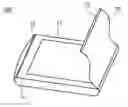
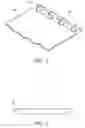
FIG. 1a is a schematic view of an embodiment of a scanner of the invention;
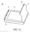
FIG. 1b is a schematic view of another embodiment of a scanner of the invention;
FIG. 1c is a schematic view of another embodiment of a scanner of the invention;
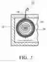
FIG. 2 is a schematic view of a flexible cover accommodated in a main body of the scanner;
FIG. 3 is a schematic view depicting a flexible cover connected to a shaft of the embodiment of FIGS. 1a to 1c;
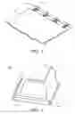
FIG. 4 is a schematic view of an embodiment of a scanner of the invention;
FIG. 5 is a schematic view depicting a flexible cover connected to a shaft of the embodiment of FIG. 4; and
FIG. 6 is a cross section of a flexible cover of the invention.
DETAILED DESCRIPTIONReferring to FIG. 1a, a scanner 100 comprises a main body 10 and a flexible cover 20 made of flexible material. The flexible cover 20 is elastic and capable of rolling up or stretching in a specific range. A latching member 22 is disposed on one end of the flexible cover 20, and a groove 16 is disposed on the main body 10 corresponding to the latching member 22. The latching member 22 engages the groove 16 to enable the flexible cover 20 to be positioned on the main body 10, thereby covering a glass plate 12 bearing a scanning object.
In this embodiment, the flexible cover 20 can be accommodated in the main body 10 as shown in FIG. 2. A shaft 30 is disposed in the main body 10. One end of the flexible cover 20 is connected to the shaft 30, and the other end thereof is free. The flexible cover 20 is wound through a slot 14 on the shaft 30 by means of rotation, and is thereby accommodated in the main body 10. Only the latching member 22 is left outside the main body 10. In addition, as the shaft 30 is disposed near one end of the main-body 10, motion of a scan module (not shown) is not affected.
In this embodiment, an elastic element (spring) 40 connects the flexible cover 20 and the shaft 30 as shown in FIG. 3. When an object is to be scanned, the flexible cover 20 is pulled to the front end of the main body 10 and stretched tightly, elongating the elastic element 40. Latching member 22 is engaged to the groove 16 enabling the flexible cover 20 to cover the glass plate 12. When the scan is complete, the flexible cover 20 is pulled up and released. Because the elastic element 40 is elongated, the shaft 30 is rotated by the elastic force to roll up the flexible cover 20, whereby the flexible cover 20 is accommodated in the main body 10. When the scanner 100 is not used, the flexible cover 20 can be pulled out to cover the glass plate 12 for the sake of protection.
Another embodiment of the invention is depicted in FIG. 1b. A ferromagnetic element 22′ is disposed on one end of the flexible cover 20, and a magnet 16′ is disposed on the main body 10 corresponding to the ferromagnetic element 22′. The ferromagnetic element 22′ is attracted to the magnet 16′ to enable the flexible cover 20 to engage the main body 10, thereby the flexible cover 20 covering the glass plate 12.
Another embodiment of the invention is depicted in FIG. 1c. At least one hole 22″ is formed on the flexible cover, and at least one latch 16″ is disposed on the main body 10 corresponding to the hole 22″. The latch 16″ engages the hole 22″ enabling the flexible cover 20 to engage the main-body 10, thereby the flexible cover 20 covering the glass plate 12.
FIG. 4 depicts another embodiment of the invention. In this embodiment, the flexible cover 20 is connected to the shaft 30 by a link element 60. The shaft 30 is connected to a knob 90 protruding from the main body 10. When the knob 90 is rotated, the shaft 30 is rotated and the flexible cover 20 is wound on the shaft 30. When an object is to be scanned, the flexible cover 20 is pulled out and the latching member 22 is engaged with the groove 16. When the scan is finished, the flexible cover 20 is pulled up and the knob 90 is rotated to wind the flexible cover 20 on the shaft 30.
In general, the glass plate 12 is depressed from the main body 10. As shown in FIG. 4, The flexible cover 20 has a central portion thicker than the lateral sides thereof to easily cover the depressed glass plate 12. Thus the scanning object is pressed closely against the glass plate 12 for better scan quality.
For even better scan quality, the described latching element, ferromagnetic element, hole and the like can be disposed on lateral sides of the flexible cover 20, and the corresponding groove, magnet, and latch can also be disposed on the main body 10.
While the invention has been described by way of example and in terms of preferred embodiment, it is to be understood that the invention is not limited thereto. To the contrary, it is intended to cover various modifications and similar arrangements (as would be apparent to those skilled in the art). Therefore, the scope of the appended claims should be accorded the broadest interpretation so as to encompass all such modifications and similar arrangements.
Claims
What is claimed is:1. A scanner, comprising:
a main body;
a flexible cover made of flexible material joined to the main body, and covering a scanning object.
2. The scanner as claimed in claim 1 further comprising a shaft within the main body, wherein a first end of the flexible cover is connected to the shaft, and the flexible cover is wound on the shaft when accommodated in the main body.
3. The scanner as claimed in claim 2 further comprising an elastic member connecting the flexible cover and the shaft, wherein the flexible cover is wound on the shaft by elastic force of the elastic member.
4. The scanner as claimed in claim 3 further comprising a latching element disposed on a second end of the flexible cover which is opposing to the first end of the flexible cover, wherein the latching element engages the main body to enable the flexible cover to engage the main body, thereby covering the scanning object.
5. The scanner as claimed in claim 3 further comprising a ferromagnetic element disposed on a second end of the flexible cover which is opposing to the first end of the flexible cover and a magnet disposed on the main body, wherein the ferromagnetic element is attracted to join with the magnet to enable the flexible cover to engage the main body, thereby covering the scanning object.
6. The scanner as claimed in claim 3 further comprising at least one hole defined on a second end of the flexible cover which is opposing to the first end of the flexible cover and at least one latch disposed on the main body, wherein the latch engages the hole to enable the flexible cover to engage the main body, thereby covering the scanning object.
7. The scanner as claimed in claim 3 further comprising at least one hole defined on a second end of the flexible cover which is opposing to the first end of the flexible cover and at least one latch disposed on one side of the main body, wherein the latch engages the hole to enable the flexible cover to engage the main body, thereby covering the scanning object.
8. The scanner as claimed in claim 2 further comprising a link element connecting the flexible cover and the shaft, wherein the flexible cover is wound on the shaft by rotation of the shaft.
9. The scanner as claimed in claim 8 further comprising a knob disposed on the main body and connected to the shaft, wherein the shaft is rotated by rotating the knob so as to wind the flexible cover on the shaft.
10. The scanner as claimed in claim 9 further comprising a latching element disposed on a second end of the flexible cover which is opposing to the first end of the flexible cover, wherein the latching element engages the main body to enable the flexible cover to engage the main body, thereby covering the scanning object.
11. The scanner as claimed in claim 9 further comprising a ferromagnetic element disposed on a second end of the flexible cover which is opposing to the first end of the flexible cover and a magnet disposed on the main body, wherein the ferromagnetic element is attracted to join with the magnet to enable the flexible cover to engage the main body, thereby covering the scanning object.
12. The scanner as claimed in claim 9 further comprising at least one hole defined on a second end of the flexible cover which is opposing to the first end of the flexible cover and at least one latch disposed on the main body, wherein the latch engages the hole to enable the flexible cover to engage the main body, thereby covering the scanning object.
13. The scanner as claimed in claim 9 further comprising at least one hole defined on a second end of the flexible cover which is opposing to the first end of the flexible cover and at least one latch disposed on one side of the main body, wherein the latch engages the hole to enable the flexible cover to engage the main body, thereby covering the scanning object.
14. The scanner as claimed in claim 1, wherein the flexible cover comprises two lateral sides and one central portion which is thicker than the two lateral sides.
Images & Drawings included:

Sources:
- United States Patent and Trademark Office - verify current appl. status at the USPTO↗
Similar patent applications:
- » 20180097952
Flexible scanner cover
Recent applications in this class:
- » 20250175562 2025-05-29
CIRCUIT BOARD-EQUIPPED APPARATUS - » 20240171690 2024-05-23
Image forming apparatus including a double-structured bottle cover - » 20230262176 2023-08-17
Image reading apparatus in which member to make reference member move is provided to be able to retract - » 20210297542 2021-09-23
IMAGE ACQUISITION DEVICE - » 20200382666 2020-12-03
Image reading device - » 20200106905 2020-04-02
Scanning apparatus - » 20190260893 2019-08-22
Image reading apparatus and image forming apparatus - » 20190260892 2019-08-22
Image reading device and image forming apparatus - » 20180316809 2018-11-01
Image reading apparatus and image forming apparatus - » 20180063346 2018-03-01
Image forming apparatus