Device for auxiliary units of an internal combustion engine
US20060240926A1
2006-10-26
10/557,161
2004-04-16
✅ Patent granted
US 7,347,309 B2
2008-03-25
WO; PCT/EP2004/004027; 20040416
WO; WO2004/101973; 20041125
Richard M. Lorence | Edwin A Young
2024-12-01
Abstract:
In a device for damping rotary oscillations in a traction mechanism drive for auxiliary units of an internal combustion engine, having an overrunning clutch (27), which is arranged between a pulley (25) and a hub (26), according to the invention a locking device (33) is located between the pulley (25) and the hub (26), axially behind the overrunning clutch (27). This locking device includes an inner ring (34), which surrounds and is secured to the hub (26), and outer ring (35), which surrounds the inner ring (34) with a radial clearance and is secured to the pulley (25), and a plurality of retaining balls (36) which, together with compression springs (37), are arranged in radial bores (39) in the outer ring (35).
Assignee:
- INA SCHAEFFLER KG 124 🇩🇪 Herzogenaurach, Germany
Interested in similar patents?
Get notified when new applications in this technology area are published.
Classification:
F16D43/208 » CPC main
Automatic clutches actuated entirely mechanically controlled by torque, e.g. overload-release clutches, slip-clutches with means by which torque varies the clutching pressure of the ratchet type with intermediate balls or rollers moving radially between engagement and disengagement
F02B67/06 » CPC further
Engines characterised by the arrangement of auxiliary apparatus not being otherwise provided for, e.g. the apparatus having different functions; Driving auxiliary apparatus from engines, not otherwise provided for of mechanically-driven auxiliary apparatus driven by means of chains, belts, or like endless members
F16D45/00 » CPC further
Freewheels or freewheel clutches combined with automatic clutches
F16D11/16 » CPC further
Clutches in which the members have interengaging parts with clutching members movable otherwise than only axially
F16D41/066 » CPC further
Freewheels or freewheel clutches with intermediate wedging coupling members between an inner and an outer surface the intermediate members wedging by rolling and having a circular cross-section, e.g. balls all members having the same size and only one of the two surfaces being cylindrical
F16H55/36 IPC
Elements with teeth or friction surfaces for conveying motion; Worms, pulleys or sheaves for gearing mechanisms; Friction members Pulleys
F16H55/49 IPC
Elements with teeth or friction surfaces for conveying motion; Worms, pulleys or sheaves for gearing mechanisms; Friction members; Pulleys Features essential to V-belts pulleys
F16D43/16 » CPC further
Automatic clutches actuated entirely mechanically controlled by angular speed with centrifugal masses actuating the clutching members directly in a direction which has at least a radial component; with centrifugal masses themselves being the clutching members with clutching members having interengaging parts
F16D47/04 IPC
Systems of clutches, or clutches and couplings, comprising devices of types grouped under at least two of the preceding guide headings of which at least one is a freewheel
F16D41/064 IPC
Freewheels or freewheel clutches with intermediate wedging coupling members between an inner and an outer surface the intermediate members wedging by rolling and having a circular cross-section, e.g. balls
Description
FIELD OF THE INVENTIONThe invention relates to a device for damping rotary oscillations in a traction mechanism drive for auxiliary units of an internal combustion engine, having an overrunning clutch, which is arranged between a pulley and a hub that is rotationally fixedly connected to an input shaft of an auxiliary unit.
BACKGROUND OF THE INVENTIONOn account of the increase in efforts of the automotive industry to reduce average fuel consumption, by way of example a belt-driven starter-generator is used in an internal combustion engine. This new technology is preferably used in combination with direct injection gasoline or diesel engines. On account of the unfavorable power train dynamics of these engines, there is an obvious desire for it to be possible to use a traction mechanism drive with an overrunning alternator pulley (OAP). In this context, it is intended to make use of the tried-and-tested operation of an overrunning alternator. An overrun of this type combined with a pulley is known, for example, from document DE 195 11 188 A1.
SUMMARY OF THE INVENTIONThe invention is based on the object of allowing the internal combustion engine to be started using the generator. For this purpose, a starting mechanism which, after a starting operation, automatically decouples the starting function from the pulley as a function of the engine speed, is to be integrated in the overrunning alternator pulley.
According to the invention, this object is achieved by virtue of the fact that a locking device, which includes an inner ring that surrounds and is secured to the hub, an outer ring that surrounds the inner ring with a radial clearance and is secured to the pulley, and a plurality of retaining balls that are arranged together with compression springs in radial bores in the outer ring, are pressed toward the inner ring by the compression springs and are radially supported against the inner ring within spherical caps machined into the inner ring, is arranged between the pulley and the hub, axially behind the overrunning clutch.
This results in locking between the pulley and the hub, which is connected to the input shaft of the generator, when stationary and at low engine speeds, so that the generator auxiliary unit can be used as a starter. At higher engine speeds, the retaining balls leave the spherical caps of the inner ring as a result of centrifugal forces and release the inner ring and the hub connected to it from the pulley. In this case, only the overrunning clutch acts between the hub and the pulley, and the auxiliary unit can be used as a generator. The invention therefore makes it possible to use a starter-generator in the belt drive of an internal combustion engine.
To ensure reliable operation of the locking device, the radial bores and the spherical caps aligned with them, on the outer ring and the inner ring, respectively, may be arranged in succession at regular intervals in the circumferential direction, while the inner ring may be provided with an encircling guide groove, which is arranged between the individual spherical caps, with run-in ramps for the retaining balls.
The overrunning clutch may have a bearing outer ring or bearing inner ring, which is produced by a chipless process as a sheet-metal part and on which clamping ramps that interact with clamping rolls are formed, the bearing outer ring or bearing inner ring, at least on one side, extending axially beyond the region of the clamping ramps and forming a raceway for a rolling-contact bearing. The use of the same components for the overrunning clutch and for the rolling-contact bearing arrangement, i.e. the formation of a common bearing inner ring or bearing outer ring, allows the device to be of inexpensive design.
The assembly comprising the overrunning clutch, the rolling-contact bearings and the locking device with the inner ring, the outer ring, the retaining balls and the compression springs may be arranged within the axial extent of the pulley. This means that no additional space which exceeds the axial length of the pulley is required for the device according to the invention.
BRIEF DESCRIPTION OF THE DRAWINGAn exemplary embodiment of the invention is illustrated in the drawing and described in more detail below by comparison with a device according to the known prior art. In the drawing:
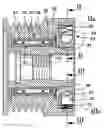
FIG. 1 shows a pulley assembly according to the invention, which is provided with a locking device, in longitudinal section;
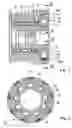
FIG. 2 shows the locking device in the locked position corresponding to circle IIa in a cross section on line II-II from FIG. 1;
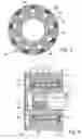
FIG. 3 shows the locking device in the unlocked position corresponding to circle IIIA in a cross section on line III-III from FIG. 1;
FIG. 4 shows a pulley assembly according to the known prior art.
DETAILED DESCRIPTION OF THE INVENTIONA known device for damping rotary oscillations which is illustrated in FIG. 4 surrounds an input shaft 1 which, for example, forms part of an alternating-current generator or an air-conditioning compressor. The input shaft is driven via a pulley 2 and a drive belt (not shown in more detail) by an output disc connected to the crankshaft of an internal combustion engine. In its interior, the pulley 2 has a reinforcing ring 3. An assembly comprising an overrunning clutch 5 and two cylindrical-roller bearings 6 and 7 is placed in a bore 4 in this ring. In this arrangement, a common bearing outer ring 8 and a common bearing inner ring 9 are provided for the assembly. The bearing inner ring 9 has a plurality of clamping ramps which are distributed over the circumference, are not illustrated in more detail and interact with a corresponding number of clamping rolls 10. The clamping rolls are guided in a cage 11 and prestressed with respect to the clamping ramps by means of springs (not shown in more detail). The bearing outer ring 8 is designed substantially in the form of a sleeve and has a constant internal diameter over its entire length, forming raceways for the cylindrical-roller bearings 6 and 7 and the clamping rolls 10.
At its end remote from the auxiliary unit, the bearing inner ring 9 is provided with a radially outwardly directed flange 12 which at the end side is supported against a stop disc 13 fixed in the reinforcing ring 3. At its other axial end, the bearing inner ring 9 has a shoulder 14 which is designed, for example, in the form of a tooth and engages in individual longitudinal grooves 15, which in turn form part of a hub 16. At one end, the bearing outer ring 8 has a first flange 17, behind which the flange 12 of the bearing inner ring 9 engages. A second flange 18 of the bearing outer ring 8, which is provided at its end facing the auxiliary unit, engages behind a cage 19 of the cylindrical-roller bearing 7. A radial sealing ring 20, which is fitted into the pulley 2 and forms a sliding seal with the bearing inner ring 9, is arranged adjacent to this second flange 18. To secure the hub 16 to the input shaft 1, the hub 16 has an internal screw thread 21, a multi-tooth profile 22, which is designed as serrated toothing for an assembly tool to engage on, being provided in the interior of the hub 16 at a distance from this internal screw thread 21. At its end remote from the auxiliary unit, the pulley 2 is closed off by means of a cover 23 which has an axially projecting edge 24. The latter is snapped in at the circumference of the pulley 2.
A device according to the invention illustrated in FIGS. 1 to 3 is of substantially the same construction as the device illustrated in FIG. 4. However, it differs from the latter by virtue of the fact that, in addition to the assembly comprising an overrunning clutch 27 with a bearing outer ring 28, a bearing inner ring 29, clamping rolls 30 and rolling-contact bearings 31 and 32, a locking device 33 is arranged between its pulley 25 and its hub 26. This locking device 33 comprises an inner ring 34, an outer ring 35, retaining balls 36 and compression springs 37.
The inner ring 34 has been fitted onto the hub 26 from its end and fixedly connected thereto. It includes a plurality of recesses leading from its outer surface in the form of spherical caps 38 which are arranged successively at regular intervals in the circumferential direction. The outer ring 35 concentrically surrounds the inner ring 34 with a radial clearance. It is inserted in an annular concentric recess of the pulley 25 from an end side and secured to the pulley. A continuous radial bore 39 is in each case arranged in the outer ring 35, coaxially with respect to a spherical cap 38 of the inner ring 34, and a retaining ball 36 and a compression spring 37 are fitted into this radial bore 39.
The radial bores 39 in the outer ring 35 can be closed off at the outer surface of the outer ring 35 using plugs 40, on which one end of the compression springs 37 is in each case supported. The respective other ends of the compression springs 37 bear against the inserted retaining balls 36 and press them into the spherical caps 38 of the inner ring 34. In the at-rest state of the device, the retaining balls 36 are each positioned approximately half in the spherical caps 38 of the inner ring 34 and approximately half in the radial bores 39 in the outer ring 35. They bridge the radial clearance between the inner ring 34 and the outer ring 35 and in this position retain the rings with respect to one another. In the operating state, the retaining balls 36, under centrifugal force, are pressed into the radial bores 39 to a greater or lesser extent depending on the rotational speed of the device, counter to the action of the compression springs 37, so that as a result the rings 34 and 35 are unlocked from one another.
The device according to the invention operates as follows: while the internal combustion engine is starting up, a torque is introduced from the starter-generator shaft via the hub 26 into the inner ring provided with the spherical caps 38. This starting torque is transmitted by means of the spherical caps 38 and the retaining balls 36 to the outer ring 35, which is positioned in a positively locking manner in the pulley 25 and acts as a ball support. The internal combustion engine is started by means of a drive belt surrounding the pulley 25. After a limit rotational speed has been reached, the retaining balls 36, as a result of the centrifugal force, move completely into the radial bores 39 in the outer ring 35, counter to the action of the compression springs 37, and are thereby disengaged from the inner ring 34. The over-running pulley 25 is then decoupled from the generator mass and can perform its normal function. After the internal combustion engine has been switched off, and as a result the rotational speed has dropped back below the limit rotational speed, the retaining balls 36 move back into the locking position or engine starting position under the action of the prestressed compression springs 37. This engine starting position is found automatically. To achieve this in a defined way, the inner ring 34 has a radially encircling guide groove 41 with run-in ramps which are arranged between the individual spherical caps 38 of the inner ring 34.
| 1 | Input shaft |
| 2 | Pulley |
| 3 | Reinforcing ring |
| 4 | Bore |
| 5 | Overrunning clutch |
| 6 | Cylindrical-roller |
| bearing | |
| 7 | Cylindrical-roller |
| bearing | |
| 8 | Bearing outer ring |
| 9 | Bearing inner ring |
| 10 | Clamping roll |
| 11 | Cage |
| 12 | Flange |
| 13 | Stop disc |
| 14 | Shoulder |
| 15 | Longitudinal groove |
| 16 | Hub |
| 17 | First flange |
| 18 | Second flange |
| 19 | Cage |
| 20 | Radial sealing ring |
| 21 | Internal screw thread |
| 22 | Multi-toothed profile |
| 23 | Cover |
| 24 | Edge |
| 25 | Pulley |
| 26 | Hub |
| 27 | Overrunning clutch |
| 28 | Bearing outer ring |
| 29 | Bearing inner ring |
| 30 | Clamping roll |
| 31 | Rolling-contact bearing |
| 32 | Rolling-contact bearing |
| 33 | Locking device |
| 34 | Inner ring |
| 35 | Outer ring |
| 36 | Retaining ball |
| 37 | Compression spring |
| 38 | Spherical cap |
| 39 | Radial bore |
| 40 | Plug |
| 41 | Guide groove |
Claims
1. Device for damping rotary oscillations in a traction mechanism drive for auxiliary units of an internal combustion engine, having an overrunning clutch (27), which is arranged between a pulley (25) and a hub (26) that is rotationally fixedly connected to an input shaft of an auxiliary unit, characterized in that a locking device (33), which includes an inner ring (34) that surrounds and is secured to the hub (26), an outer ring (35) that surrounds the inner ring (34) with a radial clearance and is secured to the pulley (25), and a plurality of retaining balls (36) that are arranged together with compression springs (37) in radial bores (39) in the outer ring (35), are pressed toward the inner ring (34) by the compression springs (37) and are radially supported against the inner ring within spherical caps (38) machined into the inner ring (34), is arranged between the pulley (25) and the hub (26), axially behind the overrunning clutch (27).
2. The device as claimed in claim 1, characterized in that the radial bores (39) and the spherical caps (38) aligned with them, on the outer ring (35) and the inner ring (34), respectively, are arranged in succession at regular intervals in the circumferential direction.
3. The device as claimed in claim 1, characterized in that the inner ring (34) is provided with an encircling guide groove (41), which is arranged between the individual spherical caps (38), with run-in ramps for the retaining balls (36).
4. The device as claimed in claim 1, characterized in that the overrunning clutch (27) has a bearing outer ring (28) or bearing inner ring (29), which is produced by a chipless process as a sheet-metal part and on which clamping ramps that interact with clamping rolls (30) are formed, the bearing outer ring (28) or bearing inner ring (29), at least on one side, extending axially beyond the region of the clamping rolls (30) and forming a raceway for a rolling-contact bearing (31, 32).
5. The device as claimed in claim 4, characterized in that the assembly comprising the overrunning clutch (27), the rolling-contact bearings (31, 32) and the locking device (33) with the inner ring (34), the outer ring (35), the retaining balls (36) and the compression spring (37) is arranged within the axial extent of the pulley (25).
Images & Drawings included:
Sources:
- United States Patent and Trademark Office - verify current appl. status at the USPTO↗
Similar patent applications:
Recent applications in this class:
- » 20240410429 2024-12-12
ADJUSTMENT DRIVE - » 20220403896 2022-12-22
Anti-back drive components for a valve actuator assembly - » 20220389977 2022-12-08
Shaft lock - » 20210372492 2021-12-02
Torque limiter assembly - » 20200284307 2020-09-10
Anti-back drive components for a valve actuator assembly - » 20190010997 2019-01-10
Torque limiter assembly - » 20110042176 2011-02-24
Torque limiter - » 20060124331 2006-06-15
Rotary tool - » 20060111192 2006-05-25
Techniques for controlling transfer of torque using detent members responsive to radial force - » 17752569 2023-09-05
Torque limiter with automatic reset ability
Recent applications for this Assignee:
- » 20080108444 2008-05-08
BEARING ARRANGEMENT FOR SUPPORTING A TRUNNION OF AN UNIVERSAL JOINT - » 20080044646 2008-02-21
WEAR-RESISTANT COATING AND PROCESS FOR PRODUCING IT - » 20080044116 2008-02-21
Linear rolling bearing - » 20070259745 2007-11-08
Centre of Rotation Support for an Assembly - » 20070204824 2007-09-06
Camshaft adjuster - » 20070101956 2007-05-10
Device and method for determining the angle of rotation between a camshaft and a crankshaft in an internal combustion engine - » 20070096459 2007-05-03
Rotating passage - » 20070019892 2007-01-25
Guide rail for guide carriages of a linear guideway - » 20070012272 2007-01-18
Valve drive - » 20070009191 2007-01-11
Radial/axial bearing