Display for handguns and folding knives
US20060243614A1
2006-11-02
11/111,001
2005-04-21
Abstract:
A transparent support displays handguns and folding knives. The display also supports paper, card and transparent film media to show a message in association with the displayed item.
Interested in similar patents?
Get notified when new applications in this technology area are published.
Classification:
A47F7/00 » CPC main
Show stands, hangers, or shelves, adapted for particular articles or materials
B65D85/00 IPC
Containers, packaging elements or packages, specially adapted for particular articles or materials
Description
COPYRIGHT NOTICEA claim for copyright (© 2005 by Joel W. Benson) is made for the display design, as illustrated in all drawings provided herewith. The copyright owner has no objection to the facsimile reproduction by anyone of this patent document, the drawings, or this patent disclosure, as it appears in the U.S. Patent and Trademark Office patent file or record, but otherwise reserves all copyright rights whatsoever.
BACKGROUND1. Technical Field
The invention concerns a support for displaying handguns or folding knives and, more particularly, to such a support that is transparent, provides easy access to displayed items, and also shows a message or messages in association with the displayed items.
2. Background Information
There is significant interest in collecting handguns and folding knives having a unique and attractive appearance. While these things are tools that have a specific useful purpose, they nonetheless are often in themselves works of art that are appropriate for display.
Displays of metal, wood or even plastic are commercially available, but such prior displays have often not been particularly attractive and may even obstruct a clear view of the displayed item. Also, while displays for handguns are available, an attractive display for folding knives is not presently known. Moreover, there is no known display that can provide an attractive support for both handguns and folding knives. Also, no known display can provide custom, interchangeable messages of different types in association with a displayed item.
It would, therefore, be desirable to provide a single support that can attractively display both handguns and folding knives in a preferred orientation. It would also be desirable to provide such a display that is transparent or translucent and therefore does not interfere with any visual aspect of the displayed item. It would also be advantageous to provide such a display support that can accommodate removable messages to enhance the display, without interfering with the view of the displayed item.
BRIEF SUMMARYThe display of the invention supports handguns of various sizes by engaging the front, lower edge of the barrel and the lower edge at the front of the pistol grip, so that the gun is presented in an attractive orientation with the barrel pointed down. The same display may be used to support a folding knife that is partially extended in an inverted-V orientation, to show both the blade and handle of the knife.
The display support is preferably made of transparent acrylic, any other plastic, or glass so that the supported item can be viewed clearly without any interference from the support. The support also includes a front window that is mounted to receive and display any desirable message written on a rectangular piece of paper, cardstock, or plastic film. The display also has a front rail with a slot that may be used to support a card, for example a business card, in association with the displayed item. This rail is also dimensioned so that it can support any relatively small item, for example a bullet, in association with the displayed knife or handgun.
The display is therefore very versatile in that it can display either handguns or folding knives in an attractive manner, while also displaying cards, special messages or even associated small items. DR
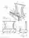
DETAILED DESCRIPTION OF THE DRAWINGS IN THE PRESENTED PREFERRED EMBODIMENTSFIG. 1 illustrates a perspective view of a first embodiment of a handgun and folding knife display;
FIG. 2 illustrates a front elevation view of the display of FIG. 1;
FIG. 3 illustrates an end elevation view of the display of FIG. 1, which is a mirror image of the opposite end;
FIG. 4 illustrates a front elevation view of the display of FIG. 1 supporting a handgun;
FIG. 5 illustrates a front elevation view of the display of FIG. 1 supporting a partially extended folding knife;
FIG. 6 illustrates a front elevation view of the display of FIG. 1 simultaneously supporting two handguns;
FIG. 7 illustrates a front elevation view of the display of FIG. 1 with message media supported behind a front transparent display panel;
FIG. 8 illustrates a perspective view of the handgun and folding knife display in association with message media that may be made, for example of paper, cardstock or transparent film.
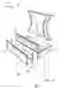
FIG. 9 illustrates an exploded perspective view of the components of the handgun and folding knife display;
FIG. 10 illustrates a second embodiment of the handgun and folding knife display which has a prism shape, but the same operation as the display of the first embodiment.
DETAILED DESCRIPTION OF THE DRAWINGS IN THE PRESENTLY PREFERRED EMBODIMENTSIn the drawings, illustrated elements are drawn to scale, and the same reference numerals designate like elements in several views. FIG. 1 shows a perspective view of a first embodiment of a display for handguns and folding knives. The illustrated display is made of transparent acrylic components, but it could be made of any other suitable materials such as glass, metal, various types of plastic, or wood. At present, a transparent material is preferred, because it does not interfere with the view of whatever handgun or folding knife is displayed.
The display of FIG. 1 is shown with a base 3 that is 6 inches (15.24 cm) long, 3 inches (7.62 cm) wide, and 1 inch (2.54 cm) thick in the vertical direction with respect to FIG. 1. A back support 5 is affixed at the rear edge of the base 3, for example by a transparent glue or epoxy. The back support is 4 inches (10.16 cm) high and 0.625 inch (1.59 cm) thick. The lateral edges 7 of the back support are sculpted with a concave profile and are beveled to provide an attractive and shiny appearance that highlights the displayed item. The concave sculpted lateral edges also allow easy access to place and remove a displayed item.
A front rail 9 is affixed at the front edge of the base 3, for example by the same transparent glue or epoxy that was used to affix the back support 5 to the base 3. Although glue or epoxy can be used to affix separate components as described, it should be understood that the entire display could be cut or formed from a single piece of plastic, glass, or other material in a known manner.
The front rail 9 has a lateral slot 11 formed in its top edge, for example by cutting with a circular saw. This cutting gives the area of the slot 11 an attractive translucent appearance. Thus, from the front of the display of FIG. 1, it appears that an embedded light white line has been drawn across the length of the front rail 9. The rail 9 is 0.5 inch (1.27 cm) high and 0.375 inch (0.95 cm) wide; and the slot is 0.125 inch (0.32 cm) wide and 0.1875 inch (0.48 cm) deep.
As shown in FIGS. 2 and 3, a transparent front display plate 13 is affixed to the front face 17 of the base 3, for example by a peripherally applied tape 14 at the side and bottom edges of the plate 13. The tape 14 affixes the plate to the front 17 of the base 3, while holding the plate 13 in spaced relation to the front of the base 3, for example to provide a display space 15 the thickness of a piece of paper or cardboard stock. The front plate is 1.5 inch (3.81 cm) high and 0.125 inch (0.32 cm) thick. Transparent silicon disks 19 are affixed at the bottom of the base 3 to support the base on an underlying support surface (not shown), for example a table, without scratching the support surface.
FIGS. 2 and 3 respectively illustrate a front view and right end view of the display of FIG. 1, with the previously specified numerals referencing the described parts. The end view of FIG. 3 shows the spacer tape 14 which creates the display space 15 between the front display plate 13 and the front face 17 of the base 3.
FIGS. 4, 5 and 6 illustrate a front view of the display of FIGS. 1-3 as a support for handguns and a folding knife. As shown in FIG. 4, and with reference also to FIG. 1, a handgun 21 is supported in an attractive muzzle down orientation by engaging the end edges 4A and 4B of the base 3. As shown in FIG. 4, the underside of a barrel 23 of the handgun 21 is supported in frictional engagement with the left edge 4B of the base 3 of the display, and the bottom-front edge of the grip 25 of the handgun frictionally engages the right end edge 4A of the base 3. The handgun 21 then tilts backward and rests against the rear surface 27 of the back support 5. The handgun is therefore securely supported at 3 points on the display 1.
It should be understood that the display 1 will support handguns of varying sizes and shapes in the orientation illustrated at FIG. 4. The dimensions of the display are selected so that the front barrel and grip of any hand gun will be supported in the manner illustrated in FIG. 4, for handguns having a wide variation of barrel and grip lengths. The display 1 can also support revolvers of different sizes and shapes in the same manner. It will be appreciated by reference to FIG. 4 that the handgun is displayed in an attractive and relatively safe barrel-down orientation.
FIG. 5 illustrates the display 1 supporting a folding knife 29. As shown in FIG. 5, the folding knife is displayed in a stable, partially open orientation wherein the pointed end of a blade 31 and the handle end 33 of the knife are supported on the top surface of the base 3. The stability of this support orientation is enhanced by the pressure of the point of the blade 31 of the knife against the relatively soft top plastic surface of the base 3. If care is taken in placing the knife, it has been found that the tip of the knife blade will not scratch or mar the top surface of the base 3.
FIG. 6 illustrates an alternative support orientation for two handguns 21 on the display support 1. As shown in FIG. 6, the handguns 21 are supported by engagement of a rear grip point 35 against a surface (not shown) that supports the display 1. Support points 37 at the rear of the handguns 21 engage the top surface of the base 3 and the guns lean against the rear surface 27 or a top edge 39 of the back support 5 to hold the guns in an attractive upward orientation.
Although it has been found that handguns and knives supported as shown in FIGS. 4-6 are quite stable, it is possible that the displayed handgun or knife could be inadvertently dislodged from the display. Accordingly, it is preferred to display handguns or knives on the display supports 1 within an enclosed area, for example a case or safe that contains the displayed handguns or knives. Also, of course, as a point of safety, handguns should always be displayed in an unloaded condition, with associated magazines either empty or removed from the handgun.
FIG. 7 illustrates the display 1 of FIGS. 1-6 with a sample of a message that may be displayed by a rectangular piece of paper, cardboard stock or transparent film that is disposed (as shown in FIGS. 3 and 8) in the space 15 between the front display plate 13 and front face 17 of the base.
FIG. 8 illustrates a rectangular-shaped image or message media 41 that may be placed within the display space 15 at the front of the display. Printed characters, images or combined images and characters may be formed on the message media 41 in any desired colors and inserted into the display space 15, as shown in FIG. 7, to provide a suitable visual display in association with the handgun or folding knife that is displayed. The printed characters and/or images may be shown on standard typing paper, a heavier cardstock, or a transparent plastic film.
If such a message display is used, it should be understood that the message may be readily changed by removing the message media and substituting alternative media with a new message. The term “message” is here used in its broadest sense to refer to alphanumeric or other characters, images, or combinations of such characters and images. Of course, if no message is provided, the front of the base of the display will be transparent, even if the front display plate 13 is provided.
Information may also be displayed on any suitable business-card size message media 43 that is engaged in the lateral slot 11 of the front rail 9. The slot 11 is dimensioned so that the card will be held upright with a slight backwards lean to display a message in association with a handgun or folding knife that is displayed. The top surface of the front rail 9 may also be used to display other small items as well. For example, handgun ammunition, such as cartridges or bullets (not shown), can be supported on the top surface of the front rail 9 in association with a displayed handgun or folding knife.
FIG. 9 illustrates an exploded view of the components of the display of FIGS. 1-8. As shown in FIG. 9, the back support 5, base 3, front rail 9, front display plate 13, transparent spacer tape 14, and silicon support disks 19 are adhered together as previously discussed to provide the structure of an embodiment of a transparent display.
Alternative embodiments of a display of this type may be provided, without departing from the invention. Thus, for example, the front display plate 13 and associated transparent spacer tape 14 may be removed and not used if the associated message display is not required. If the front display plate is removed, a cleaner, simpler appearance may be obtained for the front of the base 3.
The front rail 9 may be used as described in association with the base 3, without also using the front display plate. Thus, if the front display plate is removed, the front rail 9 may still be used to support a message displayed on business-card sized media. The front rail 9 may also be provided without the associated lateral slot 11, so that the front rail is a solid piece of material. Alternatively, the front rail 9 could be removed, thus leaving only the base 3 and back support 5 to support handguns or folding knives. Also, the silicon disks 19 may be removed if it is desired to have the base 3 rest directly on a support surface.
Other shapes could also be provided for the back support 5 without departing from the broadest aspect of the invention. The back support 5 of FIGS. 1-9 is presently preferred because it has an attractive appearance and also the sculpted shape at 7 allows the hand access to grasp a handgun or knife and easily lift away or engage it with the display. Also, while the transparent spacer tape 14 is preferred as a relatively simple and inexpensive way to adhere the front display plate 13 to the front of the base 3 and define a display space 15, other adhering materials could be employed. For example, the transparent spacer tape 14 could be replaced by a transparent or a translucent bead of silicon or epoxy to adhere the front display plate 13 to the front of the base 3 and also define the display space 15. In principle, the space 15 could also be formed by cutting a display slit into the base 3.
FIG. 10 illustrates an alternative embodiment of a display support for handguns or folding knives that has a different shape than has been described with respect to FIGS. 1-9. As shown in FIG. 10, a back support 47 may be made of transparent acrylic, like plastic material, or glass and shaped as shown to form a triangular prism, which will catch ambient light and thereby enhance a display of handguns or folding knives.
The display of FIG. 10 has a length of 6 inches (15.24 cm), a width of 2.5 inches (6.35 cm) and a 1 inch (2.54 cm) height for a base element 49. The space between a front rail 51 of previously specified dimensions and the leading edge of the back support 53 is 0.75 inch (1.91 cm), as opposed to a 2 inch (5.08 cm) space between the back support 5 and front rail 9 of the embodiment of FIGS. 1-9. Also, the height of the embodiment of FIG. 10 is 3.5 inches (8.89 cm), as opposed to a 5 inch (12.7 cm) height for the embodiment of FIGS. 1-9. The reduced height of the embodiment of FIG. 10 provides a reduced support profile for displaying handguns or folding knives. The reduced dimension between the front rail 51 and leading edge of the supporting surface 53 of the back support 47, causes the displayed handgun or folding knife to be trapped between the front rail 51 and surface 53 of the back support 47.
The embodiment of FIG. 10 may also utilize a front display plate 13 and lateral slot 11 as previously described with respect to the embodiment of FIGS. 1-9. Also, as previously discussed, the front plate 13 and lateral slot 11 may be eliminated to provide a relatively simple display, without a message display capability.
Although specific embodiments of a handgun and folding knife support and specified dimensions have been disclosed, the back support, base, and front rail elements could have different dimensions and different shapes, without departing from the invention. Also, the display could be made of any desirable materials, whether transparent, translucent or opaque. And a display as disclosed could be used to support things other than handguns or folding knives. It is therefore intended that the foregoing detailed description be regarded as illustrative rather than limiting, and that it be understood that the following claims, including all equivalents, are intended to define the scope of the invention disclosed herein.
Claims
1. A support for displaying a handgun having a barrel and hand grip, the support comprising:
a base with exposed end edges for engaging and supporting the barrel and hand grip of said handgun;
a back wall for supporting said handgun in a leaning orientation; and
a front rail for retaining said handgun on said base.
2. The support of claim 1, wherein said base has a front surface, and further including a transparent front plate, a message media, and means for affixing said front plate in spaced orientation over said front surface for receiving said message media.
3. The support of claim 1, wherein said front rail includes a lateral slot for receiving and supporting card message media.
4. The support of claim 1, wherein said back wall has concave sculpted sides.
5. The support of claim 4, wherein said sculpted sides are beveled.
6. The support of claim 1, wherein said front rail includes a lateral slot for supporting selected cartridges for a handgun.
7. The support of claim 1, wherein said back wall is prism-shaped.
8. A support for displaying a folding knife partially opened with its blade and handle oriented in an inverted V-shape, the support comprising:
a base for supporting a tip of said blade and an outer end of said handle;
a back wall for supporting said knife in a leaning orientation; and
a front rail for retaining said knife on said base.
9. The support of claim 8, wherein said base has a front surface, and further including a transparent front plate, a message media, and means for affixing said front plate in spaced orientation over said front surface for receiving said message media.
10. The support of claim 8, wherein said front rail includes a lateral slot for receiving and supporting card message media.
11. The support of claim 8, wherein said back wall has concave sculpted sides.
12. The support of claim 11, wherein said sculpted sides are beveled.
13. The support of claim 8, wherein said front rail includes a lateral slot for supporting cartridges for a handgun.
14. The support of claim 8, wherein said back wall is prism-shaped.
15. A display for an item comprising:
a base having a front surface and a top surface, said top surface for supporting said item;
a back wall affixed to said base for supporting said item in a leaning orientation;
a front rail affixed to said base and having a slot formed in its top surface;
a transparent front plate; and
means for affixing said front plate in spaced orientation over said front surface of the base and defining a display space therebetween.
16. The display of claim 15, further including,
first message media for selectively engaging said slot; and
second message media disposed in said display space and viewed through said front plate.
17. The display of claim 15, wherein said item is a handgun.
18. The display of claim 15, wherein said item is a folding knife.
19. The display of claim 15, wherein said base, back wall, and front rail are made of transparent material.
20. The display of claim 15, wherein said back wall has concave sculpted and beveled sides.
21. The display of claim 15, wherein said back wall is prism-shaped.
Images & Drawings included:


Sources:
- United States Patent and Trademark Office - verify current appl. status at the USPTO↗
Recent applications in this class:
- » 20220338646 2022-10-27
DISPLAY SYSTEM - » 20210037993 2021-02-11
Door hardware display system - » 20210037992 2021-02-11
Quickly customizable systems that secure laptops to display tables and other display surfaces - » 20210015274 2021-01-21
Adjustable apparatuses that secure tablet computing devices and keyboards to display tables - » 20200359810 2020-11-19
Display mount for toilet seat assembly - » 20200008589 2020-01-09
Adjustable size apparatuses that secure portable electronic devices to display tables - » 20190365121 2019-12-05
Piece of furniture having at least one support rod - » 20180352975 2018-12-13
Pillow display cart - » 20180303254 2018-10-25
Modular vape gear shelf and storage - » 20170367503 2017-12-28
PILLOW DISPLAY CART