Display unit, information apparatus with display unit, and method of assembling display unit
US20060243638A1
2006-11-02
11/269,818
2005-11-09
✅ Patent granted
US 8,218,302 B2
2012-07-10
-
-
Amr Awad | Michael Pervan
2028-11-07
Abstract:
A display unit having a display device; a first case with an opening, covering the front surface of the display device; and a second case covering the back surface of the display device. The first case has a frame part enclosing the opening, and a side wall extending from the frame part toward the second case over the entire circumference of the frame part. The display device is placed on the frame part in a state of being enclosed by the side wall. At least two support rods are fixed to the side wall and press the display device. The part number, man-hours, and weight of the cabinet can be reduced.
Assignee:
- PANASONIC CORPORATION 20,737 🇯🇵 Osaka, Japan
Interested in similar patents?
Get notified when new applications in this technology area are published.
Classification:
G06F1/1616 » CPC main
Details not covered by groups - and; Constructional details or arrangements for portable computers with several enclosures having relative motions, each enclosure supporting at least one I/O or computing function with folding flat displays, e.g. laptop computers or notebooks having a clamshell configuration, with body parts pivoting to an open position around an axis parallel to the plane they define in closed position
G06F1/1637 » CPC further
Details not covered by groups - and; Constructional details or arrangements for portable computers; Constructional details or arrangements of portable computers not specific to the type of enclosures covered by groups - Details related to the display arrangement, including those related to the mounting of the display in the housing
B65D5/52 IPC
Rigid or semi-rigid containers of polygonal cross-section, e.g. boxes, cartons or trays, formed by folding or erecting one or more blanks made of paper; Details of containers or of foldable or erectable container blanks; Integral, inserted or attached portions forming internal or external fittings External stands or display elements for contents
G06F1/16 IPC
Details not covered by groups - and Constructional details or arrangements
G06F3/038 IPC
Input arrangements for transferring data to be processed into a form capable of being handled by the computer; Output arrangements for transferring data from processing unit to output unit, e.g. interface arrangements; Input arrangements or combined input and output arrangements for interaction between user and computer; Arrangements for converting the position or the displacement of a member into a coded form; Pointing devices displaced or positioned by the user, e.g. mice, trackballs, pens or joysticks ; Accessories therefor Control and interface arrangements therefor, e.g. drivers or device-embedded control circuitry
H05K5/00 IPC
Casings, cabinets or drawers for electric apparatus
H05K5/00 IPC
Casings, cabinets or drawers for electric apparatus
H05K7/00 IPC
Constructional details common to different types of electric apparatus
H05K7/00 IPC
Constructional details common to different types of electric apparatus
G09G5/00 IPC
Control arrangements or circuits for visual indicators common to cathode-ray tube indicators and other visual indicators
Description
TECHNICAL FIELDThe present invention relates to a display unit of an information apparatus, especially to a packaging structure of the display unit.
BACKGROUND OF THE INVENTIONIn recent years, a wide variety of information apparatuses have been provided that are equipped with display units, such an information apparatus as a notebook-size personal computer (“notebook computer” hereinafter) and a personal digital assistance. Such an apparatus has a display device with a large display area as compared to the dimensions of its packaging, thus requiring a large opening of the front surface of the packaging. Accordingly, the part on which the display device is mounted has insufficient mechanical strength, causing the entire packaging to twist.
A description is made for a method of mounting a display device for this conventional type of apparatus, taking for instance a personal digital assistance disclosed in Japanese Patent Unexamined Publication No. 2001-175608. More specifically, the conventional personal digital assistance, with its touch panel and liquid crystal display overlapping each other, has a square U-shaped gasket fitted over the ends of their peripheries. The digital assistance further has a metal frame fixed so as to be pressed against the case to support the gasket.
A personal digital assistance with such a conventional makeup causes a problem with increasing the part n u m b e r and the man-hours for mounting.
In addition, a thin-walled packaging as a whole reduces its mechanical strength and tends to be twisted, and thus it is difficult to reduce the weight of the packaging.
SUMMERY OF THE INVENTIONA display unit according to the present invention has a display device, a first case having an opening, covering the front surface of the display device, and a second case covering the back surface of the display device. The first case has a frame part enclosing the opening, and a side wall orthogonally extending from the frame part toward the second case over the entire circumference of the frame part. The display device is placed on the frame part in a state enclosed by the side wall. At least two support rods are fixed to the side wall and press the display device.
Meanwhile, a method of assembling a display unit according to the present invention is fixing support rods to the side wall while the support rods are pressed toward the display device.
The present invention provides a display unit that requires a small part number and a small number of man-hours owing to its simple makeup, that has reduced weight owing to its thin material of the packaging, and that is resistant to torsion owing to its reinforced packaging strength utilizing the rigidity of the retained display device. Additional objects and advantages of the present invention will be apparent from the following detailed description of the embodiment, which is best understood with reference to the accompanying drawings.
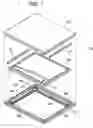
BRIEF DESCRIPTION OF THE DRAWINGSFIG. 1 is an exploded perspective view illustrating a display unit of an information apparatus according to an embodiment of the present invention.
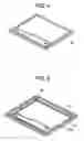
FIG. 2 is a perspective view illustrating the structure of the front cabinet of a display unit of an information apparatus according to an embodiment of the present invention.
FIG. 3 is a perspective view illustrating a structure of the front cabinet of the display unit according to an embodiment of the present invention, with cushions and corner dampers at four corners.
FIG. 4 is a perspective view illustrating a display device according to an embodiment of the present invention.
FIG. 5 is a perspective view illustrating a state of the front cabinet of a display unit according to an embodiment of the present invention, with a display device placed.
FIG. 6 is a perspective view illustrating a state of the front cabinet of a display unit according to an embodiment of the present invention, with dampers.
FIG. 7 is a perspective view illustrating the rear cabinet of the display unit according to an embodiment of the present invention.
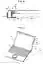
FIG. 8 is a partially sectional view of a state of the display unit with a display device attached.
FIG. 9 is an external perspective view of a notebook-size personal computer according to an embodiment of the present invention.
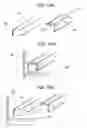
FIGS. 10A, 10B, and 10C are perspective views illustrating a method of assembling a display unit according to an embodiment of the present invention.
DETAILED DESCRIPTIONThe present invention relates to a display unit that utilizes the rigidity of the display device to improve the mechanical strength of the packaging, and that allows reducing the weight of the entire apparatus owing to a reduced part number and simple makeup.
Hereinafter, a description is made for a display unit of an information apparatus according to an embodiment of the present invention, using FIGS. 1 through 10.
FIG. 9 illustrates a makeup of notebook computer 10 equipped with a display unit according to the embodiment. Main body 11 of notebook computer 10 is loaded with keyboard 12, track pad 13, and others. Further, display unit 20 is attached to main body 11 swingably, where additionally a swing can be held at an arbitrary position halfway through the swing, by means of hinge 14. Display unit 20 swings to be lifted from main body 10 so that the operator adjusts it for obtaining suitable viewing angle.
The embodiment is characterized by this makeup of display unit 20. Hereinafter, a description is made using FIGS. 1 through 10. Here, the same element may be given the same mark in FIGS. 1 through 10.
As shown in FIGS. 1 through 10, display unit 20 is a unit in which display device 30 is held between front cabinet 21 and rear cabinet 40. Here, in this embodiment, a description is made using front cabinet 21 and rear cabinet 40 as examples of first case and a second one, respectively. Display device 30 may include a liquid crystal display device, for example. A display device preferably uses a member with high rigidity such as a glass substrate because the rigidity of the display device largely influences that of the display unit of the present invention.
As shown in FIG. 9, front cabinet 21 has large opening 22 on the front surface thereof (at the operator side) so that display surface 31 of display device 30 is visible. Frame part 23 around opening 22 is arranged so as to support only the periphery of display surface 31 of display device 30. As shown in FIG. 8, side wall 24, extending from frame part 23, rises roughly vertically toward rear cabinet 40. Display device 30 is contained within the quadrate framework formed by side wall 24 and placed on frame part 23.
As shown in FIGS. 1, 3, and 8, elongate cushions 25, made of nonwoven fabric for example, may be stuck on the inner surface of frame part 23 of front cabinet 21 with a dual-sided bonding tape or the like, to buffer a touch of frame part 23 on display surface 31 of display device 30 attached. Whether or not to use cushions 25 depends on an application and working conditions of the information apparatus.
Meanwhile, corner dampers 26 made of nonwoven fabric or the like are stuck on the four corners of the inner surface of side wall 24 using a dual-sided bonding tape or the like. Then, display device 30 is attached on the inner side of side wall 24 of front cabinet 21 thus prepared. Corner dampers 26 are used to prevent display device 30 from contacting the side wall directly. Using corner dampers 26 allows preventing fracture and chipping of the edge of a glass substrate used for a liquid crystal display device and the like. The height (heightwise of the side wall) of corner dampers 26 is preferably equal to or greater than the thickness of display device 30. The length (in circumferential direction of the side wall) could be the length enough for protecting the corners of display device 30, preferably equal to or greater than the width of the frame part.
Then as shown in FIG. 8, dual-sided bonding tape 28 is stuck on the surface of support rod 27 at a place where support rod 27 faces side wall 24. Support rod 27 has an elongate and quadrate cross sectional shape. Next, while applying a force in the direction of arrow A and additionally pressing support rod 27 in the direction of arrow B, support rod 27 is fixed to side wall 24 through dual-sided bonding tape 28. Support rod 27 works for fixing display device 30 with keeping pressing against front cabinet 21.
In the process of mounting support rod 27 to side wall 24, jig 50 having reverse L-shape in cross sectional view is preferably used. As shown in FIG. 8, closely fitting the upper right-hand corner of support rod 27, jig 50 is pressed in the direction of arrow A while being pressed in the direction of arrow B. Although it is difficult to press and fix support rod 27 with a roughly uniform force all over support rod 27 if support rod 27 is made of an elastic body or a deformable member, using jig 50 allows the mounting to be performed reliably and easily.
As shown in FIGS. 10A and 10B, needle-shaped projections 51 may be provided on the inner surface of jig 50.
As shown in FIG. 10A, jig 50 having needle-shaped projections 51 is pressed against support rod 27 with dual-sided bonding tape 28 preliminarily stuck thereon. As a result of the pressing, needle-shaped projections 51 dig into the side face of support rod 27, and thus support rod 27 is temporarily held by jig 50. Next, as shown in FIG. 10B, support rod 27 being held by jig 50 is pressed onto a corner formed by display device 30 and side wall 24. At this moment, with support rod 27 keeping pressed in the direction of arrow A through jig 50, support rod 27 is pressed against side wall 24 in the direction of arrow B. As a result, while pressing display device 30 in the direction of arrow A, support rod 27 is fixed to side wall 24 owing to dual-sided bonding tape 28. Then as shown in FIG. 10C, after support rod 27 is fixed to side wall 24, jig 50 is removed. At this moment, traces 29 of needle-shaped projections 51 may remain on the side face of support rod 27 depending on material of support rod 27. As the side face corresponds to the backside of display device 30, traces 29 do not become defects in appearance. As described above, using jig 50 having needle-shaped projections 51 allows jig 50 to be handled integrally with support rod 27, thus remarkably improving the workability and enabling support rod 27 to be reliably fixed.
The number, arrangement, and shape of needle-shaped projections 51 can be selected as appropriate according to the size, weight, and others of support rod 27. Further, instead of using needle-shaped projections 51, an adhesive layer with weak adhesiveness may be coated on the inner surface of jig 50. Alternatively, dual-sided bonding tape with weak adhesivity at least for the surface contacting support rod 27 may be stuck on the inner surface of jig 50. Even in this way, temporary retaining by support rod 27 can be secured. Here, “adhesive layer with weak adhesiveness” means that the adhesive layer has adhesiveness capable of holding the support rod 27 and that the adhesiveness is weaker than the adhesiveness of dual-sided bonding tape 28.
Here, support rod 27 is to be provided on at least two sides facing each other, of side wall 24 as shown in FIG. 1. Support rod 27 may be provided on three sides or on all four sides. Dual-sided bonding tape 28 may be stuck to support rod 27 or side wall 24 preliminarily.
After this, rear cabinet 40 is screwed or fixed by fitting, or the like, to cabinet 21, to complete display unit 20.
Here, support rod 27 is required to fix display device 30 while pressing it with a force as uniform as possible. Further, support rod 27 preferably works as buffer material for protecting display device 30 from an impact in a falling test. As a material of support rod 27, urethane foam with 25% compression stress (JIS K 7220) of 0.33 MPa or more may be suitable. An elastic body made of rubber can be used if its hardness is equal to or higher than 0.33 MPa, although weight reduction may be not remarkable. Besides an elastic body, a rigid body such as synthetic resin or metal may be used for support rod 27, if the falling tests of the information apparatus using such materials are found to cause no problems.
An adhesive may be applied instead of a dual-sided bonding tape used in the present embodiment.
Meanwhile, in this embodiment, side wall 24 is formed in a rib-like shape away from the four sides of front cabinet 21. That is to say, side wall 24 is provided at an inner circumferential side from the outer circumferential edge of the front cabinet by a given distance. However, side wall 24 can be provided at the outer circumferential edge of front cabinet 21.
In addition, cushioning material or an elastic member may be inserted at least one of between rear cabinet 40 and support rod 27, or between rear cabinet 40 and display device 30.
According to the embodiment, as a result that a display device is contained inside the area enclosed by the side wall of the front cabinet, and that the display device is pressed and fixed from above by a support rod made of material with a given hardness, the part number and man-hours can be reduced with a simple makeup. And the cabinet can be resistant to torsion owing to the reinforced cabinet strength utilizing the rigidity of the retained display device even with thin material of the cabinet for weight reduction.
In this embodiment, as shown in FIG. 9, the description is made for an aspect in which display unit 20 is mounted to main body 11. The concept of the present invention may be applied as well to a display unit which can be separated from main body 11.
According to an information apparatus and a method of assembling the information apparatus, of the present invention, an information apparatus having a display device, such as a notebook computer or personal digital assistance, can be manufactured at a low cost and with reduced weight, offering high industrial applicability.
It will be obvious to those skilled in the art that various changes may be made in the above-described embodiment of the present invention. However, the scope on the present invention should be determined by the following claims.
Claims
What is claimed is:1. A display unit comprising:
a display device;
a first case that has an opening and covers a front surface of the display device; and
a second case that covers a back surface of the display device, wherein the first case includes:
a frame part enclosing the opening; and
a side wall orthogonally extending from the frame part toward the second case over an entire circumference of the frame part, wherein the display device is enclosed by the side wall and placed on the frame part,
and wherein at least two support rods are fixed to the side wall and press the display device.
2. The display unit of claim 1, wherein the side wall is provided at an inner circumferential side from an outer circumferential edge of the first case.
3. The display unit of claim 1, wherein the display device has a quadrate outer shape, and wherein at least two of the support rods are disposed on two sides, facing each other, of the display device.
4. The display unit of claim 1, wherein the support rod is an elastic body with 25% compression stress of 0.33 MPa or more.
5. The display unit of claim 1, further comprising a corner damper at a corner of the side wall and at a position where the side wall faces a side face of the display device.
6. The display unit of claim 1, further comprising a cushion between the frame part and the display device.
7. An information apparatus having a main body and a display unit, the display unit comprising:
a first case having an opening, a frame part enclosing the opening and a side wall orthogonally extending from the frame part toward the second case over an entire circumference of the frame part;
a display device placed on the frame part and enclosed by the side wall;
at least two support rods fixed to the side wall and pressing the display device; and
a second case covering the display device.
8. The information apparatus of claim 7, wherein the side wall is provided at an inner circumferential side from an outer circumferential edge of the first case.
9. The information apparatus of claim 7, wherein the display unit includes:
a corner damper at a corner of the side wall and at a position where the side wall faces a side face of the display device; and
a cushion between the frame part and the display device.
10. A method of assembling a display unit including a display device, a first case having a frame part formed with an opening for exposing a front surface of the display device, and a second case covering a back surface of the display device, the method comprising:
a first step for placing the display device in the first case having a side wall orthogonally extending from the frame part toward the second case over an entire circumference of the frame part;
a second step for fixing the display device which is placed on the frame part and at an inner circumferential side of the side wall to the first case, by using at least two of the support rods contacting the display device and the side wall; and
a third step for fixing the second case to the first case, wherein the second step includes:
fixing the support rods to the side wall; and
pressing the support rods toward the display device during the fixing step.
11. The method of assembling a display unit of claim 10, wherein the second process includes an operation in which a jig reverse L-shaped in cross section is fitted to the support rod, and the support rod is pressed toward the display device and simultaneously pressed against the side wall through the jig.
Images & Drawings included:


Sources:
- United States Patent and Trademark Office - verify current appl. status at the USPTO↗
Recent applications in this class:
- » 20250271895 2025-08-28
FOLDABLE ELECTRONIC DEVICE INCLUDING DISPLAY - » 20250264909 2025-08-21
DISPLAY DEVICE - » 20250251755 2025-08-07
DISPLAY DEVICE - » 20250208651 2025-06-26
FOLDABLE COMPUTING DEVICE - » 20250208650 2025-06-26
Display Device - » 20250208649 2025-06-26
Computing Device - » 20250208648 2025-06-26
Computing Device - » 20250199571 2025-06-19
FOLDABLE DISPLAY DEVICE - » 20250199570 2025-06-19
HINGE LOCK APPARATUS FOR ELECTRONIC DEVICES AND RELATED METHODS - » 20250190014 2025-06-12
Bezel-Less Display Mounts
Recent applications for this Assignee:
- » 20250038213 2025-01-30
SLURRY FOR NON-AQUEOUS ELECTROLYTE SECONDARY CELL, METHOD FOR MANUFACTURING SLURRY FOR NON-AQUEOUS ELECTROLYTE SECONDARY CELL, ELECTRODE FOR NON-AQUEOUS ELECTROLYTE SECONDARY CELL, AND NON-AQUEOUS ELECTROLYTE SECONDARY CELL - » 20230388751 2023-11-30
Information providing method and information providing apparatus - » 20230187624 2023-06-15
Positive electrode active material for lithium ion secondary battery and lithium ion secondary battery - » 20220368162 2022-11-17
POWER TRANSMISSION COIL, POWER TRANSMISSION DEVICE, AND UNDERWATER POWER SUPPLY SYSTEMS - » 20220345978 2022-10-27
NETWORK CONTROL DEVICE, NETWORK CONTROL SYSTEM, AND NETWORK CONTROL METHOD - » 20220345847 2022-10-27
Information collecting method, communication control apparatus, and information collector apparatus - » 20220317284 2022-10-06
SURVEILLANCE SYSTEM, AND SURVEILLANCE METHOD - » 20220299596 2022-09-22
MONITORING DEVICE AND MONITORING METHOD - » 20220278402 2022-09-01
RECTANGULAR SECONDARY BATTERY - » 20220205908 2022-06-30
Cellulose composite determination method and apparatus for composite resin