Automatic vehicle collision avoidance and warning system
US20060244632A1
2006-11-02
10/908,214
2005-05-02
✅ Patent granted
US 7,209,050 B2
2007-04-24
-
-
Benjamin C. Lee | Jennifer Mehmood
2025-11-11
Abstract:
An integrated system for automatic vehicle collision avoidance and warning for vehicles operating on any highway or road system globally. The system may be used to not only illuminate the brake lights on the following vehicle but also to begin the application of braking pressure as a result of analysis of the speed of the vehicle. The system includes an RFID transponder (either active or passive) located in the rear and front of the vehicle with discrete recognition capability as to vehicle proximity and resulting action to be taken as a result of driver action. On the vehicle either the brake lights will be illuminated ahead of any actual driver action; an initial application of brake pressure as a result of receiving a signal from the vehicle in front, the pressure which is determined by analysis of the current speed of the vehicle or the system will provide additional warning through brake light illumination to the following vehicle with similar equipment and cruise control will be disengaged. The system can be retrofitted into existing vehicles to provide, at a minimum, brake light illumination indicating an action being taken somewhere ahead of your vehicle. The system thereby warns and prevents serious rear-end collisions at highway speeds especially where vehicle size mismatch contributes to the inability of the following driver to see activity in front of the car in front of him.
Inventors:
- James John Corcoran 2 🇺🇸 Scottsdale, AZ, United States
- James John Corcoran, III 3 🇺🇸 Scottsdale, AZ, United States
Assignee:
- Mr. James John Corcoran 1 🇺🇸 Scottsdale, AZ, United States
Interested in similar patents?
Get notified when new applications in this technology area are published.
Classification:
G06F17/10 IPC
Digital computing or data processing equipment or methods, specially adapted for specific functions Complex mathematical operations
G06G7/78 IPC
Devices in which the computing operation is performed by varying electric or magnetic quantities; Analogue computers for specific processes, systems or devices, e.g. simulators for direction-finding, locating, distance or velocity measuring, or navigation systems
B60Q1/00 IPC
Arrangement of optical signalling or lighting devices, the mounting or supporting thereof or circuits therefor
G08B13/14 IPC
Burglar, theft or intruder alarms; Mechanical actuation by lifting or attempted removal of hand-portable articles
G08G1/16 IPC
Traffic control systems for road vehicles Anti-collision systems
B60Q1/44 » CPC main
Arrangement of optical signalling or lighting devices, the mounting or supporting thereof or circuits therefor the devices being primarily intended to indicate the vehicle, or parts thereof, or to give signals, to other traffic for indicating braking action or preparation for braking, e.g. by detection of the foot approaching the brake pedal
B60Q1/525 » CPC further
Arrangement of optical signalling or lighting devices, the mounting or supporting thereof or circuits therefor the devices being primarily intended to indicate the vehicle, or parts thereof, or to give signals, to other traffic for indicating other intentions or conditions, e.g. request for waiting or overtaking automatically indicating risk of collision between vehicles in traffic or with pedestrians, e.g. after risk assessment using the vehicle sensor data
B60T7/22 » CPC further
Brake-action initiating means for automatic initiation; for initiation not subject to will of driver or passenger initiated by contact of vehicle, e.g. bumper, with an external object, e.g. another vehicle, or by means of contactless obstacle detectors mounted on the vehicle
G08G1/162 » CPC further
Traffic control systems for road vehicles; Anti-collision systems; Decentralised systems, e.g. inter-vehicle communication event-triggered
B60W30/09 » CPC further
Purposes of road vehicle drive control systems not related to the control of a particular sub-unit, e.g. of systems using conjoint control of vehicle sub-units, or advanced driver assistance systems for ensuring comfort, stability and safety or drive control systems for propelling or retarding the vehicle predicting or avoiding probable or impending collision Taking automatic action to avoid collision, e.g. braking and steering
B60W30/143 » CPC further
Purposes of road vehicle drive control systems not related to the control of a particular sub-unit, e.g. of systems using conjoint control of vehicle sub-units, or advanced driver assistance systems for ensuring comfort, stability and safety or drive control systems for propelling or retarding the vehicle cruise control Adaptive Speed control
B60W2556/65 » CPC further
Input parameters relating to data; External transmission of data to or from the vehicle Data transmitted between vehicles
B60W2710/18 » CPC further
Output or target parameters relating to a particular sub-units Braking system
B60W2754/10 » CPC further
Output or target parameters relating to objects Spatial relation or speed relative to objects
G08G1/00 IPC
Traffic control systems for road vehicles
Description
DESCRIPTIONOver the years vehicles have become larger and highways have become more crowded. In an effort to combat the higher incidents of rear-end collisions, various education campaigns have been undertaken by the Federal Highway Administration. An example is one car length per ten miles per hour of speed rule-of-thumb to avoid rear-ending another vehicle. In a review of the IVHS (Intelligent Vehicle Highway System) model of the future, vehicles will have the potential to control more of their actions on the highway without driver intervention or action. On-board processors have become a reality in the vehicles of today. With the advent of ABS (Anti-skid braking systems), vehicles have taken the first step toward processor assisted braking control for the driver of today.
As mentioned, size differences between trucks, automobiles and between automobiles of various classes is a problem pointed out in the investigation of rear-end collisions. The driver of an average size automobile has a problem with seeing what is happening in front of the vehicle in front of him. This is made even worse through the use of extensive window tinting. Early warning of an impending braking action is either limited severely or gone altogether. This system, AVCAWS (Automatic Vehicle Collision Avoidance and Warning System), will provide a phased approach to eliminating or mitigating this problem on the modern highways and assist in the control of traffic in the highways of the future.
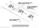
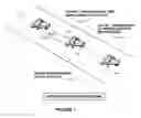
In the basic embodiment of this invention (FIG. 1), System Operation, car No. 1 begins the process by applying the brakes (100). As the brakes are being applied in car No. 1, an on-board active RFID (radio frequency identification system) located in the rear tail light assembly, is transmitting a signal (110) that is received by the active transponder RFID located in the headlight assembly on car No. 2 (125). Car No. 2's brake lights are automatically illuminated (115). Car No. 3's (135) driver begins to actually apply the brakes (120) thereby taking action ahead of the actual visual slowing of car No. 2 (130). This series of events prevents a total surprise to the driver of car No. 3 since the brake lights of car No. 1 are not visible to the driver of car No. 3 due to the size and the height mismatch of the class of vehicles. Active RFID power limitation and discrete recognition frequency and code prevents false signal representation across multiple lanes of traffic.
In the IVHS of the future, another enhanced embodiment is that the processor in car No. 2 (130) would look at the speed of the vehicle and begin to apply the brakes automatically before the driver could take action. The same event would take place in car No. 3 (135) through a similar active RFID transmitting to car No. 3 and the brakes would be applied as a result of analyzing the current speed and when the driver finally reacts to the brake lights illuminating on car No. 2 the driver would continue the brake application from the current applied brake pressure as already applied by the automatic system. This would also disengage the cruise control system as well.
We therefore have a system that takes both pre-emptive action and also provides a signal that requires a driver to take physical action as well. It is an invention that would be capable of not only saving lives in the initial embodiment but also provide a tool to be retrofitted into existing vehicles during routine maintenance visits.
This invention could apply to not only automobiles but trucks and other typical over-the-road vehicles operated around the globe.
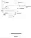
A detailed block diagram, FIG. 2, shows how AVCAWS would be connected on the vehicle. Active RFID receive (200) in the head light assembly, would send a signal to the on-board processor (202). The processor would send a signal to the tail light wiring module (204) to illuminate the rear tail lights (205) and also activate the active RFID located in the rear tail light assembly (203). In the enhanced embodiment, the on-board processor (202) would take additional input from the speed sensor (206) and a signal would be sent to the ABS (anti-skid braking system) (207) and it would apply the brakes automatically (208) and disconnect the cruise control, if engaged, at that time.
Detailed description of the preferred embodiment is provided herein. It is to be understood, however, that the present invention may be embodied in various forms. Therefore, specific details disclosed herein are not to be interpreted as limiting, but rather as a basis for the claims and as a representative basis for teaching one skilled in the art how to employ the present invention in an appropriately detailed system, structure or manner.
In the foregoing specification, the invention has been described with reference to specific embodiments. However, one of ordinary skill in the art appreciates that various modifications and changes can be made without departing from the scope of the present invention as set forth in the claims below. Accordingly, the specification and figures are to be regarded in an illustrative rather than a restrictive sense and all such modifications are intended to be included within the scope of the present invention.
In addition, benefits, other advantages, and solutions to problems, and any element(s) what may cause any benefit, advantage, or solution to occur or become more pronounced are not to be construed as critical, required, or essential feature or element of any or all the claims. As used herein, the terms “comprises,” “comprising” or any other variation thereof are intended to cover non-exclusive inclusion, such that a process, method, article, or apparatus that comprises a list of elements does not include only those elements but may include other elements not expressly listed or inherent to such process, method, article, or apparatus.
While the invention has been described in connection with a preferred embodiment, it is not intended to limit the scope of the invention to the particular form set forth, but on the contrary, it is intended to cover such alternatives, modifications, and equivalents as may be included within the spirit and scope of the invention as defined by the appended claims.
Claims
What is claimed is:1. A totally integrated system for automatic vehicle collision avoidance and warning system for vehicles, said system comprising:
an automatic vehicle collision avoidance and warning system having a RFID transponder located on the vehicle to enable communications to another vehicle with similar equipment installed,
an RFID transponder located on the vehicle that provides a communication signal to another vehicle with similar equipment,
an RFID transponder located on the vehicle that provides a communication signal indicating a braking action being taken by a vehicle,
an RFID transponder that has links into the braking system of the vehicle and provides an indication of braking activity through a signal to another vehicle with similar equipment,
an RFID transponder on a similar vehicle that is linked to the braking system that provides a signal to illuminate the brake lights on the receiving vehicle,
an RFID device that can be either active or passive,
a means for sending an RFID signal to another vehicle with similar equipment and that vehicle being able to receive it and take action through the illumination of the brake lights on the receiving vehicle,
a means for linking to an existing brake system in order to analyze the speed and have the anti-skid braking system apply the brakes prior to the driver taking action and disconnect the cruise control,
a means to link into an existing brake light system on the vehicle,
a means to allow the driver of the vehicle to apply brake pressure from the existing pressure application initially applied by the signal and analysis of the AVCAWS system,
a means to distinguish the difference through either discrete frequency or identification as to whether the vehicle is following or providing the lead signal for the purposes of braking and brake light illumination.
2. A process for automatic vehicle collision avoidance and warning system comprising a RFID transponder system located on the vehicle that links with the ABS system, the speedometer system and the cruise control system, said system allows the illumination of the brake lighting system ahead of the taking of driver action on vehicles that are following another during highway traffic patterns,
linking to the braking system of the vehicle including the brake lights and the speedometer system,
providing an early warning brake light to a following vehicle equipped with similar equipment enabling the following driver to be aware of impending braking activity on the lead vehicle,
providing a linkage to the ABS on the vehicle in order to begin early application of brake pressure to prevent rear-end collisions,
providing a linkage to the speedometer processor on the vehicle in order to compute the amount of brake pressure to be applied as a result of receiving a signal from the RFID transponder on the vehicle in front of the receiving vehicle,
providing a discrete RFID signal, either active or passive, that generates a signal for the on-board processor and wiring module,
providing a combination of both braking pressure and brake light illumination to the following vehicle equipped with similar RFID AVCAWS installation.
Images & Drawings included:
Sources:
- United States Patent and Trademark Office - verify current appl. status at the USPTO↗
Recent applications in this class:
- » 20250289363 2025-09-18
TANKER TRUCK WITH REAR LIGHTING ASSEMBLY AND METHOD OF OPERATION - » 20250256640 2025-08-14
TRAILER SYSTEM AND METHOD FOR MODULATING SIGNALS FROM A VEHICLE TO A TRAILER - » 20240416828 2024-12-19
CONSTRUCTION MACHINE - » 20240391379 2024-11-28
SYSTEMS AND METHODS FOR VIRTUAL CONNECTION-BASED BRAKE LIGHT CONTROL - » 20240286544 2024-08-29
Truck box light controller - » 20240010121 2024-01-11
BRAKE APPLICATION DETECTION - » 20220281380 2022-09-08
Brake light for truck bed enclosure - » 20220258664 2022-08-18
INTELLIGENT REAR-END COLLISION PREVENTING DYNAMIC COLOR-CHANGING BRAKE LIGHT FOR AUTOMOBILE - » 20220097600 2022-03-31
Vehicle brake light control during one-pedal drive - » 20210394671 2021-12-23
Early brake light warning system for autonomous driving vehicle