Device, system and method for realizing on screen display
US20060244763A1
2006-11-02
11/323,268
2005-12-30
✅ Patent granted
US 7,663,646 B2
2010-02-16
-
-
M Good Johnson
2026-03-22
Abstract:
A device for realizing on screen display (OSD) translucency in video signals includes a comparator (430) and an outputting control unit (440). The comparator (430) is used for receiving OSD signals and identification signals on a background color selected to be transparent in the OSD signals, identifying the background color in the OSD signals based on the identification signals, and generating a control signal based on the identification. The outputting control unit (440) is connected to the comparator (430), and is used for receiving UV components of the OSD signals, UV components of the video signals, and the control signal, and for selectively outputting UV data of the video signals or UV data of the OSD signals according to the control signal. By employing the device, OSD translucency can be efficiently realized through simple operations. A related system and method for efficiently realizing OSD translucency are also provided.
Assignee:
- HON HAI Precision Industry CO., LTD. 1,310 🇹🇼 Tu-Cheng City, Taiwan
- HON HAI PRECISION INDUSTRY CO., LTD. 2,357 🇹🇼 Tu-Cheng, Taipei Hsien, Taiwan
Interested in similar patents?
Get notified when new applications in this technology area are published.
Classification:
G09G5/026 » CPC main
Control arrangements or circuits for visual indicators common to cathode-ray tube indicators and other visual indicators characterised by the way in which colour is displayed Control of mixing and/or overlay of colours in general
H04N5/44504 » CPC further
Details of television systems; Receiver circuitry for the reception of television signals according to analogue transmission standards for displaying additional information Circuit details of the additional information generator, e.g. details of the character or graphics signal generator, overlay mixing circuits
H04N9/76 » CPC further
Details of colour television systems; Circuits for processing colour signals for obtaining special effects for mixing of colour signals
H04N21/4318 » CPC further
Selective content distribution, e.g. interactive television or video on demand [VOD]; Client devices specifically adapted for the reception of or interaction with content, e.g. set-top-box [STB]; Operations thereof; Processing of content or additional data, e.g. demultiplexing additional data from a digital video stream; Elementary client operations, e.g. monitoring of home network or synchronising decoder's clock; Client middleware; Generation of visual interfaces for content selection or interaction ; Content or additional data rendering by altering the content in the rendering process, e.g. blanking, blurring or masking an image region
H04N21/4355 » CPC further
Selective content distribution, e.g. interactive television or video on demand [VOD]; Client devices specifically adapted for the reception of or interaction with content, e.g. set-top-box [STB]; Operations thereof; Processing of content or additional data, e.g. demultiplexing additional data from a digital video stream; Elementary client operations, e.g. monitoring of home network or synchronising decoder's clock; Client middleware; Processing of additional data, e.g. decrypting of additional data, reconstructing software from modules extracted from the transport stream involving reformatting operations of additional data, e.g. HTML pages on a television screen
H04N21/44004 » CPC further
Selective content distribution, e.g. interactive television or video on demand [VOD]; Client devices specifically adapted for the reception of or interaction with content, e.g. set-top-box [STB]; Operations thereof; Processing of content or additional data, e.g. demultiplexing additional data from a digital video stream; Elementary client operations, e.g. monitoring of home network or synchronising decoder's clock; Client middleware; Processing of video elementary streams, e.g. splicing a video clip retrieved from local storage with an incoming video stream, rendering scenes according to MPEG-4 scene graphs involving video buffer management, e.g. video decoder buffer or video display buffer
G09G5/00 IPC
Control arrangements or circuits for visual indicators common to cathode-ray tube indicators and other visual indicators
H04N5/50 IPC
Details of television systems; Receiver circuitry for the reception of television signals according to analogue transmission standards Tuning indicators; Automatic tuning control
Description
BACKGROUND OF THE INVENTION1. Field of the Invention
The present invention relates to devices, systems and methods for processing images, and particularly to a device, system and method for realizing on screen display (OSD) translucency.
2. Related Art
On screen display (OSD) technology is widely used in image processing devices such as TVs (televisions), PCs (personal computers), and mobile terminals. The OSD displays additional information such as a channel selection and display time of the image processing device.
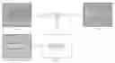
However, conventional OSD techniques have a shortcoming in that the OSD partially covers images being shown on the screen of the image processing device. Referring to FIG. 5, image (e) schematically illustrates an original image of an image processing device, and image (f) schematically illustrates an OSD image. Image (g) shows the OSD image without a background color. When the OSD image and the original image are combined as shown in image (h), the OSD image partially covers the original image, which can significantly mar the appearance of the original image.
If the OSD image is made translucent, the above-described problem is readily solved. Viewers can see both the OSD image and the original image simultaneously.
A typical system and method for realizing OSD translucency generally adopts alpha blending theory that complies with the RGB (red green blue) standard. The alpha blending theory is a process of combining a foreground RGB color with a background RGB color, and then producing a new blended RGB color. That is, RGB data of the OSD signals and RGB data of the video signals are alpha blended to realize the OSD translucency. Formulas that describe the alpha blending theory are as follows:
{
Blended
-
red
=
Foreground
-
red
*
alpha
+
Background
-
red
*
(
1
-
alpha
)
Blended
-
green
=
Foreground
-
green
*
alpha
+
Background
-
green
*
(
1
-
alpha
)
Blended
-
blue
=
Foreground
-
blue
*
alpha
+
Background
-
blue
*
(
1
-
alpha
)
wherein alpha is a parameter, and alpha values are in the range from 0 to 1; the RGB data of the OSD signals are respectively represented as foreground-red, foreground-green, and foreground-blue; and the RGB data of the video signals are respectively represented as background-red, background-green, and background-blue. Different translucency effects are realized by selecting different alpha values. However, the alpha blending process needs a multiplication device with a complicated operation.
Further, for many image processing devices, image signals are generally processed or transmitted based on the YUV standard. The YUV (YCrCb) standard is a color encoding standard that is used worldwide as a television broadcasting standard. Y signals stand for a luminance component. U signals and V signals stand for chrominance components. One advantage of the YUV standard is that signals can be easily manipulated to selectively discard some information and thereby reduce transmission bandwidth. However, the above-described conventional method for realizing OSD translucency adopts the alpha blending theory, which is based on the RGB standard. Therefore, in order to utilize the OSD translucency method, video signals and OSD signals that comply with the YUV standard must be changed to signals that comply with the RGB standard. The change can result in image display error.
Therefore, a heretofore unaddressed need exists in the industry to overcome the aforementioned deficiencies and inadequacies.
SUMMARYA device for realizing OSD translucency in video signals according to an exemplary embodiment of the present invention includes a comparator and an output control unit. The comparator is used for receiving OSD signals and identification signals on a background color selected to be transparent in the OSD signals, identifying the background color in the OSD signals based on the identification signals, and generating a control signal based on the identification. The output control unit is connected to the comparator. The output control unit is used for receiving UV components of the OSD signals, UV components of the video signals, and the control signal, and for selectively outputting UV data of the video signals or UV data of the OSD signals according to the control signal. If the background color in the OSD signals is the same as the identification signals, the UV data of the video signals instead of the corresponding UV data of the OSD signals are output; and if the background color in the OSD signals is different from the identification signals, the UV data of the OSD signals are output.
A system for realizing OSD translucency in video signals according to an exemplary embodiment of the present invention includes a video signal receiver, an OSD signal receiver, an OSD transparent identification unit, a comparator, and an output control unit. The video signal receiver is used for receiving the video signals. The OSD signal receiver is used for receiving OSD signals. The OSD transparent identification unit is used for receiving identification signals on a background color selected to be transparent in the OSD signals. The comparator is connected to the OSD signal receiver and the OSD transparent identification unit. The comparator is used for receiving the OSD signals and the identification signals, identifying the background color in the OSD signals based on the identification signals, and generating a control signal based on the identification. The output control unit is connected to the video signal receiver, the OSD signal receiver and the comparator. The output control unit is used for receiving UV components of the OSD signals, UV components of the video signals, and the control signal, and for selectively outputting UV data of the video signals or UV data of the OSD signals according to the control signal. If the background color in the OSD signals is the same as the identification signals, the UV data of the video signals instead of the corresponding UV data of the OSD signals are output; and if the background color in the OSD signals is different from the identification signals, the UV data of the OSD signals are output.
A method for realizing OSD translucency in video signals according to an exemplary embodiment of the present invention includes the steps of: receiving video signals and OSD signals; receiving identification signals on a background color selected to be transparent in the OSD signals; identifying the background color in the OSD signals based on the identification signals; and outputting UV data of the video signals instead of corresponding UV data of the OSD signals if the background color in the OSD signals is the same as the identification signals; or outputting UV data of the OSD signals if the background color in the OSD signals is different from the identification signals.
By employing the above-described device, system and method, OSD translucency in video signals can be efficiently realized through simple operations.
Other advantages and novel features will be drawn from the following detailed description when considered with the attached drawings, in which:
BRIEF DESCRIPTION OF THE DRAWINGSFIG. 1 is a block diagram of a system for realizing OSD translucency in video signals according to an exemplary embodiment of the present invention;
FIG. 2 is a block diagram of a system for realizing OSD translucency in video signals according to another exemplary embodiment of the present invention.
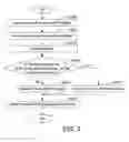
FIG. 3 is a flow chart of a method for realizing OSD translucency in video signals according to still another exemplary embodiment of the present invention;
FIG. 4 schematically illustrates an exemplary image display and precursors thereof when an OSD translucency function is implemented according to any of the exemplary embodiments of the present invention; and
FIG. 5 schematically illustrates an exemplary image display and precursors thereof when OSD signals are blended with video signals according to conventional techniques.
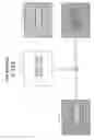
DETAILED DESCRIPTION OF PREFERRED EMBODIMENTSFIG. 1 shows a block diagram of a system for realizing OSD translucency according to an exemplary embodiment of the present invention. In the exemplary embodiment, the system includes a video signal receiver 100, an OSD signal receiver 200, an OSD transparent identification unit 300, an OSD translucency-realizing device 400, and a display 500. The OSD translucency-realizing device 400 includes a buffer unit 410, a register 420, a comparator 430, and an output control unit 440. In the exemplary embodiment, the buffer unit 410 includes a first buffer 412, a second buffer 414, and a third buffer 416.
The video signal receiver 100 is used for receiving video signals Y1U1V1, and for outputting the Y1U1V1 signals to the buffer unit 410. The Y1 component of the Y1U1V1 signals is transmitted to the first buffer 412, and the U1V1 components of the Y1U1V1 signals are transmitted to the second buffer 414. The OSD signal receiver 200 is used for receiving OSD signals. In the exemplary embodiment, the OSD signals are Y2U2V2 signals. The OSD signal receiver 200 outputs the Y2U2V2 signals to the OSD translucency-realizing device 400. In particular, the U2V2 components of the Y2U2V2 signals are transmitted to the third buffer 416, and the Y2U2V2 signals are transmitted to the comparator 430. In the exemplary embodiment, signals received by the video signal receiver 100 and the OSD receiver 200 are all compliant with the YUV standard. Referring to FIG. 2, in another embodiment, if signals received by the OSD receiver 200 are not compliant with the YUV standard but instead compliant with the RGB standard, a signal converter 210 in the OSD signal receiver 200 is provided for converting the RGB standard signals R2G2B2 to YUV standard signals Y2U2V2. An operation formula for converting RGB data to YUV data is as follows: { V = ( 0.439 * R ) - ( 0.368 * G ) - ( 0.071 * B ) + 128 U = - ( 0.148 * R ) - ( 0.291 * G ) + ( 0.493 * B ) + 128
In the exemplary embodiment, the OSD transparent identification unit 300 is used for receiving identification signals Y3U3V3 on a background color selected to be transparent in the OSD signals Y2U2V2. That is, the OSD signals Y2U2V2 have identification signals Y3U3V3 that are to be transparent. The register 420 is connected to the OSD transparent identification unit 300, and is used for storing the identification signals Y3U3V3. The comparator 430 is connected to the OSD signal receiver 200 and the register 420. The comparator 430 is used for receiving the OSD signals Y2U2V2 and the identification signals Y3U3V3, for identifying the background color in the OSD signals Y2U2V2 based on the corresponding identification signals Y3U3V3, and for generating and outputting a control signal based on the identification. The first buffer 412 is connected between the video signal receiver 100 and the display 500, and is used for storing Y1 data of the video signals Y1U1V1. The second buffer 414 is connected between the video signal receiver 100 and the output control unit 440, and is used for storing U1V1 data of the video signals Y1U1V1. The third buffer 416 is connected between the OSD signal receiver 200 and the output control unit 440, and is used for storing U2V2 data of the OSD signals Y2U2V2. The output control unit 440 is also connected to the comparator 430. The output control unit 440 is used for receiving the control signal, and for selectively outputting the U1V1 data of the video signals Y1U1V1 or the U2V2 data of the OSD signals Y2U2V2 according to the control signal. In the exemplary embodiment, if the background color in the OSD signals Y2U2V2 is same as the identification signals Y3U3V3, the output control unit 440 outputs the U1V1 data of the video signals Y1U1V1 instead of the corresponding U2V2 data of the OSD signals Y2U2V2; and if the background color in the OSD signals Y2U2V2 is different from the identification signals Y3U3V3, the output control unit 440 outputs the U2V2 data of the OSD signals Y2U2V2. The output UV data are designated as U4V4. The display 500 is connected to the first buffer 412 and the output control unit 440, and is used for blending the U4V4 data and the Y1 data of the video signals Y1U1V1, and for displaying blended Y1U4V4 signals.
FIG. 3 is a flow chart of a method for realizing on screen display (OSD) translucency in video signals according to the exemplary embodiment of the present invention. At step S1002, the buffer unit 410 receives video signals and OSD signals. In the exemplary embodiment, the received video signals and the received OSD signals are all compliant with the YUV standard. In another embodiment, if the received OSD signals are compliant with the RGB standard, as shown in FIG. 2, the signal converter 210 in the OSD signal receiver 200 converts the RGB standard OSD signals to YUV standard OSD signals. At step S1004, the OSD transparent identification unit 300 receives identification signals on a background color selected to be transparent in the OSD signals. At step S1006, the identification signals are stored in the register 420, and the register 420 updates the identification signals transmitted from the OSD transparent identification unit 300 immediately. At step S1008, the comparator 430 identifies the background color in the OSD signals, and determines whether the background color in the OSD signals is the same as the identification signals. If the background color in the OSD signals is different from the identification signals, at step S1010, the output control unit 440 outputs the UV data of the OSD signals. If the background color in the OSD signals is the same as the identification signals, at step S1012, the output control unit 440 outputs the UV data of the video signals. At the last step S1014, the display 500 blends the Y data of the video signals and the UV data transmitted from the output control unit 440, and displays the blended YUV signals.
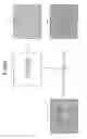
FIG. 4 schematically illustrates an exemplary image display and precursors thereof when an OSD translucency function is implemented according to any of the above-described exemplary embodiments of the present invention. Inage (a) schematically illustrates a video image which is formed with video signals, and image (b) schematically illustrates an OSD image which is formed with OSD signals. At first, the OSD signals of the OSD image are processed by the comparator 430. Y data of the OSD signals and the background color in the OSD signals that is same as the identification signals are eliminated, as shown in image (c). Subsequently, the Y data of the video signals and the UV data selected by the output control unit 440 are blended and displayed, as shown in image (d).
Although only exemplary embodiments have been described in detail above, those skilled in the art will readily appreciate that many modifications to the exemplary embodiments are possible without materially departing from the novel teachings and advantages of the present invention. Accordingly, all such modifications are deemed to be covered by the following claims and allowable equivalents of the claims.
Claims
I claim:1. A method for performing translucency of an on-screen display (OSD) along with video signals on a display, comprising the steps of:
retrieving a first presenting part of video signals to be viewable on a display;
retrieving a second presenting part of said video signals other than said first part;
retrieving a second presenting part of on-screen-display (OSD) signals corresponding to said second part of said video signals;
generating control signals related to removal of a background part of said OSD signals;
selectively transmitting said retrieved second part of said video signals and said retrieved second part of said OSD signals for display according to said control signals; and
displaying combinative viewable signals on said display by means of blending said retrieved first part of said video signals and said selectively-transmitted second part of one of said video signals and said OSD signals.
2. The method as recited in claim 1, wherein said video signals and OSD signals are presented under a YUV standard, said first part is a Y component of presentation under said YUV standard, and said second part is a UV component of said presentation under said YUV standard.
3. The method as recited in claim 1, wherein said retrieved first part of said video signals, said retrieved second part of said video signals and said retrieved second part of said OSD signals are stored in different buffers before further processing.
4. The method as recited in claim 1, further comprising the step of retrieving identification signals to be comparable with said OSD signals.
5. The method as recited in claim 4, wherein said background part of said OSD signals is removed based on a comparative result of said OSD signals and said identification signals.
6. The method as recited in claim 2, further comprising the step of converting available OSD signals presented under a RGB (red green blue) standard to said OSD signals presented under said YUV standard.
7. A system for realizing on screen display (OSD) translucency in video signals, comprising:
a video signal receiver for receiving video signals;
an OSD signal receiver for receiving OSD signals;
an OSD transparent identification unit for receiving identification signals on a background color selected to be transparent in the OSD signals;
a comparator connected to the OSD signal receiver and the OSD transparent identification unit for receiving the OSD signals and the identification signals, identifying the background color in the OSD signals based on the identification signals, and generating a control signal based on the identification; and
an output control unit connected to the video signal receiver, the OSD signal receiver, and the comparator, for receiving UV components of the OSD signals, UV components of the video signals, and the control signal, and for selectively outputting UV data of the video signals or UV data of the OSD signals according to the control signal;
wherein if the background color in the OSD signals is the same as the identification signals, the UV data of the video signals instead of the corresponding UV data of the OSD signals are output; and if the background color in the OSD signals is different from the identification signals, the UV data of the OSD signals are output.
8. The system as recited in claim 7, further comprising a display connected to the video signal receiver and the output control unit for blending Y data of the video signals and the UV data transmitted from the output control unit, and for displaying blended YUV signals.
9. The system as recited in claim 8, further comprising a buffer connected between the video signal receiver and the display for storing the Y data of the video signals.
10. The system as recited in claim 7, wherein the OSD signal receiver comprises a signal converter for converting received RGB (red green blue) signals of the OSD signals to YUV signals.
11. The system as recited in claim 7, further comprising a buffer connected between the video signal receiver and the output control unit for storing the UV data of the video signals.
12. The system as recited in claim 7, further comprising a buffer connected between the OSD signal receiver and the output control unit for storing the UV data of the OSD signals.
13. The system as recited in claim 7, further comprising a register connected between the OSD transparent identification unit and the comparator for storing the identification signals.
14. A method for realizing on screen display (OSD) translucency in video signals, the method comprising the steps of:
receiving video signals and OSD signals;
receiving identification signals on a background color selected to be transparent in the OSD signals;
identifying the background color in the OSD signals based on the identification signals; and
outputting UV data of the video signals instead of corresponding UV data of the OSD signals, if the background color in the OSD signals is the same as the identification signals; or
outputting UV data of the OSD signals, if the background color in the OSD signals is different from the identification signals.
15. The method as recited in claim 14, wherein the step of receiving video signals and OSD signals comprises the steps of:
determining whether the OSD signals are compliant with the YUV standard; and
outputting the OSD signals if the OSD signals are compliant with the YUV standard.
16. The method as recited in claim 15, wherein the step of receiving video signals and OSD signals further comprises the step of:
converting RGB (red green blue) signals of the OSD signals into YUV signals and outputting the YUV signals, if the OSD signals are compliant with the RGB standard.
17. The method as recited in claim 14, further comprising the step of:
blending Y data of the video signals and the output UV data, and displaying blended YUV signals.
Images & Drawings included:


Sources:
- United States Patent and Trademark Office - verify current appl. status at the USPTO↗
Recent applications in this class:
- » 20250266014 2025-08-21
SUBTRACTIVE COLOR CHANGE SYSTEM AND METHOD - » 20250174211 2025-05-29
MIXING SECONDARY GRAPHICS ELEMENTS IN HDR IMAGES - » 20250131896 2025-04-24
ELECTRONIC DEVICE, DISPLAY CONTROL METHOD, AND STORAGE MEDIUM - » 20250022436 2025-01-16
RENDERING OF FIELD SEQUENTIAL DISPLAYS IN A DISPLAY SUBSYSTEM - » 20240339091 2024-10-10
IMAGE DISPLAY METHOD AND APPARATUS, ELECTRONIC DEVICE, AND STORAGE MEDIUM - » 20240161714 2024-05-16
Subtractive color change system and method - » 20240096298 2024-03-21
DISPLAY DIAGNOSIS DEVICE, DISPLAY DIAGNOSIS METHOD, AND NON-TRANSITORY COMPUTER READABLE MEDIUM - » 20230124739 2023-04-20
Edge illumination architecture for display device - » 20230108938 2023-04-06
Subtractive color change system and method - » 20230103014 2023-03-30
Dynamic frame rate conversion in active matrix display
Recent applications for this Assignee:
- » 20140363586 2014-12-11
Laser-based method for growing an array of carbon nanotubes - » 20140299819 2014-10-09
Method for making a carbon nanotube film - » 20140199855 2014-07-17
Method for making a carbon nanotube film - » 20110171419 2011-07-14
Electronic element having carbon nanotubes - » 20110110535 2011-05-12
Carbon nanotube speaker - » 20110101832 2011-05-05
SECURING MECHANISM AND ELECTRONIC DEVICE ENCLOSURE USING THE SAME - » 20110096516 2011-04-28
SUPPORTING ASSEMBLY FOR PRINTED CIRCUIT BOARD - » 20110096473 2011-04-28
Electronic device - » 20110093746 2011-04-21
System and method for determining display function of BIOS error information - » 20110073276 2011-03-31
Heat dissipation system