Loudspeaker
US20060245615A1
2006-11-02
10/549,424
2005-02-22
✅ Patent granted
US 7,542,583 B2
2009-06-02
WO; PCT/JP2005/002751; 20050222
WO; WO2005/086530; 20050915
Curtis Kuntz | Jesse A Elbin
2026-07-24
Abstract:
A loudspeaker has a configuration in which edge diameter in the cross section of second edge coupled to suspension holder is set to be larger than edge diameter in the cross section of first edge coupled to diaphragm. With such a configuration, a loudspeaker with reduced harmonic distortion is provided.
Assignee:
- PANASONIC CORPORATION 20,737 🇯🇵 Osaka, Japan
Interested in similar patents?
Get notified when new applications in this technology area are published.
Classification:
H04R7/20 IPC
Diaphragms for electromechanical transducers ; Cones; Mounting or tensioning of diaphragms or cones at the periphery Securing diaphragm or cone resiliently to support by flexible material, springs, cords, or strands
H04R7/18 » CPC main
Diaphragms for electromechanical transducers ; Cones; Mounting or tensioning of diaphragms or cones at the periphery
H04R7/26 » CPC further
Diaphragms for electromechanical transducers ; Cones Damping by means acting directly on free portion of diaphragm or cone
H04R9/043 » CPC further
Transducers of moving-coil, moving-strip, or moving-wire type; Details; Construction, mounting, or centering of coil; Centering Inner suspension or damper, e.g. spider
H04R2307/201 » CPC further
Details of diaphragms or cones for electromechanical transducers, their suspension or their manufacture covered by or , not provided for in any of its subgroups Damping aspects of the outer suspension of loudspeaker diaphragms by addition of additional damping means
H04R2307/207 » CPC further
Details of diaphragms or cones for electromechanical transducers, their suspension or their manufacture covered by or , not provided for in any of its subgroups Shape aspects of the outer suspension of loudspeaker diaphragms
H04R2499/13 » CPC further
Aspects covered by or not otherwise provided for in their subgroups; General applications Acoustic transducers and sound field adaptation in vehicles
H04R9/06 IPC
Transducers of moving-coil, moving-strip, or moving-wire type Loudspeakers
H04R1/00 IPC
Details of transducers, loudspeakers or microphones
Description
TECHNICAL FIELDThe present invention relates to a loudspeaker.
BACKGROUND ARTFIG. 5 is a sectional view showing a conventional loudspeaker. As shown in FIG. 5, a conventional loudspeaker has a structure in which voice coil unit 2 that is slidably disposed on magnetic circuit 1 is coupled to the inner circumferential end of diaphragm 3, the outer circumferential end of diaphragm 3 is coupled to frame 5 via first edge 4, and furthermore, the rear surface of diaphragm 3 is coupled to frame 5 via suspension holder 6 and second edge 7. In this structure, since first edge 4 and second edge 7 are symmetric to each other, harmonic distortion of a loudspeaker is reduced and power linearity is improved. Information of prior art document relating to the invention of this application is disclosed in, for example, Japanese Patent Unexamined Publication No. 2004-7335.
In such a loudspeaker, however, the outer diameter of second edge 7 contained in frame 5 is inevitably smaller than that of first edge 4 provided in an open part of frame 5. Therefore, it has been difficult to perfectly equalize the upper and lower amplitudes of diaphragm 3, thus making it difficult to completely suppress the harmonic distortion of a loudspeaker.
SUMMARY OF THE INVENTIONThe object of the present invention is to reduce harmonic distortion further by solving the above-mentioned problem with a prior art.
In order to achieve the above-mentioned object, a loudspeaker of the present invention has a configuration in which the edge diameter in the cross section of a second edge coupled to a suspension holder is set to be larger than the edge diameter in the cross section of a first edge coupled to a diaphragm.
With such a configuration, the difference between the compliance by the second edge and the compliance by the first edge can be excluded, and the harmonic distortion of a loudspeaker can be further reduced.
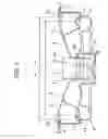
BRIEF DESCRIPTION OF THE DRAWINGSFIG. 1 is a sectional view showing a loudspeaker in accordance with an exemplary embodiment of the present invention.
FIG. 2 is a graph to show the improvement of harmonic distortion factor of a loudspeaker in accordance with an exemplary embodiment of the present invention.
FIG. 3 is a sectional view showing a structure of attachment of a diaphragm in another exemplary embodiment.
FIG. 4 is a sectional view showing a structure of attachment of a diaphragm in a further exemplary embodiment.
FIG. 5 is a sectional view showing a conventional loudspeaker.
REFERENCE MARKS IN THE DRAWINGS
-
- 1 magnetic circuit
- 2 voice coil unit
- 3 diaphragm
- 4 first edge
- 5 frame
- 6 suspension holder
- 7 second edge
- 13 magnetic gap
- 14, 15 edge diameter
Hereinafter, an exemplary embodiment of the present invention is described with reference to drawings. In the description, the same reference numbers refer to the same configurations described above as a background art.
FIG. 1 is a sectional view showing a loudspeaker in accordance with an exemplary embodiment of the present invention. Magnetic circuit 1 disposed in the middle of the bottom part of frame 5 is constructed by combining and adhesively bonding magnet 10, plate 11 and yoke 12. Magnetic circuit 1 is provided with magnetic gap 13 opening toward the upper side of the loudspeaker. Voice coil unit 2 has a structure including cylindrical main body 2a and coil 2b wound around the outer circumferential part of main body 2a and is disposed slidably with respect to magnetic gap 13, in which the sliding allows the amplitude of diaphragm 3. Diaphragm 3 is coupled to the upper part of voice coil unit 2 at its inner circumferential end part and to the opening part of frame 5 at its outer circumferential end part via first edge 4. Furthermore, the bottom surface side of diaphragm 3 is coupled to frame 5 via suspension holder 6 and second edge 7.
In the thus configured loudspeaker, the power point for sliding voice coil unit 2 is allowed to exist inside a region surrounded by first edge 4 and second edge 7, which are coupled to frame 5. Thereby, diaphragm 3, suspension holder 6 and voice coil unit 2 are regarded as one solid body, and therefore, loading of voice coil unit 2 is suppressed. Furthermore, since the bending direction of first edge 4 that supports diaphragm 3 and the bending direction of second edge 7 that supports suspension holder 6 are symmetric to each other, action of canceling the nonlinearity in the respective directions of vibration occurs, thus enabling harmonic components generated in diaphragm 3 to be attenuated.
However, since first edge 4 is coupled to the open end side of frame 5 and attached to the outer circumferential end of diaphragm 3 having a larger outer circumference diameter, and second edge 7 is coupled to the bottom surface side of frame 5 and attached to the outer circumferential end of suspension holder 6 having a smaller outer circumference diameter, the difference in the compliance for supporting the rigid body consisting of diaphragm 3, suspension holder 6 and voice coil unit 2 occurs between in first edge 4 and second edge 7.
Therefore, in the loudspeaker according to the present invention, in order to exclude this difference, edge diameter 14 in the cross section of second edge 7 is set to be larger than edge diameter 15 of first edge 4.
FIG. 2 is a graph to show the improvement of the harmonic distortion factor of a loudspeaker in accordance with an exemplary embodiment of the present invention, which is obtained from experiment results. In FIG. 2, the abscissa shows the voice frequency from the loudspeaker and the ordinate shows the harmonic distortion factor of the loudspeaker.
When the value r1 of edge diameter 15 is equal to the value r2 of edge diameter 14 (r2/r=1), a harmonic distortion factor property as shown by a dashed line in FIG. 2 is obtained. The graph shows that in the low frequency range from 20 Hz to 40 Hz, the harmonic distortion factor of the loudspeaker is more than 10% and the reproducibility of sound is damaged.
When the value r2 of edge diameter 14 is set to be larger than the value r1 of edge diameter 15 (r2/r1=1.5), a harmonic distortion factor property as shown by a solid line in FIG. 2 was obtained. At this time, even in the voice frequency in the range of about 20 Hz, the harmonic distortion factor of the loudspeaker can be suppressed to less than 10%. Furthermore, in the voice frequency range of about 35 Hz or more, the harmonic distortion factor of the loudspeaker can be reduced to as low as less than 5%.
By setting the values as mentioned above, the increase in the compliance of second edge 7 because of outer circumference diameter 9 being small is suppressed. Then, the difference in the compliance between first edge 4 and second edge 7, which couple the rigid body consisting of diaphragm 3, suspension holder 6 and voice coil unit 2 to frame 5, is excluded, and thus the harmonic distortion of the loudspeaker is further reduced. In particular, the harmonic distortion factor in the low frequency range is suppressed and the reproducibility of sound of the loudspeaker is improved.
Furthermore, in the structure shown in FIG. 1, first edge 4 bends downward and second edge 7 bends upward. With this structure, first edge 4 can be prevented from protruding from the upper end side of frame 5, thus downsizing the loudspeaker itself. Although not shown, when first edge 4 bends upward and second edge 7 bends downward, the distance between the fulcrums of first edge 4 seen from diaphragm and the fulcrum of second edge 7 seen from suspension holder 6 is substantially increased, thus enabling the loading of voice coil unit 2 to be suppressed further.
In the configuration shown in FIG. 1, diaphragm 3 is directly coupled to voice coil unit 2. However, as shown in FIG. 3, an inner circumferential part of suspension holder 6 is further extended from a connection point between suspension holder 6 and diaphragm 3, and diaphragm 3 may be indirectly coupled to voice coil unit 2 via this extended part. Furthermore, as shown in FIG. 4, diaphragm 3 and the inner circumferential end of suspension holder 6 may be coupled to voice coil unit 2, respectively.
INDUSTRIAL APPLICABILITYThe present invention is effective in a loudspeaker that requires the reduction in harmonic distortion and is particularly useful to loudspeakers for automobile use.
Claims
1. A loudspeaker comprising:
a frame;
a magnetic circuit disposed inside the frame;
a voice coil unit disposed slidably with respect to a magnetic gap provided in the magnetic circuit;
a diaphragm coupled to the voice coil unit directly or indirectly at its inner circumferential end part and to the frame at its outer circumferential end part via a first edge; and
a suspension holder coupled to a rear surface of the diaphragm and coupled to the frame at its one end via a second edge;
wherein an edge diameter in a cross section of the second edge is set to be larger than an edge diameter in a cross section of the first edge.
2. The loudspeaker according to claim 1, wherein the first edge is allowed to bend downward and the second edge is allowed to bend upward.
3. The loudspeaker according to claim 1, wherein the first edge is allowed to bend upward and the second edge is allowed to bend downward.
Images & Drawings included:


Sources:
- United States Patent and Trademark Office - verify current appl. status at the USPTO↗
Similar patent applications:
- » 20120145345
Manufacturing method of paper making part for loudspeaker, paper making part for loudspeaker, diaphragm for loudspeaker, sub cone for loudspeaker, dust cap for loudspeaker and loudspeaker - » 20100027826
Manufacturing method of paper making part for loudspeaker, paper making part for loudspeaker, diaphragm for loudspeaker, sub cone for loudspeaker, dust cap for loudspeaker and loudspeaker - » 20120237063
Apparatus and method for calculating driving coefficients for loudspeakers of a loudspeaker arrangement and apparatus and method for providing drive signals for loudspeakers of a loudspeaker arrangement based on an audio signal associated with a virtual source - » 10613455
Method for manufacturing diaphragm for loudspeaker, diaphragm for loudspeaker made thereby, and loudspeaker using the same - » 20080156576
Process for producing loudspeaker diaphragm, loudspeaker diaphragm produced by the process, and loudspeaker with the diaphragm - » 20110317869
Loudspeaker diaphragm and loudspeaker including the loudspeaker diaphragm - » 9890863
Cloth for loudspeaker diaphragm, loudspeaker diaphragm, and loudspeaker - » 20050241876
Loudspeaker mounting frame, loudspeaker and cabinet comprising a loudspeaker - » 20070172093
Copper foil wire for loudspeaker, and loudspeaker employing the loudspeaker copper foil wire - » 20060239478
Loudspeaker, loudspeaker module, and electronic equipment using the loudspeaker module
Recent applications in this class:
- » 20250274714 2025-08-28
LOUDSPEAKER - » 20250220353 2025-07-03
MEMS MICROPHONE AND ELECTRONIC DEVICE - » 20240414478 2024-12-12
DIAPHRAGM AND MEMS MICROPHONE - » 20240388851 2024-11-21
SPEAKER APPARATUS - » 20240373168 2024-11-07
SPEAKER - » 20240276151 2024-08-15
SPEAKER - » 20240205606 2024-06-20
HYBRID SUPPORTED ACOUSTIC MEMBRANE ASSEMBLY - » 20240187792 2024-06-06
Head-mounted device - » 20240080622 2024-03-07
SPEAKER AND ACOUSTIC DEVICE USING SPEAKER - » 20240022860 2024-01-18
EDGE, SPEAKER UNIT, MICROPHONE, AND ACOUSTIC PROCESSING DEVICE
Recent applications for this Assignee:
- » 20250038213 2025-01-30
SLURRY FOR NON-AQUEOUS ELECTROLYTE SECONDARY CELL, METHOD FOR MANUFACTURING SLURRY FOR NON-AQUEOUS ELECTROLYTE SECONDARY CELL, ELECTRODE FOR NON-AQUEOUS ELECTROLYTE SECONDARY CELL, AND NON-AQUEOUS ELECTROLYTE SECONDARY CELL - » 20230388751 2023-11-30
Information providing method and information providing apparatus - » 20230187624 2023-06-15
Positive electrode active material for lithium ion secondary battery and lithium ion secondary battery - » 20220368162 2022-11-17
POWER TRANSMISSION COIL, POWER TRANSMISSION DEVICE, AND UNDERWATER POWER SUPPLY SYSTEMS - » 20220345978 2022-10-27
NETWORK CONTROL DEVICE, NETWORK CONTROL SYSTEM, AND NETWORK CONTROL METHOD - » 20220345847 2022-10-27
Information collecting method, communication control apparatus, and information collector apparatus - » 20220317284 2022-10-06
SURVEILLANCE SYSTEM, AND SURVEILLANCE METHOD - » 20220299596 2022-09-22
MONITORING DEVICE AND MONITORING METHOD - » 20220278402 2022-09-01
RECTANGULAR SECONDARY BATTERY - » 20220205908 2022-06-30
Cellulose composite determination method and apparatus for composite resin