Method of regulating EGR in an internal combustion engine and vehicle with an engine with electronic means for applying the method
US20060247093A1
2006-11-02
10/541,318
2003-12-22
✅ Patent granted
US 7,445,580 B2
2008-11-04
WO; PCT/SE03/02059; 20031222
WO; WO2004/058534; 20040715
Ha D. Ho
2025-02-14
Abstract:
Vehicle (A) with an internal combustion engine (1), an automated transmission (2) coupled to the engine, and electronic control elements (3) which control the supply of fuel to the engine combustion chambers and recirculation of exhaust from the engine exhaust side (7) to its intake side (6). The control elements are disposed to compute, while the vehicle is moving, future driving resistance and the time until a future shifting between gears and to control valve elements (9) which regulate exhaust return flow during this time to optimize fuel consumption and emissions, when the gearshifting takes place.
Inventors:
- Anders ERIKSSON 38 🇸🇪 Goteborg, Sweden
- Marcus Steen 41 🇸🇪 Angered, Sweden
- Sören Udd 10 🇸🇪 Nodinge, Sweden
- Sixten Berglund 20 🇸🇪 Torslanda, Sweden
Assignee:
- VOLVO LASTVAGNAR AB 102 🇸🇪 Gothenburg, Sweden
Interested in similar patents?
Get notified when new applications in this technology area are published.
Classification:
B60W10/06 » CPC main
Conjoint control of vehicle sub-units of different type or different function including control of propulsion units including control of combustion engines
B60W10/11 » CPC further
Conjoint control of vehicle sub-units of different type or different function including control of change-speed gearings Stepped gearings
B60W30/18 » CPC further
Purposes of road vehicle drive control systems not related to the control of a particular sub-unit, e.g. of systems using conjoint control of vehicle sub-units, or advanced driver assistance systems for ensuring comfort, stability and safety or drive control systems for propelling or retarding the vehicle Propelling the vehicle
B60W30/1819 » CPC further
Purposes of road vehicle drive control systems not related to the control of a particular sub-unit, e.g. of systems using conjoint control of vehicle sub-units, or advanced driver assistance systems for ensuring comfort, stability and safety or drive control systems for propelling or retarding the vehicle; Propelling the vehicle Propulsion control with control means using analogue circuits, relays or mechanical links
B60W50/0097 » CPC further
Details of control systems for road vehicle drive control not related to the control of a particular sub-unit, e.g. process diagnostic or vehicle driver interfaces Predicting future conditions
F02D41/0065 » CPC further
Electrical control of supply of combustible mixture or its constituents; Controlling engines characterised by use of non-liquid fuels, pluralities of fuels, or non-fuel substances added to the combustible mixtures; Controlling exhaust gas recirculation [EGR] Specific aspects of external EGR control
F02D41/023 » CPC further
Electrical control of supply of combustible mixture or its constituents; Circuit arrangements for generating control signals; Introducing corrections for particular conditions exterior to the engine in relation with elements of the transmission in relation with the gear ratio shifting
B60W2510/0604 » CPC further
Input parameters relating to a particular sub-units; Combustion engines, Gas turbines Throttle position
B60W2530/16 » CPC further
Input parameters relating to vehicle conditions or values, not covered by groups or Driving resistance
B60W2552/15 » CPC further
Input parameters relating to infrastructure Road slope
B60W2556/50 » CPC further
Input parameters relating to data; External transmission of data to or from the vehicle for navigation systems
F02D2200/701 » CPC further
Input parameters for engine control said parameters being related to the vehicle exterior Information about vehicle position, e.g. from navigation system or GPS signal
F16H63/50 » CPC further
Control outputs to change-speed- or reversing-gearings for conveying rotary motion comprising signals other than signals for actuating the final output mechanisms Signals to an engine or motor
Y02T10/40 » CPC further
Road transport of goods or passengers; Internal combustion engine [ICE] based vehicles Engine management systems
Y02T10/40 » CPC further
Road transport of goods or passengers; Internal combustion engine [ICE] based vehicles Engine management systems
Y02T10/84 » CPC further
Road transport of goods or passengers; Technologies aiming to reduce greenhouse gasses emissions common to all road transportation technologies Data processing systems or methods, management, administration
Y02T10/84 » CPC further
Road transport of goods or passengers; Technologies aiming to reduce greenhouse gasses emissions common to all road transportation technologies Data processing systems or methods, management, administration
B60W10/10 » CPC further
Conjoint control of vehicle sub-units of different type or different function including control of change-speed gearings
F02B47/08 IPC
Methods of operating engines involving adding non-fuel substances or anti-knock agents to combustion air, fuel, or fuel-air mixtures of engines the substances being other than water or steam only the substances including exhaust gas
B60W10/04 » CPC further
Conjoint control of vehicle sub-units of different type or different function including control of propulsion units
Description
The present invention relates to a method of regulating, in an internal combustion engine in a moving vehicle, the recirculation of exhaust from the exhaust side of the engine to the intake side of the engine.
The invention also relates to a vehicle with an internal combustion engine with electronic control means, which control the supply of fuel to the engine combustion chambers and recirculation of exhaust from the engine exhaust side to the engine intake side.
During engine operation, it is generally known to continuously control, by means of the engine control unit via regulator valve means in a conduit between the engine exhaust conduit and the engine intake conduit, the amount of recirculated exhaust in relation to the engine operating conditions, so that the best fuel consumption is maintained at the same time as response and low emission requirements are fulfilled. This controlling is, however, momentary and intrareferential, which means that it cannot predict and take into account transients in the engine operating state. Such transients are, for example, shifting in the vehicle gearbox or momentary throttle opening on an uphill incline after driving with torque reduction and engine braking in a downhill incline. When driving with exhaust recirculation, for example, smoke can appear from the engine exhaust pipe in connection with the torque reduction when shifting. Smoke is produced due to the fact that the closing of the recirculation valve initiated by the transient occurs so late that there is a volume of exhaust remaining in the intake manifold, which is drawn into the engine combustion chambers and results in increased particle emissions. This takes the form of smoke.
The purpose of the present invention is to achieve a method of controlling the exhaust recirculation so that it can also be adapted to future events instead of being limited as today to control which is momentary and intrareferential in the engine.
This is achieved according to the invention by virtue of the fact that the future driving resistance of the vehicle is calculated, that the time until a future transient in the engine operating state is calculated and that the exhaust return flow is regulated during this time to optimize fuel consumption and emissions when the transient takes place.
This method can avoid, for example, the production of smoke when shifting, by closing the recirculation valve ahead of time so that the intake system has time to be emptied of exhaust prior to throttle closing when shifting.
The invention is based on the control means having information on when a future shifting of gears is to take place. This information is based on information on the future changes in vehicle driving resistance. The invention is based on the technology which is described in WO 03/041988. The control unit is in this case disposed to select, with stored parameters and thus knowledge of at least road incline and throttle position (which also can include engine, turbo charger and transmission characteristics), when a future shifting of gears is to take place according to a selected shift strategy. Information on future driving resistance can in this case be obtained with the aid of GPS equipment and electronic maps with stored information on the surrounding topography. Reference is made to the above mentioned patent publication for a more detailed description of the selection of a future gearshift scheme which is optimum with reference to a selected criterion.
A motor vehicle of the type described by way of introduction is characterized according to the invention in that control means are disposed to calculate, while the vehicle is moving, on the basis of at least road incline and throttle position, future driving resistance and the time until a future transient in the engine operating state, and to control the exhaust return flow by regulating valve means during this time to optimize fuel consumption and emissions when the transient takes place.
The invention will be described in more detail below with reference to examples shown in the accompanying drawing, where
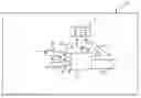
FIG. 1 shows a schematic representation of a drive unit for a vehicle, and
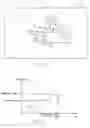
FIG. 2 shows a diagram of a simulation of a moving vehicle.
The drive unit shown in FIG. 1 in a motor vehicle A comprises an internal combustion engine 1, which is driven by an automated transmission 2. The engine 1 and the transmission 2 are controlled by an electronic control unit 3 comprising an engine control portion 4 and a transmission control portion 5 which communicate with each other. The control can be effected in accordance with the model which is described in the above mentioned WO 03/041988 and which is symbolized by the arrows “a” and “b” for engine control, and “c” and “d” for transmission control.
6 designates an intake conduit to the engine combustion chambers and 7 indicates an exhaust conduit from the engine combustion chambers. The conduits 6 and 7 communicate with each other via conduit 8 through which exhaust in the conduit 7 can be recirculated to the intake conduit 6. In the conduit 8, there is a valve 9 (the EGR valve) by means of which the volume of recirculated exhaust can be controlled continuously between zero (closed valve) and a predetermined maximum value per unit of time. The valve 9 is controlled, as symbolized by the arrow “e” in a known manner by the control unit 3 continuously during the operation of the engine in relation to engine operating conditions, so that the best fuel consumption is always obtained at the same time as the requirements of low particle and NOx emissions are fulfilled.
The forward motion of the vehicle is recorded in the control unit 3 in the form of increasing engine rpm as a function of time, which is marked in FIG. 2 with a solid curve “f”. With information on accelerator pedal position and information from the GPS equipment, for example, with electronic topographical maps, there can be simulated the future driving resistance and the time from a current rpm to an rpm at which the next gearshifting in the transmission is estimated to take place. This is marked with a dotted extension “g” of the curve “f”. For a detailed description of how the vehicle driving can be simulated on the basis of a model, reference is made to the above mentioned WO 03/041988.
Within the time period marked in FIG. 2 from the current engine rpm to the rpm for the next gearshift, the control unit 3 regulates the EGR valve 8 towards its closed position, so that the engine intake conduits 6 are emptied of recirculated exhaust volumes when the control unit 3 reduces the engine torque and initiates gearshift. In this manner, an override function is obtained which takes over the momentary intrareferential engine control of the recirculation of exhaust to the intake side of the engine.
Other future transients in the engine operating state than shifting of gears and which can be computed in the above described manner are, for example, torque reduction when the vehicle approaches the crest of a hill, and torque increase after the end of a downhill incline.
Claims
1. Method of regulating, in an internal combustion engine (1) in a moving vehicle (A), the recirculation of exhaust from the exhaust side (7) of the engine to the intake side (6) of the engine, characterized in that the future driving resistance of the vehicle (A) is calculated, that the time until a future transient in the engine operating state is calculated, and that the exhaust return flow is regulated during this time to optimize fuel consumption and emissions, when the transient takes place.
2. Method according to claim 1 for regulating return exhaust flow in connection with gearshifting in an automated transmission (2) coupled to the engine (1), characterized in that the time until a future shifting between gears is calculated, and that the exhaust return flow during this time is restricted to optimize fuel consumption and emissions during the shifting between gears.
3. Vehicle with an internal combustion engine (1) with electronic control means (3) which control the supply of fuel to the engine combustion chambers and recirculation of exhaust from the exhaust side (7) of the engine to the engine intake side (6), characterized in that the control means (3) are disposed, while the vehicle is moving, on the basis of input information on at least road incline and throttle position, to calculate future driving resistance and the time until a future transient in the engine operating state, and to control the exhaust return flow by regulating valve means (9) during this time to optimize fuel consumption and emissions when the transient takes place.
4. Vehicle according to claim 3 with an automated transmission (2) coupled to the engine (1), characterized in that the control means (3) have engine and transmission control functions and are disposed to calculate the time until a future shifting of gears and control the exhaust return flow by regulating valve means (9) during this time to optmize fuel consumption and emissions during the gearshifting.
Images & Drawings included:
Sources:
- United States Patent and Trademark Office - verify current appl. status at the USPTO↗
Recent applications in this class:
- » 20250249883 2025-08-07
HYBRID SYSTEM EMISSIONS MANAGEMENT - » 20250236279 2025-07-24
DOWN-SHIFT ACCELERATION OVERSHOOT COMPENSATION IN AUTOMOTIVE ELECTRONIC LONGITUDINAL DYNAMICS CONTROL OF AUTONOMOUS MOTOR VEHICLES - » 20250187579 2025-06-12
VEHICLE CONTROL DEVICE - » 20250178582 2025-06-05
AI-Based Traction Control System Using Real-Time RPM Analysis - » 20250162567 2025-05-22
VEHICLE - » 20250162566 2025-05-22
Work Machine Parameter Selection Device and Parameter Recommendation System - » 20240416890 2024-12-19
Control device for vehicle, control method for vehicle, and non-transitory storage medium - » 20240416889 2024-12-19
Methods and apparatus for mitigating fuel in oil - » 20240409080 2024-12-12
METHODS AND APPARATUS FOR MITIGATING FUEL IN OIL - » 20240391449 2024-11-28
CONTROL ARRANGEMENT AND METHOD FOR SHUTTING DOWN A COMBUSTION ENGINE
Recent applications for this Assignee:
- » 20210160433 2021-05-27
Method consisting in using at least one vehicle camera to check whether certain elements of the vehicle are in a safe condition before starting off - » 20200290585 2020-09-17
By-pass of air supply protection for electronic parking brake system and vehicle comprising such system - » 20200224567 2020-07-16
Process consisting in cooling at least one component, such as a sensor, arranged within a compartment of an exhaust after treatment system of a vehicle - » 20200207317 2020-07-02
Utilizing a park brake system to improve the deceleration of a vehicle in the event of failure of the service brake system - » 20200139942 2020-05-07
Vehicle camera system comprising an integrated lens cleaning mechanism, vehicle comprising such camera system and method - » 20150321657 2015-11-12
Method for controlling a hybrid vehicle electrical system - » 20140322091 2014-10-30
Method and arrangement for cleaning a particle filter - » 20120265403 2012-10-18
Method and a system for assisting a driver of a vehicle during operation - » 20100211279 2010-08-19
Method and arrangement for measuring and estimating a brake factor in a vehicle brake system - » 20100095928 2010-04-22
Device for reducing soot emissions in a vehicle combustion engine