Cleaning machine with sound suppression system
US20060254020A1
2006-11-16
11/274,897
2005-11-14
Abstract:
A cleaning machine with a sound suppression system may include a waste recovery tank and a centrifugal-bypass vacuum motor assembly. The vacuum motor assembly may include a working-air flow path and a separate motor-ventilating-air flow path, with the working-air flow path including a working-air inlet and a working-air outlet. The working-air inlet may be fluidly connectable to the waste recovery tank, whereby the vacuum motor assembly may enable a soil-containing fluid to be vacuumed into the waste recovery tank. The cleaning machine also may include a sound-suppression hood that covers at least a part of the vacuum motor assembly. Alternatively, or in addition to the sound-suppression hood, the cleaning machine may include a first muffler assembly and a second muffler assembly. The first muffler assembly may be fluidly connected to the working-air outlet; and the second muffler assembly may be fluidly connected to the first muffler assembly. In this fashion, sound produced by the vacuum motor assembly may be suppressed.
Inventors:
- Robert S. Robinson 9 🇺🇸 Hamilton, OH, United States
- David W. Lloyd 5 🇺🇸 Hamilton, OH, United States
- Gary G. Robinson 1 🇺🇸 Hamilton, OH, United States
Interested in similar patents?
Get notified when new applications in this technology area are published.
Classification:
A47L11/4097 » CPC main
Machines for cleaning floors, carpets, furniture, walls, or wall coverings; Parts or details of machines not groups - , , e.g. handles, arrangements of switches, skirts, buffers, levers Means for exhaust-air diffusion; Exhaust-air treatment, e.g. air purification; Means for sound or vibration damping
A47L7/0028 » CPC further
Suction cleaners adapted for additional purposes ; Tables with suction openings for cleaning purposes; Containers for cleaning articles by suction; Suction cleaners adapted to cleaning of brushes; Suction cleaners adapted to taking-up liquids; Suction cleaners adapted to take up liquids, e.g. wet or dry vacuum cleaners; Recovery tanks Security means, e.g. float valves or level switches for preventing overflow
A47L7/0042 » CPC further
Suction cleaners adapted for additional purposes ; Tables with suction openings for cleaning purposes; Containers for cleaning articles by suction; Suction cleaners adapted to cleaning of brushes; Suction cleaners adapted to taking-up liquids; Suction cleaners adapted to take up liquids, e.g. wet or dry vacuum cleaners Gaskets; Sealing means
A47L9/0081 » CPC further
Details or accessories of suction cleaners, e.g. mechanical means for controlling the suction or for effecting pulsating action; Storing devices specially adapted to suction cleaners or parts thereof; Carrying-vehicles specially adapted for suction cleaners Means for exhaust-air diffusion; Means for sound or vibration damping
A47L5/00 IPC
Suction cleaners
A47L5/00 IPC
Structural features of suction cleaners
A47L9/00 IPC
Details or accessories of suction cleaners, e.g. mechanical means for controlling the suction or for effecting pulsating action; Storing devices specially adapted to suction cleaners or parts thereof; Carrying-vehicles specially adapted for suction cleaners
Description
CROSS-REFERENCE TO RELATED APPLICATIONThis patent document claims the benefit of the filing date of Provisional Application for Patent No. 60/627,728 entitled “Muffler System for Vacuum Motor and Method of Using Same” and filed on Nov. 12, 2004. The entire disclosure of Provisional Application for Patent No. 60/627,728 is incorporated into this patent document by reference.
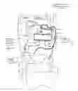
BRIEF DESCRIPTION OF THE DRAWINGSFIG. 1 is a side elevation view, partially broken away, of an embodiment of the invention;
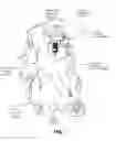
FIG. 2 is a rear perspective view, partially broken away, of a portion of an embodiment of the invention, the embodiment being substantially similar to the embodiment of FIG. 1;
FIG. 3 is a side elevation view, partially broken away, of a portion of the embodiment of FIG. 1;
FIG. 4 is an elevation view, partially broken away, of a portion of the embodiment of FIG. 1, including a first muffler assembly; and
FIG. 5 is an elevation view, partially broken away, of a portion of the embodiment of FIG. 1, including a second muffler assembly.
DETAILED DESCRIPTION OF EMBODIMENTS OF THE INVENTIONThis patent document incorporates the following patent documents in their entirety by reference: co-pending U.S. patent application Ser. No. 10/685,259 entitled “Ergonomic Multi-Functional Cleaning Machine” and filed on Oct. 14, 2003; U.S. Pat. No. 6,206,980 entitled “Multi-Functional Cleaning Machine” and issued on Mar. 27, 2001; and co-pending U.S. patent application Ser. No. 10/622,520 entitled “Ergonomic Multi-Functional Cleaning Machine” and filed on Jul. 18, 2003.
Claims
What is claimed is:1. A cleaning machine, comprising:
a waste recovery tank;
a centrifugal-bypass vacuum motor assembly including a working-air flow path and a separate motor-ventilating-air flow path, with the working-air flow path including a working-air inlet and a working-air outlet, the working-air inlet fluidly connectable to the waste recovery tank, the vacuum motor assembly enabling a soil-containing fluid to be vacuumed into the waste recovery tank;
a sound-suppression hood that covers at least a part of the vacuum motor assembly;
a first muffler assembly fluidly connected to the working-air outlet; and
a second muffler assembly fluidly connected to the first muffler assembly,
whereby sound produced by the vacuum motor assembly may be suppressed.
2. The cleaning machine of claim 1 wherein the vacuum motor assembly includes a motor-subassembly housing, and the sound-suppression hood covers at least a part of the motor-subassembly housing.
3. The cleaning machine of claim 2 wherein the sound-suppression hood includes a top wall and a circumferential sidewall depending from the top wall.
4. The cleaning machine of claim 3 wherein the vacuum motor assembly includes a working-air-subassembly housing, and the sound-suppression hood includes a bottom wall depending from the circumferential sidewall, the bottom wall being positioned adjacent the working-air-subassembly housing.
5. The cleaning machine of claim 4 further including a gasket positioned between the bottom wall and the working-air-subassembly housing.
6. The cleaning machine of claim 1 wherein the sound-suppression hood includes a ventilating-air inlet and a ventilating-air outlet.
7. The cleaning machine of claim 6 further including padding at the ventilating-air inlet, the padding operable to further suppress sound produced by the vacuum motor assembly, and to filter air entering the ventilating-air inlet.
8. The cleaning machine of claim 6 further including an electromechanical compartment cover mountable on the waste recovery tank, the electromechanical compartment cover operable to cover the vacuum motor assembly and the sound-suppression hood, the cleaning machine further including a ventilating-air exhaust conduit comprising a first end fluidly connected to the ventilating-air outlet, and a second end extending toward an opening in the electromechanical compartment cover.
9. The cleaning machine of claim 1 wherein the waste recovery tank includes a rim defining a suction outlet, and the vacuum motor assembly includes a working-air-subassembly housing comprising a bottom wall that includes at least a part of the working-air inlet, the bottom wall being positioned adjacent an exterior surface of the waste recovery tank, whereby the suction outlet is in fluid communication with the working-air inlet.
10. The cleaning machine of claim 9 further including a gasket positioned between the bottom wall and the exterior surface of the waste recovery tank.
11. The cleaning machine of claim 1 further including a float shut-off assembly positioned in the waste recovery tank, the shut-off assembly including a cylindrical filter and padding at the cylindrical filter.
12. The cleaning machine of claim 1 further including a fresh liquid tank.
13. The cleaning machine of claim 12 further including a fresh liquid pump, the fresh liquid pump enabling a liquid or solution to be pumped from the fresh liquid tank.
14. The cleaning machine of claim 1 further including a blower motor assembly.
15. A cleaning machine, comprising:
a waste recovery tank;
a centrifugal-bypass vacuum motor assembly including a working-air flow path and a separate motor-ventilating-air flow path, with the working-air flow path including a working-air inlet and a working-air outlet, the working-air inlet fluidly connectable to the waste recovery tank, the vacuum motor assembly enabling a soil-containing fluid to be vacuumed into the waste recovery tank; and
a sound-suppression hood that covers at least a part of the vacuum motor assembly,
whereby sound produced by the vacuum motor assembly may be suppressed.
16. The cleaning machine of claim 15 wherein the vacuum motor assembly includes a motor-subassembly housing, and the sound-suppression hood covers at least a part of the motor-subassembly housing.
17. The cleaning machine of claim 16 wherein the sound-suppression hood includes a top wall and a circumferential sidewall depending from the top wall.
18. The cleaning machine of claim 17 wherein the vacuum motor assembly includes a working-air-subassembly housing, and the sound-suppression hood includes a bottom wall depending from the circumferential sidewall, the bottom wall being positioned adjacent the working-air-subassembly housing.
19. The cleaning machine of claim 18 further including a gasket positioned between the bottom wall and the working-air-subassembly housing.
20. The cleaning machine of claim 15 wherein the sound-suppression hood includes a ventilating-air inlet and a ventilating-air outlet.
21. The cleaning machine of claim 20 further including padding at the ventilating-air inlet, the padding operable to further suppress sound produced by the vacuum motor assembly, and to filter air entering the ventilating-air inlet.
22. The cleaning machine of claim 20 further including an electromechanical compartment cover mountable on the waste recovery tank, the electromechanical compartment cover operable to cover the vacuum motor assembly and the sound-suppression hood, the cleaning machine further including a ventilating-air exhaust conduit comprising a first end fluidly connected to the ventilating-air outlet, and a second end extending toward an opening in the electromechanical compartment cover.
23. The cleaning machine of claim 15 wherein the waste recovery tank includes a rim defining a suction outlet, and the vacuum motor assembly includes a working-air-subassembly housing comprising a bottom wall that includes at least a part of the working-air inlet, the bottom wall being positioned adjacent an exterior surface of the waste recovery tank, whereby the suction outlet is in fluid communication with the working-air inlet.
24. The cleaning machine of claim 23 further including a gasket positioned between the bottom wall and the exterior surface of the waste recovery tank.
25. A cleaning machine, comprising:
a waste recovery tank;
a centrifugal-bypass vacuum motor assembly including a working-air flow path and a separate motor-ventilating-air flow path, with the working-air flow path including a working-air inlet and a working-air outlet, the working-air inlet fluidly connectable to the waste recovery tank, the vacuum motor assembly enabling a soil-containing fluid to be vacuumed into the waste recovery tank;
a first muffler assembly fluidly connected to the working-air outlet; and
a second muffler assembly fluidly connected to the first muffler assembly,
whereby sound produced by the vacuum motor assembly may be suppressed.
26. The cleaning machine of claim 25 wherein the first muffler assembly comprises an elongated cylindrical tube including a circumferential side wall, a first end wall, and a second end wall defining a chamber, the tube further including a constant cross-sectional inside diameter along its length between the first and second end walls, an air inlet in the sidewall near the first end, and an air outlet in the sidewall near the second.
27. The cleaning machine of claim 26 further including a first conduit between the working-air outlet and the air inlet of the first muffler, and a second conduit between the air outlet of the first muffler and the second muffler, the first conduit including a 90° elbow at the air inlet, and the second conduit including a 90° elbow at the air outlet, whereby air flow is redirected sharply, immediately prior to entering and immediately upon exiting, the first-muffler chamber, thereby enabling sound produced by the vacuum motor assembly to be further supressed.
28. The cleaning machine of claim 26 wherein the first muffler assembly is in a substantially horizontal orientation when the cleaning machine is positioned on a level support surface.
29. The cleaning machine of claim 26 further including padding within the chamber of the first muffler assembly.
Images & Drawings included:


Sources:
- United States Patent and Trademark Office - verify current appl. status at the USPTO↗
Recent applications in this class:
- » 20240164612 2024-05-23
FLOOR CLEANING APPARATUS - » 20190090712 2019-03-28
Moving robot and control method thereof using artificial intelligence - » 20190075992 2019-03-14
SCRUBBER HEAD FOR FLOOR CLEANER - » 20180353044 2018-12-13
Automatically moving floor treatment appliance - » 20170055797 2017-03-02
Robot cleaner - » 20170020356 2017-01-26
Mute operation method and apparatus for automatic cleaning device - » 20160051111 2016-02-25
CLEANING DEVICE CAPABLE OF REMOVING MOISTURE UTILIZING EXHAUST HEAT - » 20140159257 2014-06-12
Wet dust suppression floor cleaning system - » 20140026338 2014-01-30
AUTONOMOUS CLEANING DEVICE - » 20050166358 2005-08-04
Cleaner