Process and installation for supplying gaseous carbon monoxide and/or a gaseous mixture containing at least 10% carbon monoxide
US20060254311A1
2006-11-16
10/557,013
2004-05-06
Abstract:
In a process for providing gaseous carbon monoxide and/or a mixture containing at least 10% carbon monoxide, carbon monoxide is stored in liquid form in a storage vessel (47) and, when required, is withdrawn from the storage vessel and vaporised in a vaporiser (53) to produce gaseous carbon monoxide when the gaseous production of carbon monoxide is insufficient.
Inventors:
- Jean BILLY 5 🇫🇷 Le Plessis-Trevise, France
- Natacha Haik-Beraud 5 🇫🇷 Nogent-Sur-Marne, France
Interested in similar patents?
Get notified when new applications in this technology area are published.
Classification:
C01B3/506 » CPC main
Hydrogen; Gaseous mixtures containing hydrogen; Separation of hydrogen from mixtures containing it ; Purification of hydrogen; Separation of hydrogen or hydrogen containing gases from gaseous mixtures, e.g. purification at low temperatures
C01B32/40 » CPC further
Carbon; Compounds thereof Carbon monoxide
F25J3/0223 » CPC further
Processes or apparatus for separating the constituents of gaseous or liquefied gaseous mixtures involving the use of liquefaction or solidification by rectification, i.e. by continuous interchange of heat and material between a vapour stream and a liquid stream characterised by the feed stream H/CO mixtures, i.e. synthesis gas; Water gas or shifted synthesis gas
F25J3/0252 » CPC further
Processes or apparatus for separating the constituents of gaseous or liquefied gaseous mixtures involving the use of liquefaction or solidification by rectification, i.e. by continuous interchange of heat and material between a vapour stream and a liquid stream characterised by the separated product stream separation of hydrogen
F25J3/0261 » CPC further
Processes or apparatus for separating the constituents of gaseous or liquefied gaseous mixtures involving the use of liquefaction or solidification by rectification, i.e. by continuous interchange of heat and material between a vapour stream and a liquid stream characterised by the separated product stream separation of carbon monoxide
F25J3/0271 » CPC further
Processes or apparatus for separating the constituents of gaseous or liquefied gaseous mixtures involving the use of liquefaction or solidification by rectification, i.e. by continuous interchange of heat and material between a vapour stream and a liquid stream characterised by the separated product stream separation of H/CO mixtures, i.e. of synthesis gas
C01B2203/046 » CPC further
Integrated processes for the production of hydrogen or synthesis gas containing a purification step for the hydrogen or the synthesis gas Purification by cryogenic separation
C01B2203/047 » CPC further
Integrated processes for the production of hydrogen or synthesis gas containing a purification step for the hydrogen or the synthesis gas; Composition of the impurity the impurity being carbon monoxide
C01B2203/048 » CPC further
Integrated processes for the production of hydrogen or synthesis gas containing a purification step for the hydrogen or the synthesis gas; Composition of the impurity the impurity being an organic compound
F25J2200/70 » CPC further
Processes or apparatus using separation by rectification Refluxing the column with a condensed part of the feed stream, i.e. fractionator top is stripped or self-rectified
F25J2200/76 » CPC further
Processes or apparatus using separation by rectification Refluxing the column with condensed overhead gas being cycled in a quasi-closed loop refrigeration cycle
F25J2200/94 » CPC further
Processes or apparatus using separation by rectification; Details relating to column internals, e.g. structured packing, gas or liquid distribution Details relating to the withdrawal point
F25J2205/30 » CPC further
Processes or apparatus using other separation and/or other processing means using a washing, e.g. "scrubbing" or bubble column for purification purposes
F25J2210/42 » CPC further
Processes characterised by the type or other details of the feed stream Nitrogen
F25J2215/02 » CPC further
Processes characterised by the type or other details of the product stream Mixing or blending of fluids to yield a certain product
F25J2215/04 » CPC further
Processes characterised by the type or other details of the product stream Recovery of liquid products
F25J2235/02 » CPC further
Processes or apparatus involving steps for increasing the pressure or for conveying of liquid process streams using a pump in general or hydrostatic pressure increase
F25J2245/02 » CPC further
Processes or apparatus involving steps for recycling of process streams Recycle of a stream in general, e.g. a by-pass stream
F25J2250/30 » CPC further
Details related to the use of reboiler-condensers External or auxiliary boiler-condenser in general, e.g. without a specified fluid or one fluid is not a primary air component or an intermediate fluid
F25J2270/02 » CPC further
Refrigeration techniques used Internal refrigeration with liquid vaporising loop
F25J2270/04 » CPC further
Refrigeration techniques used Internal refrigeration with work-producing gas expansion loop
F25J2270/08 » CPC further
Refrigeration techniques used Internal refrigeration by flash gas recovery loop
F25J2270/24 » CPC further
Refrigeration techniques used Quasi-closed internal or closed external carbon monoxide refrigeration cycle
F25J2270/904 » CPC further
Refrigeration techniques used; External refrigeration, e.g. conventional closed-loop mechanical refrigeration unit using Freon or NH, unspecified external refrigeration by liquid or gaseous cryogen in an open loop
F25J2280/02 » CPC further
Control of the process or apparatus Control in general, load changes, different modes ("runs"), measurements
F25J2290/62 » CPC further
Other details not covered by groups - Details of storing a fluid in a tank
F25J3/00 IPC
Processes or apparatus for separating the constituents of gaseous or liquefied gaseous mixtures involving the use of liquefaction or solidification
Description
This invention concerns processes and installations for providing gaseous carbon monoxide and/or a mixture containing at least 10% carbon monoxide. In particular it concerns the supply of carbon monoxide by vaporisation of liquid carbon monoxide when an industrial installation, such as a separation unit, cannot provide all or part of the gaseous carbon monoxide product.
At the beginning of the cycle of the purification unit used to purify the feed gas sent to the carbon monoxide separation unit, when one of the adsorbent beds passes from the regeneration step to the adsorption step, the carbon monoxide is absorbed in great quantities by the adsorbents, leading to a reduction in the amount of carbon monoxide produced by the separation unit. This effect is described for example in EP-A-0 748 765. The beds may contain adsorbents such as alumina or zeolites, such as molecular sieves.
To reduce this effect, as disclosed in French patent application FR01/06041, the purification cycle can be adapted so that following the regeneration step, only a limited amount of feed gas is sent to the bed at the beginning of the adsorption step (around 5% of the normal feed flow).
Frequently even these measures are not sufficient to ensure that the amount of carbon monoxide produced does not deviate from the required amount by more than a certain percentage. Another solution in this case can be to use a larger reactor to produce the feed gas, which of course entails extra costs.
All percentages mentioned are molar percentages and all pressures are absolute pressures.
EP-A-0837031 and EP-A-1245533 show a liquid carbon monoxide storage vessel incorporated at the top of a carbon monoxide-methane separation column, the liquid carbon monoxide being used to provide reflux for the column and to provide cooling for the methane wash column and, in the case of EP-A-0837031 for the main heat exchanger wherein the synthesis gas is used to its distillation temperature. In U.S. Pat. No. 3,886,756 and U.S. Pat. No. 4,102,659, independent vessels collect liquid carbon monoxide used in the carbon monoxide cycle used in the methane wash process.
According to the present invention, there is provided a process for supplying gaseous carbon monoxide and/or a gaseous mixture containing at least 10% carbon monoxide in which:
-
- a) a feed gas containing carbon monoxide as at least one of its principal components and preferably at least one of nitrogen, methane and hydrogen as other principal components separated in a separation unit
- b) the separation unit separates the feed gas to produce gaseous carbon monoxide, wherein the gaseous carbon monoxide is a final product and/or the gaseous mixture containing at least 10% carbon monoxide is a final product, formed by mixing gaseous carbon monoxide with at least one other gas from the separation unit
- c) liquid carbon monoxide is stored in a storage vessel
- d) liquid carbon monoxide is withdrawn from the storage vessel and at least part of the liquid is vaporised to produce gaseous carbon monoxide, the gaseous carbon monoxide forming at least part of the gaseous carbon monoxide product and/or at least part of the gaseous mixture containing at least 10% carbon monoxide
characterised in that the withdrawal and vaporisation of the liquid carbon monoxide take place - i) if there is a reduction in the amount of feed gas sent to the separation unit and/or
- ii) where the feed gas is purified using an adsorption step in one of at least two adsorbent beds to produce a purified feed gas to be sent to the separation unit, during at least part of the period at the beginning of the adsorption step before the adsorbent bed is saturated with carbon monoxide and/or
- iii) when the product requirement exceeds the maximum capacity of the separation unit.
According to optional features of the invention:
-
- the gaseous carbon monoxide separated in the unit is removed in gaseous form from a column or a column top condenser of the unit or a permeator of the unit or a purification bed of the unit
- the separation unit operates by cryogenic distillation, permeation or adsorption;
- the separation unit operates by cryogenic distillation and comprising the steps of purifying the feed gas using an adsorption step in one of at least two adsorbent beds to produce a purified feed gas to be sent to the separation unit, cooling at least part of the purified feed gas in a heat exchanger to form cooled purified feed gas, feeding the separation unit with at least part of the cooled purified feed gas and separating the purified feed gas by cryogenic distillation in a system of columns to produce gaseous carbon monoxide and/or being mixed with another gas to form a gaseous mixture containing at least 10% carbon monoxide as final product(s);
- the cryogenic separation unit comprises a CO/CH4 column for separating a mixture containing principally carbon monoxide and methane, the storage vessel preferably forming an integral part of this column;
- at least part of the gaseous carbon monoxide product is withdrawn from the CO/CH4 column and the liquid carbon monoxide to be sent to the storage vessel is either formed by liquefying carbon monoxide from a carbon monoxide refrigeration cycle forming part of the separation unit and/or by removing liquid carbon monoxide from the CO/CH4 column and/or by liquefying gaseous carbon monoxide in a heat exchanger by heat exchange between the gaseous carbon monoxide and a colder fluid derived from an external source, for example liquid nitrogen;
- the separation unit comprises a methane wash column and wherein a first flow of liquid carbon monoxide is vaporised to cool the methane wash column, a second flow of liquid carbon monoxide is vaporised in the heat exchanger and a third flow of liquid carbon monoxide is vaporised only if one of conditions i) to iii) of Claim 1 is fulfilled;
- the withdrawn liquid is pressurised prior to vaporisation using at least one pump or the vaporised liquid is compressed in a compressor;
- the storage vessel stores the liquid carbon monoxide at a pressure between 1 and 60 bars, preferably at the supply pressure of the gaseous carbon monoxide and/or a gaseous mixture containing at least 10% carbon monoxide;
- the vaporised liquid carbon monoxide from the vaporiser is compressed using a compressor of a carbon monoxide refrigeration cycle and/or a carbon monoxide product compressor.
According to another aspect of the invention, there is provided an installation for supplying gaseous carbon monoxide and/or a gaseous mixture containing at least 10% carbon monoxide by vaporisation of liquid carbon monoxide including
-
- a) a separation unit
- b) a storage vessel
- c) a vaporiser
- d) a conduit to send liquid carbon monoxide to the storage vessel
- e) a conduit for withdrawing liquid carbon monoxide from the storage vessel and for sending liquid carbon monoxide to the vaporiser where it is vaporised
- f) a conduit for removing vaporised carbon monoxide from the vaporiser
- g) a conduit for sending a feed gas containing carbon monoxide as a principal component and preferably at least one of nitrogen, methane and hydrogen as other principal components to the separation unit and a conduit for removing gaseous carbon monoxide from the separation unit and characterised in that it comprises
- h) means for sending the liquid carbon monoxide to the vaporiser
- i) if there is a reduction in the amount of feed gas sent to the separation unit and/or
- ii) where there is an adsorption unit upstream the separation unit, during at least part of the period at the beginning of the adsorption step before the adsorbent bed is saturated with carbon monoxide and/or
- iii) when the product requirement exceeds the maximum capacity of the separation unit.
This installation is adapted to operate according to the process of Claim 1. According to optional features of the invention:
-
- the separation unit is a cryogenic distillation unit, an adsorption unit or a permeation unit;
- the separation unit includes a cold box, a system of columns comprising at least one cryogenic distillation column, means for sending cooled purified feed gas containing carbon monoxide as one principal component and at least one of nitrogen, methane and hydrogen as other principal components to the system of columns and further comprising a heat exchanger and an adsorption unit;
- the cryogenic separation columns include a methane washing column associated with a heat exchanger used to cool the column by heat exchange with vaporising carbon monoxide and the vaporiser is a heat exchanger other than that associated with the methane washing column;
- the cryogenic separation columns comprise a methane washing column, a methane/carbon monoxide separation column and a stripping column or a phase separator, and the cold box contains a conduit for feeding bottom liquid from the methane washing column to the stripping column or to the phase separator, a conduit for feeding bottom liquid from the stripping column or from the phase separator to the methane/carbon monoxide separation column, a conduit for removing carbon monoxide from the methane/carbon monoxide separation column, a conduit for removing methane from the methane/carbon monoxide separation column and a conduit for sending methane from the methane/carbon monoxide separation column to the top of the methane washing column;
- the storage vessel is within the cold box and is fed with liquid carbon monoxide derived from one of the cryogenic separation columns, preferably from a carbon monoxide/methane separation column;
- the vaporiser is situated outside the cold box of the cryogenic separation unit and preferably permits heat exchange with the atmosphere or a fluid warmed than the carbon monoxide to be vaporised.
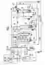
The invention will now be described in greater detail with respect to the figure which is highly simplified but contains the main elements of one installation according to the invention.
FIG. 1 shows an apparatus for separating a mixture containing principally methane, carbon monoxide and hydrogen. The mixture may also contain small amounts of nitrogen, carbon dioxide, humidity, higher hydrocarbons etc. This mixture is generally synthesis gas produced by a partial oxidation unit, a steam methane reformer or an autothermal reformer.
The mixture 1 is purified in a front end purification unit 3 at around ambient temperature to removed water and carbon dioxide. Then the mixture is cooled to a cryogenic temperature in a heat exchanger 5 and sent to the bottom of a methane wash column 7 operating at a pressure between 10 and 60 bars. A methane wash stream 9 is fed to the top of column 7 and a hydrogen enriched stream 11 is removed from the top of the column. From the bottom of the column is removed a liquid stream 13 enriched in carbon monoxide.
Stream 13 is further treated before being sent to the stripping column 19 which operates at between 4 and 17 bars, at least one feed stream formed from stream 13 being sent to the top of stripping column 19. Alternatively if a methane stream is fed to the top of stripping column 19, the feed stream is feed thereto at a lower point. The gas 21 from the top of the stripping column is warmed in the exchanger 5 and is used as fuel or burnt. The liquid stream 23 from the bottom of the stripping column 19 is further treated before being sent to the column 27. In particular, several feeds (liquid, dual phase, gaseous) at different levels may be provided to the column 27. Column 27 operates at between 1 and 10 bars, often around 2.5 bars. There it is separated to form a methane rich liquid 29 at the bottom of the column and a carbon monoxide rich gas 31 at the top of the column. Part of the methane rich liquid is pumped and sent to the top of the methane washing column and the rest is removed as a purge stream. The two portions of the methane rich liquid may be removed separately from the column. In this example, the methane rich liquid is pumped by pump 33 and sent in part to the top of the methane washing column 7 and the remaining purge stream is mixed with stream 21. The part to be mixed with stream 21 need not be pumped.
The carbon monoxide rich product stream 31 is compressed in a compressor 35 and is removed as a compressed product gas 37.
Refrigeration for the system is provided by a carbon monoxide cycle of which the compressor 35 forms part. The carbon monoxide is compressed in compressor 35 to a pressure of between 10 and 60 bars. Part of the compressed carbon monoxide 39 is cooled in exchanger 5 to an intermediate temperature of the exchanger and then expanded in turbine 41. The expanded carbon monoxide gas is warmed in the exchanger 5 and recycled to the compressor 35 at the entry thereof or an intermediate pressure thereof. The unexpanded carbon monoxide 43 serves to reboil columns 19 and 27 and the thereby cooled carbon monoxide is expanded in valve 45 and sent to storage vessel 47.
In this particular case, the storage vessel 47 forms an integral part of the column 27 and additionally serves to provide reflux to the top of column 27, to supply liquid carbon monoxide to cool the methane wash column 7 and to supply liquid carbon monoxide directly to the main heat exchanger 5 where it is vaporised to balance the heat exchange diagram at the cold end of the heat exchanger 5. However there could be two storage vessels, one of which supplies the reflux to the top of the column 27 and the other of which is independent of this column or any column. This independent storage vessel could be placed within or outside the cold box (not shown) which encloses the columns 7,19,27, the exchanger 5 and the turbine 41, optionally turbine 89 which expands part 87 of gas 71.
The storage vessel may be pressurised so that the carbon monoxide is stored at between above 1 and below 60 bars. Ideally the storage vessel should be at a pressure which is substantially the product pressure of the carbon monoxide gas 37 or the carbon monoxide mixture 73, allowing for pressure drop in the conduits and vaporiser 53. Alternatively the carbon monoxide may be stored at atmospheric pressure and then, if required, pumped in liquid form and/or compressed in gaseous form to its final pressure.
Flash gas 49 produced by the expansion is mixed with the carbon monoxide rich gas 31 prior to compression.
A stream of liquid carbon monoxide 57 is vaporised in exchanger 59 against the gas streams within the methane wash column 7 and forms part of the gaseous carbon monoxide cycle.
A further stream of liquid carbon monoxide 61 withdrawn from the vessel 47 is vaporised in exchanger 5.
Both these liquid streams are withdrawn as part of the normal functioning of the process.
In addition, liquid 51 from the storage vessel 47 is withdrawn when required and vaporised in the vaporiser 53. The vaporiser may either allow heat exchange with ambient air, water or steam if it is outside the cold box or may be within the cold box and may be constituted by the exchanger 5 or another heat exchanger.
The vaporised carbon monoxide produced 55 is sent to the compressor 35 to form all or part of the product gas.
If the liquid to be vaporised 51 is available at high pressure, for example following a pumping process upstream of the vaporiser 53 or where the liquid is stored at high pressure, the gas produced can be directly mixed with the product gas 37. The withdrawal and vaporisation of the carbon monoxide may take place
-
- i) if there is a reduction in the amount of feed gas 1 sent to the separation unit and/or
- ii) during at least part of the period at the beginning of the adsorption step before the adsorbent bed is saturated with carbon monoxide and/or
- iii) when the product requirement exceeds the maximum capacity of the separation unit.
It will be appreciated that when none of these conditions is present the level in the storage vessel will remain constant or will rise. The level will fall whenever one of the conditions is fulfilled and the vessel will need to be replenished, for example when the amount of feed gas increases and/or when the adsorbers are saturated with carbon monoxide and/or when the product requirement is less than the maximum capacity of the separation unit. To do this, either the carbon monoxide turbine needs to be overdimensioned to replenish the vessel or else a cryogenic liquid from an outside source can be added. This cryogenic liquid may be liquid carbon monoxide from an outside source or liquid nitrogen which is then used to liquefy gaseous carbon monoxide by heat exchange in a heat exchanger.
At the beginning of the adsorption step the adsorbers are operated as described in FR01/06041 (incorporated by reference) such that the amount of feed sent to the adsorbers does not reach its full amount until the adsorber bed to which it is sent is saturated with carbon monoxide. In the example of FR01/06041, the flow starts at 5% mol. of the normal flow, then is increased to 50% mol. and finally is increased to 100%. The liquid carbon monoxide may begin to be sent to the vaporiser for example when the flow is at its smallest or alternatively may begin a few minutes before the flow is at its smallest. Preferably the liquid carbon monoxide is no longer sent to the vaporiser once the flow has increased to 50%.
In addition, it is possible to operate the separation unit so as to fill the storage vessel during the night and then use the stored carbon monoxide to provide peak requirements during the day.
Gaseous and liquid carbon monoxide are defined to be respectively a gas and a liquid containing at least 85% carbon monoxide, preferably at least 95% carbon monoxide.
The process may also be used to produce a mixture containing at least 10% carbon monoxide 73, for example an oxogas used in the production of oxoalcohols. This mixture is produced by withdrawing a gaseous mixture 71 from one of the columns of the system, warming it in exchanger 5 and enriching it by adding gaseous carbon monoxide 72 to achieve a desired concentration of carbon monoxide. Where the gaseous carbon monoxide is insufficient, part of the requirement may be provided by vaporising part of the carbon monoxide liquid from storage 47.
It will be appreciated that the invention applies to other cryogenic separation processes for mixtures containing carbon monoxide and at least one of hydrogen, nitrogen and methane as principal components, for example processes to separate mixtures of hydrogen, carbon monoxide and methane such as the partial condensation process or processes for separating mixtures containing carbon monoxide and nitrogen only as principal components.
The separation unit shown here as a cryogenic distillation unit could of course operated by permeation in a membrane system or by adsorption. In this case the liquid carbon monoxide could be imported from an external source or could be produced by liquefying part of the gaseous carbon monoxide product at times of low demand.
Claims
1-16. (canceled)
17. A process for supplying gaseous carbon monoxide and/or a gaseous mixture containing at least 10% carbon monoxide in which:
a) a feed gas (1) containing carbon monoxide as at least one of its principal components and preferably at least one of nitrogen, methane and hydrogen as other principal components is separated in a separation unit;
b) the separation unit separates the feed gas to produce gaseous carbon monoxide, wherein the gaseous carbon monoxide is a final product (37) and/or a gaseous mixture (73) is a final product containing at least 10% carbon monoxide, possibly by mixing gaseous carbon monoxide (72) with at least one other gas (71) from the separation unit;
c) liquid carbon monoxide is stored in a storage vessel (47); and
d) liquid carbon monoxide is withdrawn from the storage vessel and at least part (61) of the liquid is vaporized to produce gaseous carbon monoxide, the gaseous carbon monoxide forming at least part of the gaseous carbon monoxide product and/or being mixed with another gas to form at least part of the gaseous mixture containing at least 10% carbon monoxide,
wherein the withdrawal and vaporization of the liquid carbon monoxide take place:
i) if there is a reduction in the amount of feed gas sent to the separation unit and/or
ii) where the feed gas is purified using an adsorption step in one of at least two adsorbent beds (3) to produce a purified feed gas to be sent to the separation unit, during at least part of the period at the beginning of the adsorption step before the adsorbent bed is saturated with carbon monoxide and/or
iii) when the product requirement exceeds the maximum capacity of the separation unit.
18. The process of claim 17, wherein the separation unit operates by cryogenic distillation, permeation or adsorption.
19. The process of claim 18, wherein the separation unit operates by cryogenic distillation and comprising the steps of purifying the feed gas using an adsorption step in one of at least two adsorbent beds (3) to produce a purified feed gas to be sent to the separation unit, cooling at least part of the purified feed gas in a heat exchanger (5) to form cooled purified feed gas, feeding the separation unit with at least part of the cooled purified feed gas and separating the purified feed gas by cryogenic distillation in a system of columns (7,19,27) to produce gaseous carbon monoxide and/or a gaseous mixture containing at least 10% carbon monoxide as final product(s).
20. The process of claim 18, wherein the cryogenic separation unit comprises a CO/CH4 column (27) for separating a mixture containing principally carbon monoxide and methane, the storage vessel (47) preferably forming an integral part of this column.
21. The process of claim 20, wherein at least part of the gaseous carbon monoxide product is withdrawn from the CO/CH4 column (27) and the liquid carbon monoxide to be sent to the storage vessel is either formed by liquefying carbon monoxide from a carbon monoxide refrigeration cycle forming part of the separation unit and/or by removing liquid carbon monoxide from the CO/CH4 column and/or by liquefying gaseous carbon monoxide in a heat exchanger by heat exchange between the gaseous carbon monoxide and a colder fluid derived from an external source, for example liquid nitrogen.
23. The process of claim 17, wherein the withdrawn liquid (51) is pressurized prior to vaporization using at least one pump or the vaporized liquid is compressed in a compressor (35).
24. The process of claim 17, wherein the storage vessel (47) stores the liquid carbon monoxide at a pressure between 1 and 60 bars, preferably at the supply pressure of the gaseous carbon monoxide and/or of the gaseous mixture containing at least 10% carbon monoxide.
25. The process of claim 17, wherein the vaporized liquid carbon monoxide from the vaporizer is compressed using a compressor (35) of a carbon monoxide refrigeration cycle and/or a carbon monoxide product compressor (35).
26. An installation for supplying gaseous carbon monoxide and/or a gaseous mixture containing at least 10% carbon monoxide by vaporization of liquid carbon monoxide including:
a) a separation unit;
b) a storage vessel (47);
c) a vaporizer (53);
d) a conduit (43) to send liquid carbon monoxide to the storage vessel;
e) a conduit for withdrawing liquid carbon monoxide from the storage vessel and for sending liquid carbon monoxide to the vaporizer where it is vaporized;
f) a conduit (55) for removing vaporized carbon monoxide from the vaporizer;
g) a conduit for sending a feed gas (1) containing at least carbon monoxide as a principal component and preferably at least one of nitrogen, methane and hydrogen as other principal components to the separation unit and a conduit for removing gaseous carbon monoxide from the separation unit and characterized in that it comprises means for sending the liquid carbon monoxide to the vaporizer:
1) if there is a reduction in the amount of feed gas sent to the separation unit and/or
2) where there is an adsorption unit upstream the separation unit for purifying the feed gas, during at least part of the period at the beginning of the adsorption step before the adsorbent bed is saturated with carbon monoxide and/or
3) when the product requirement exceeds the maximum capacity of the separation unit.
27. The installation of claim 26, wherein the separation unit is a cryogenic distillation unit, an adsorption unit or a permeation unit.
28. The installation of claim 26, wherein the separation unit includes a cold box, a system of columns comprising at least one cryogenic distillation column (7, 18, 27), means for sending cooled purified feed gas (1) containing carbon monoxide as one principal component and at least one of nitrogen, methane and hydrogen as other principal components to the system of columns and further comprising a heat exchanger (5) and an adsorption unit (3).
29. The installation of claim 28, wherein the cryogenic separation columns include a methane washing column (7) associated with a heat exchanger (59) used to cool the column by heat exchange with vaporizing carbon monoxide (57) and the vaporizer (53) is a heat exchanger other than that associated with the methane washing column.
30. The installation of claim 28, wherein the cryogenic separation columns comprise a methane washing column (7), a methane/carbon monoxide separation column (27) and a stripping column (19) or a phase separator, and the cold box contains a conduit (13) for feeding bottom liquid from the methane washing column to the stripping column or to the phase separator, a conduit (23) for feeding bottom liquid from the stripping column or from the phase separator to the methane/carbon monoxide separation column, a conduit (49) for removing carbon monoxide from the methane/carbon monoxide separation column, a conduit (27) for removing methane from the methane/carbon monoxide separation column and a conduit (9) for sending methane from the methane/carbon monoxide separation column to the top of the methane washing column.
31. The installation of claim 27, wherein the storage vessel is within the cold box and is fed with liquid carbon monoxide derived from one of the cryogenic separation columns, preferably from a carbon monoxide/methane separation column (27).
32. The installation of claim 27, wherein the vaporizer (53) is situated outside the cold box of the cryogenic separation unit.
Images & Drawings included:

Sources:
- United States Patent and Trademark Office - verify current appl. status at the USPTO↗
Recent applications in this class:
- » 20250136444 2025-05-01
HYDROGEN PRODUCTION PROCESS WITH CARBON DIOXIDE CAPTURE HAVING REDUCED CARBON INTENSITY - » 20250026639 2025-01-23
EFFECTIVE USE OF CRYOGENIC SEPARATION SECTION IN SYNGAS MANUFACTURE - » 20240367970 2024-11-07
HYDROGEN PRODUCTION PROCESS WITH IMPROVED CO2 FRACTIONATION PROCESS - » 20240208813 2024-06-27
METHOD FOR SEPARATING HYDROGEN AND NITROGEN FROM CRACKED AMMONIA - » 20220356060 2022-11-10
Process and apparatus for the separation of a mixture of hydrogen and carbon monoxide at low temperature - » 20220144633 2022-05-12
Method and device for separating a gas mixture containing diborane and hydrogen - » 20210269307 2021-09-02
CARBON RECYCLING IN STEAM REFORMING PROCESS - » 20200079650 2020-03-12
Dual product Hand CO production with CO turndown - » 20170267524 2017-09-21
INCREASING HYDROGEN RECOVERY FROM CO + H2 SYNTHESIS GAS - » 20170081186 2017-03-23
Treatment method for separating carbon dioxide and hydrogen from a mixture