Canopy for an anchored boat
US20060254637A1
2006-11-16
11/116,155
2005-04-28
Abstract:
A canopy for a boat that is anchored on a dock. The canopy consists of a main support frame that is fixed with its lower ends on the dock. Both of the lower ends of the main support frame have hinge brackets attached thereto. There is a multiple of support rods hingedly attached to the hinge brackets. The support rods have a similar shape when compared to the main support frame. A weather resistant material is attached to the main support frame and is further draped over the support rods to form a canopy. There is a wind-up mechanism operated by an electric motor to collapse the canopy into a collapsed position when not in use.
Interested in similar patents?
Get notified when new applications in this technology area are published.
Classification:
E04H15/38 » CPC main
Tents or canopies, in general; Parts, components, construction details, accessories, interior equipment, specially adapted for tents, e.g. guy-line equipment, skirts, thresholds; Supporting means, e.g. frames arch-shaped type expansible, e.g. extensible in a fan type manner
E04H15/48 IPC
Tents or canopies, in general; Parts, components, construction details, accessories, interior equipment, specially adapted for tents, e.g. guy-line equipment, skirts, thresholds; Supporting means, e.g. frames collapsible, e.g. breakdown type having connecting nodes foldable, i.e. having pivoted or hinged means
Description
FIELD OF THE INVENTIONThere are many boats anchored at boat slips at docks and board walks. They are mostly kept in place without any protection from the elements, that is, direct sun light, rain or high winds. It is desirable to have the boats anchored under some protective cover.
BACKGROUND OF THE INVENTIONIn many areas there are stationary boat covers that are unsightly because they are built over the water where a boat is usually anchored or tied to a dock. The stationary or rigid structure supports a roof made out of wood or plastic material. The outboard supports have to be driven into the water so that the roof can be supported thereby. The supports driven into the water have a short life span and are expensive to erect, maintain or replace. In many location there are ordinances issued by a city, county or the state that prohibit the erection of stationary or rigid boat covers.
BRIEF DESCRIPTION OF THE INVENTIONThe inventive boat cover consists of a canopy that can be deployed over the boat while the boat is anchored or tied to a boat dock and can be opened or collapsed when the boat is not present at a location. The canopy is made of a flexible material that is supported by several movable supports that are hinged on the dock and can be deployed over the boat and will completely cover or hide the boat when on anchor. The canopy is being deployed and retracted by an electric motor which can be remote controlled. It is also desirable to have a closure of the main frame work to completely enclose the boat so that the boat can be used for enjoyment.
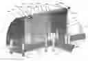
BRIEF DESCRIPTION OF THE DRAWINGSFIG. 1 is a perspective view of the boat canopy in its deployed state;
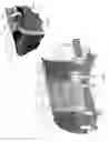
FIG. 2 is a perspective view of a drive mechanism for the canopy;
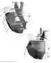
FIG. 3 is a perspective view of the boat canopy as seen from a different angle;
FIG. 4 is a perspective view of the canopy having a different shape.
DETAILED DESCRIPTION OF THE INVENTIONFIG. 1 is a perspective view of the boat canopy when it is fully deployed. The boat B is docked or anchored on a boat dock 2 which access by way of the board walk 1. The boat dock and the board walk are supported by supports or pilings 3 which are driven into the bottom of the water. The canopy can also be installed in an area where there are walls such as break walls.
The only installation necessary or required is a frame work 4 which determines the size of the canopy. The frame work can be constructed in an L-shape form to gain rigidity and to somewhat hide the canopy when it is collapsed including its support rods. The bottom of each leg is anchored to the top of the boat dock in a rigid manner.
The canopy 5 should be constructed of a supple but weather resistant material. It could be made out of canvas having a weather resistant coating thereon. The canopy 5 could be the same material that is used in covering swimming pools when not in use. In addition, the canopy could be an insect screening material.
The canopy 5 is supported by rigid rods 7 and 8 that are shaped in such a manner to determine the final shape of the canopy. In FIG. 1 the support rods 7 and 8 take the shape of the support frame work 4, that is, a rectangular shape. This shape is desirable because once the canopy is collapsed, the support rods including the canopy material will nestle within the frame work 4. The canopy 5 also has side panels 6 which will ultimately determine the shape of the canopy when seen from either side of the canopy. In FIG. 1, there are shown only two support rods 7 and 8 but more support rods could be used dictated by the size of the final canopy. When the canopy 5 is deployed, it maintains its rectangular shape as seen from the dock side, but it unfolds into a dome-like shape when it is fully deployed to thereby embrace and cover the boat at anchor. It is also desirable to completely enclose the boat so that it can be used for a personal enjoyment when anchored. To this end, the main support frame 4 could be closed by an insect screening material. This can be done by installing at least three movable screen panels 41, 42 and 43 that are slidably suspended from an inside surface of the top beam of the main support frame. The mechanism for slidably suspending the screen panels is well known as such panels are used with large picture windows and, therefore, is not shown.
FIG. 2 illustrates the wind-up mechanism. The movable canopy is easily retractable into a storage position when not in use by way of an electric motor. To accomplish, this there is a driven shaft 15 mounted on the top of the frame work 4. The shaft 15 is supported along its length by bearings 19. Each end of the shaft 15 is provided with wind-up pulleys 16 and 17 that will wind up the cable 18 when activated. The shaft 15 is driven by an electric motor 20 by way of reduction gear mounted under the cover 21. The electric motor can be activated by a remote control similar to the well known garage door opener principle. It can now be seen that once the canopy 5 is to be activated to be withdrawn, The electric motor, when energized, will drive the shaft 15 and the wind-up pulleys 16 and 17 at each end of the shaft 15 will wind up the cables 18 at each end of the canopy. The lowest positioned U-shaped frame 9 will be lifted first (FIG. 2), that is, turned around its central hinge with its inner ends. As the lower U-shaped frame is moving upwardly, the next encountered support rod 8 will be moved upwardly until this support rod 8 encounters the next support rod 7 etc. until all of the support rods are stored within the main frame work 4. While the support rods are moving upwardly, the side panels 6 will collapse into a shape similar to a fan shaped structure and the dome-shaped material will assume a folded shape and will be hanging from the collapsed support rods 7 and 8 or more.
FIG. 3 shows the boat canopy from a different angle. This angle is seen from the water side toward the dock area. The same reference characters have been used as were shown in FIGS. 1 and 2. This Fig. clearly shows the bottom U-shaped frame 9 which surrounds the boat B.
It is desirable to give this U-shaped frame some weight because it is the lowest point of the canopy and it will ultimately determine the shape of the canopy when fully deployed. This added weight will enhance the appearance of the deployed canopy because it will add a tightening effect to the fabric of the canopy.
FIG. 4 is a perspective view of the canopy having a different shape. In this view the side panels of FIGS. 1 and 2 are rounded off toward the center of the canopy. Of course, this shape is controlled by the shape of the support of the support rods 33 which are rounded off to assume a more elliptical shape or part of a sphere. The main support frame 31 also has the same shape as the support rods 33. The lower ends of the support rods 33 are hinged to a bracket 32 to be able to turn there around when activated. In order to support the drive shaft outside of the rounded corners of the main support frame, extensions 34 have been provided to square off the driving mechanism relative to the curved outline of the main frame support 31. The driving mechanism is shown with the same reference characters as were explained in FIGS. 1-3. This dome-shaped or oval canopy 30 can be used for smaller boats or boats were the superstructure of the boat is rather low or shallow. Again this FIG. 4 shows how the main support frame 31 can be closed with an insect screening material. This is accomplished by simply suspending the screening material 40 from the underside of the beam of the main frame support by a roller and track system as is well known from curtain suspension systems.
Claims
What I claim is:1. A canopy for a boat anchored at a dock including a main support frame located on said dock, said main support frame is substantially in the shape of a U, said main frame having at each of its lower ends hinge brackets mounted thereon, a multiple of support rods being hingedly connected to each of said hinge brackets from one of said hinge brackets to the other, said support rods have substantially the same shape as said main support frame, a flexible material being attached to said main support frame and is being draped over said support rods and being connected to a lower U-shaped frame, said canopy substantially covering said boat when fully deployed.
2. The canopy of claim 1 including side panels attached to edges of said flexible material draped over said support rods.
3. The canopy of claim 1 including means for collapsing said canopy into said main support frame.
4. The canopy of claim 3 wherein said means for collapsing is an electric motor.
5. The canopy of claim 4, wherein said electric motor drives a shaft mounted at a top of said main support frame, said shaft having at each end thereof a wind-up pulley, each of said wind-up pulleys has each a cable attached thereto, each of said cables being attached to said lower U-shaped support frame, whereby, when said electric motor is energized, each of said cables will be wound-up on each of said wind-up pulleys to thereby lift said U-shaped support frame and consequently all of said support rods.
6. The canopy of claim 1. wherein the corners of said U-shaped main support frame and the corners of said support rods are rounded to form part of an elliptical sphere shape of the canopy.
7. The canopy of claim 1, wherein said flexible material is a water-proof fabric.
8. The canopy of claim 1, wherein said flexible material is an insect screening fabric.
9. The canopy of claim 1 including a movable closure covering the opening of said U-shaped main frame support.
10. The canopy of claim 9, wherein said movable closure consists of at least three movable panels.
11. The canopy of claim 9, wherein said movable closure consists of a movable curtain.
12. The canopy of claim 9, wherein said movable closure is an Insect screening fabric.
Images & Drawings included:
Sources:
- United States Patent and Trademark Office - verify current appl. status at the USPTO↗
Recent applications in this class:
- » 20250092711 2025-03-20
TILTABLE PARTIAL CANOPY - » 20240183186 2024-06-06
PORTABLE SHELTER - » 20230313556 2023-10-05
Vehicle Cargo Bay Tent Structures - » 20230058654 2023-02-23
Portable shelter - » 20230009345 2023-01-12
Tent - » 20200340269 2020-10-29
Quick assembly tent - » 20200048926 2020-02-13
Quick assembly tent - » 20190106902 2019-04-11
Automatically Retractable Vehicle Cover - » 20180347225 2018-12-06
Backpack shelter - » 20180216361 2018-08-02
Supporting structure for a Dome-Shaped Roof