Method and apparatus for concurrent welding and excise of battery separator
US20060254705A1
2006-11-16
11/126,943
2005-05-11
✅ Patent granted
US 7,718,027 B2
2010-05-18
-
-
James Sells
2027-09-27
Abstract:
The present subject matter relates to a method which includes positioning a bottom and top polymeric separator sheet on a working surface, with a substantially planar battery anode disposed therebetween; applying a pressure and an electrical current to a cutting and welding tool such that top and bottom polymeric separator sheets are welded into a bag and such that the bag is excised from the top and bottom separator sheets, with the battery anode disposed in the bag; stacking the battery anode and at least one cathode into a battery stack; and disposing the battery stack into a battery case having at least one feedthrough, with a first terminal connected to the battery stack through the at least one feedthrough, and with the battery case filled with an electrolyte, wherein the protrusion is defined by laser cutting the cutting and welding tool, machining the cutting and welding tool, or photochemical etching the cutting and welding tool.
Inventors:
- Benjamin J. Haasl 125 🇺🇸 Forest Lake, MN, United States
- Paul Machacek 5 🇺🇸 Oakdale, MN, United States
- Adam Morgan 2 🇺🇸 Cottage Grove, MN, United States
Assignee:
- CARDIAC PACEMAKERS, INC. 3,492 🇺🇸 St. Paul, MN, United States
Interested in similar patents?
Get notified when new applications in this technology area are published.
Classification:
B29C65/38 » CPC main
Joining of preformed parts ; Apparatus therefor by heating, with or without pressure Impulse heating
B29C65/02 » CPC further
Joining of preformed parts ; Apparatus therefor by heating, with or without pressure
B29C65/224 » CPC further
Joining of preformed parts ; Apparatus therefor by heating, with or without pressure using heated tools; Heated wire resistive ribbon, resistive band or resistive strip characterised by the type of heated wire, resistive ribbon, band or strip being a resistive ribbon, a resistive band or a resistive strip
B29C65/226 » CPC further
Joining of preformed parts ; Apparatus therefor by heating, with or without pressure using heated tools; Heated wire resistive ribbon, resistive band or resistive strip characterised by the type of heated wire, resistive ribbon, band or strip characterised by the cross-section of said heated wire, resistive ribbon, resistive band or resistive strip, e.g. being triangular
B29C65/743 » CPC further
Joining of preformed parts ; Apparatus therefor by welding and severing, or by joining and severing, the severing being performed in the area to be joined, next to the area to be joined, in the joint area or next to the joint area using the same tool for both joining and severing, said tool being monobloc or formed by several parts mounted together and forming a monobloc
B29C66/1122 » CPC further
General aspects of processes or apparatus for joining preformed parts; General aspects dealing with the joint area or with the area to be joined; Particular design of joint configurations particular design of the joint cross-sections; Joint cross-sections comprising a single joint-segment, i.e. one of the parts to be joined comprising a single joint-segment in the joint cross-section; Single lapped joints Single lap to lap joints, i.e. overlap joints
B29C66/433 » CPC further
General aspects of processes or apparatus for joining preformed parts; General aspects of joining substantially flat articles, e.g. plates, sheets or web-like materials; Making flat seams in tubular or hollow articles; Joining single elements to substantially flat surfaces; Joining substantially flat articles ; Making flat seams in tubular or hollow articles; Joining a relatively small portion of the surface of said articles Casing-in, i.e. enclosing an element between two sheets by an outlined seam
B29C66/727 » CPC further
General aspects of processes or apparatus for joining preformed parts characterised by the composition, physical properties or the structure of the material of the parts to be joined; Joining with non-plastics material characterised by the structure of the material of the parts to be joined being porous, e.g. foam
B29C66/8322 » CPC further
General aspects of processes or apparatus for joining preformed parts; General aspects of machine operations or constructions and parts thereof characterised by the movement of the joining or pressing tools; Reciprocating joining or pressing tools Joining or pressing tools reciprocating along one axis
B29C66/9241 » CPC further
General aspects of processes or apparatus for joining preformed parts; Measuring or controlling the joining process by measuring or controlling the pressure, the force, the mechanical power or the displacement of the joining tools by controlling or regulating the pressure, the force, the mechanical power or the displacement of the joining tools by controlling or regulating the pressure, the force or the mechanical power
B29C66/9261 » CPC further
General aspects of processes or apparatus for joining preformed parts; Measuring or controlling the joining process by measuring or controlling the pressure, the force, the mechanical power or the displacement of the joining tools by controlling or regulating the pressure, the force, the mechanical power or the displacement of the joining tools by controlling or regulating the displacement of the joining tools
H01M50/46 » CPC further
Constructional details or processes of manufacture of the non-active parts of electrochemical cells other than fuel cells, e.g. hybrid cells; Separators; Membranes; Diaphragms; Spacing elements inside cells Separators, membranes or diaphragms characterised by their combination with electrodes
H01M50/463 » CPC further
Constructional details or processes of manufacture of the non-active parts of electrochemical cells other than fuel cells, e.g. hybrid cells; Separators; Membranes; Diaphragms; Spacing elements inside cells Separators, membranes or diaphragms characterised by their shape
H01M50/543 » CPC further
Constructional details or processes of manufacture of the non-active parts of electrochemical cells other than fuel cells, e.g. hybrid cells; Current conducting connections for cells or batteries Terminals
B29C66/7234 » CPC further
General aspects of processes or apparatus for joining preformed parts characterised by the composition, physical properties or the structure of the material of the parts to be joined; Joining with non-plastics material characterised by the structure of the material of the parts to be joined being multi-layered comprising a barrier layer
B29K2105/04 » CPC further
Condition, form or state of moulded material or of the material to be shaped cellular or porous
B29K2705/00 » CPC further
Use of metals, their alloys or their compounds, for preformed parts, e.g. for inserts
B29L2009/00 » CPC further
Layered products
B29L2031/3468 » CPC further
Other particular articles; Electrical apparatus, e.g. sparking plugs or parts thereof Batteries, accumulators or fuel cells
H01M10/058 » CPC further
Secondary cells; Manufacture thereof; Accumulators with non-aqueous electrolyte Construction or manufacture
Y02E60/10 » CPC further
Enabling technologies; Technologies with a potential or indirect contribution to GHG emissions mitigation Energy storage using batteries
Y02E60/10 » CPC further
Enabling technologies; Technologies with a potential or indirect contribution to GHG emissions mitigation Energy storage using batteries
Y10T29/49108 » CPC further
Metal working; Method of mechanical manufacture; Electrical device making Electric battery cell making
Y10T29/4911 » CPC further
Metal working; Method of mechanical manufacture; Electrical device making; Electric battery cell making including sealing
Y10T156/1054 » CPC further
Adhesive bonding and miscellaneous chemical manufacture; Methods of surface bonding and/or assembly therefor with cutting, punching, tearing or severing and simultaneously bonding [e.g., cut-seaming]
B29K2023/12 » CPC further
Use of polyalkenes or derivatives thereof as moulding material; Polymers of propylene PP, i.e. polypropylene
B29C66/71 » CPC further
General aspects of processes or apparatus for joining preformed parts characterised by the composition, physical properties or the structure of the material of the parts to be joined; Joining with non-plastics material characterised by the composition of the plastics material of the parts to be joined
B29K2023/06 » CPC further
Use of polyalkenes or derivatives thereof as moulding material; Polymers of ethylene PE, i.e. polyethylene
B32B37/30 IPC
Methods or apparatus for laminating, e.g. by curing or by ultrasonic bonding Partial laminating
B32B38/04 IPC
Ancillary operations in connection with laminating processes Punching, slitting or perforating
B32B37/00 IPC
Methods or apparatus for making layered products; Treatment of the layers or of the layered products
B32B37/00 IPC
Methods or apparatus for laminating, e.g. by curing or by ultrasonic bonding
Description
TECHNICAL FIELDThis disclosure relates generally to self-contained energy sources, and more particularly to method and apparatus for concurrent welding and excise of battery separator.
BACKGROUNDEnergy storage components, such as batteries and capacitors, are used in a variety of electronic devices. As technology evolves, devices using these components consistently demand smaller component sizes. However, in meeting the demands of technology, these components cannot sacrifice performance. As such, the art requires energy storage components which are smaller, but which meet or exceed energy requirements.
In meeting these requirements, manufacturing improvements are needed. New manufacturing processes must manage new components efficiently, and reliably, enabling new configurations. To improve space efficiency, new manufacturing processes are needed to tailor components to their respective application. Hand tailoring of components, such as flexible sheets, can be labor intensive and time consuming. Thus a new automated system is needed which can efficiently tailor components for use. Further, what is needed is a tailoring system which is more reliable than hand tailoring.
SUMMARYThe above-mentioned problems and others not expressly discussed herein are addressed by the present subject matter and will be understood by reading and studying this specification.
One embodiment of the present subject matter relates to a method which includes positioning a bottom and top polymeric separator sheet on a working surface, with a substantially planar battery anode disposed therebetween; positioning a cutting and welding tool against the top polymeric sheet, the cutting and welding tool having an elongate surface with a protrusion extending away from the elongate surface and along the elongate surface, the elongate surface shaped for positioning offset from and outside of the perimeter of the substantially planar battery anode; applying a pressure and an electrical current to the cutting and welding tool such that top and bottom polymeric separator sheets are welded into a bag and such that the bag is excised from the top and bottom separator sheets, with the substantially planar battery anode disposed in the bag; stacking the substantially planar battery anode and at least one cathode into a battery stack; and disposing the battery stack into a battery case having at least one feedthrough, with a first terminal connected to the battery stack through the at least one feedthrough, and with the battery case filled with an electrolyte, wherein the protrusion is defined by laser cutting the cutting and welding tool.
Additionally, in one embodiment, the present subject matter relates to a method which includes positioning a bottom and top polymeric separator sheet on a working surface, with a substantially planar battery anode disposed therebetween; positioning a cutting and welding tool against the top polymeric sheet, the cutting and welding tool having an elongate surface with a protrusion extending away from the elongate surface and along the elongate surface, the elongate surface shaped for positioning offset from and outside of the perimeter of the substantially planar battery anode; applying a pressure and an electrical current to the cutting and welding tool such that top and bottom polymeric separator sheets are welded into a bag and such that the bag is excised from the top and bottom separator sheets, with the substantially planar battery anode disposed in the bag; stacking the substantially planar battery anode and at least one cathode into a battery stack; and disposing the battery stack into a battery case having at least one feedthrough, with a first terminal connected to the battery stack through the at least one feedthrough, and with the battery case filled with an electrolyte, wherein the protrusion is defined by machining the cutting and welding tool.
One embodiment of the present subject matter relates to a method which includes positioning a bottom and top polymeric separator sheet on a working surface, with a substantially planar battery anode disposed therebetween; positioning a cutting and welding tool against the top polymeric sheet, the cutting and welding tool having an elongate surface with a protrusion extending away from the elongate surface and along the elongate surface, the elongate surface shaped for positioning offset from and outside of the perimeter of the substantially planar battery anode; applying a pressure and an electrical current to the cutting and welding tool such that top and bottom polymeric separator sheets are welded into a bag and such that the bag is excised from the top and bottom separator sheets, with the substantially planar battery anode disposed in the bag; stacking the substantially planar battery anode and at least one cathode into a battery stack; and disposing the battery stack into a battery case having at least one feedthrough, with a first terminal connected to the battery stack through the at least one feedthrough, and with the battery case filled with an electrolyte, wherein the protrusion is defined by photochemical etching the cutting and welding tool.
This Summary is an overview of some of the teachings of the present application and not intended to be an exclusive or exhaustive treatment of the present subject matter. Further details about the present subject matter are found in the detailed description and appended claims. Other aspects will be apparent to persons skilled in the art upon reading and understanding the following detailed description and viewing the drawings that form a part thereof, each of which are not to be taken in a limiting sense. The scope of the present invention is defined by the appended claims and their legal equivalents.
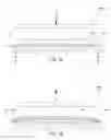
BRIEF DESCRIPTION OF THE DRAWINGSFIG. 1A is a front view of a system schematic for welding and cutting power source components, according to one embodiment of the present subject matter.
FIG. 1B is a front view of a system schematic for welding and cutting power source components, according to one embodiment of the present subject matter.
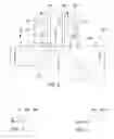
FIG. 2 is a partial bottom view of a cutting and welding tool, according to one embodiment of the present subject matter.
FIG. 3 is a cross section taken at line “3” of FIG. 2, according to one embodiment of the present subject matter.
FIG. 4 is a cross section of a cutting and welding tool, according to one embodiment of the present subject matter.
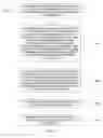
FIG. 5A shows a top and bottom separator sheet and a cross section of a cutting and welding tool, according to one embodiment of the present subject matter.
FIG. 5B shows a welded top and bottom separator sheet, a cross section of a cutting and welding tool, and scrap, according to one embodiment of the present subject matter.
FIG. 6 is a method for cutting and welding separator sheets, according to one embodiment of the present subject matter.
DETAILED DESCRIPTIONThe following detailed description of the present subject matter refers to subject matter in the accompanying drawings which show, by way of illustration, specific aspects and embodiments in which the present subject matter may be practiced. These embodiments are described in sufficient detail to enable those skilled in the art to practice the present subject matter. References to “an”, “one”, or “various” embodiments in this disclosure are not necessarily to the same embodiment, and such references contemplate more than one embodiment. The following detailed description is demonstrative and not to be taken in a limiting sense. The scope of the present subject matter is defined by the appended claims, along with the full scope of legal equivalents to which such claims are entitled.
Self-powered electronic devices are known. For example, self-powered implantable medical devices are now in use for treating a variety of diseases. Implantable pulse generation devices, as well as other types of implantable medical devices, are powered by a battery contained within the housing of the device, in various embodiments. The present subject matter discusses batteries suitable for use in implantable medical devices, as well as other devices requiring self-contained power.
Batteries include various subcomponents. For example, various battery embodiments include opposing anode and cathode plates. These electrode subcomponents, in various embodiments, are isolated by separator. In various embodiments, separator is porous to accommodate electrolyte adapted to sustain ionic transfer between the electrodes. In additional embodiments, the separator includes failsafe subcomponents intended to decrease breakdown by reducing or eliminating ionic transfer. For example, some embodiments include a meltable separator. Various separator embodiments include three layers of porous separator material, such that the center material melts and clogs the pores of the external layers, reducing or eliminating ionic transfer. To ensure that ionic transfer between the anode and the cathode is reduced, in some embodiments, the present subject matter includes separator bags enveloping the battery anode. Bag embodiments cover a large amount of ionic paths between anodes and cathodes. The present subject matter relates to construction of these bags, in various embodiments.
FIG. 1A is a front view of a system schematic for welding and cutting power source components, according to one embodiment of the present subject matter. In various embodiments, the system includes a cutting and welding tool 108, and a stack having a top polymeric separator sheet 104, an anode 106, and a bottom separator sheet 102. Although this embodiment includes an anode, other embodiments can include a cathode. In various embodiments, the bottom 102 and top 104 polymeric sheets include a microporous membrane having a polyethylene layer disposed between two polypropylene layers. Various embodiments include sheets available under the brand name CELGARD, a product of Celgard LLC, of Charlotte, N.C. 28273. Other sheets including additional materials, however, are included within the scope of the present subject matter.
In various embodiments, the battery anode includes lithium. The battery electrode, when viewed from the top, may have any shape, including rectangular shapes, circular shapes, or irregular shapes. Both the shape of the cross section and the top view profile shape of the electrode are provided for explanation, but other shapes are possible. In cathode embodiments, the cathodes include manganese dioxide.
The stack rests on a working surface 110, in various embodiments. The illustration shows that the cutting and welding tool is incident unto the stack. In various embodiments, the present subject matter includes positioning a cutting and welding tool 108 against the top polymeric sheet 104. In alternate embodiments, the cutting and welding tool is fixed to a first static working surface, and a second working surface sandwiches the top and bottom polymeric separator layers and anode between the cutting and welding tool and the second working surface. Additional fixtures are within the scope of the present subject matter.
FIG. 1B is a front view of a system schematic for welding and cutting power source components, according to one embodiment of the present subject matter. The illustration shows components after processing with the cutting and welding tool 108. The illustration shows an anode welded between bottom 102 and top 104 polymeric separator sheets. The components rest on working surface 110. Scrap materials 112, from which the top and bottom separator layers are separated, are also illustrated.
In various embodiments, the cutting and welding tool 108 has an elongate surface with a protrusion extending away from the elongate surface and along the elongate surface. FIG. 2 is a partial bottom view of a cutting and welding tool 108, taken at line “2” of FIG. 1, according to one embodiment of the present subject matter. Visible in the figure is a mounting eyelet 202. Visible are the elongate surface 204 and the protrusion 206. In various embodiments, the cutting and welding tool 108 is a thin ribbon-shaped band. In some embodiments, the cutting and welding tool 108 is substantially rigid. In various embodiments, the cutting and welding tool 108 is metallic.
FIG. 3 is a cross section taken at line “3” of FIG. 2, according to one embodiment of the present subject matter. Illustrated are the protrusion 206 and the elongate surface 204 of the cutting tool 108. In various embodiments, the protrusion is rectangular when viewed from a cross section. FIG. 4 is a cross section of a cutting and welding tool, according to one embodiment of the present subject matter. FIG. 4 demonstrates that the protrusion 406 has a triangular cross section, in various embodiments, bordered by elongate surface 404. In various embodiments, the width of the protrusion is a fraction of the width of the ribbon.
Referring again to FIG. 2, in various embodiments, the cutting and welding tool 108 is shaped for positioning offset from and outside of the perimeter of the battery anode 210. For example, when the anode is disposed between a top and bottom 102 sheet, the cutting surface is shaped such that it can press the sheets together by contacting the top sheet along an area around the anode 210. Contact between the cutting and welding tool 108 and the top sheet occurs proximal the elongate surface 204 and the protrusion 206. In various embodiments, an anode tab portion 209 of the battery anode extends outside the bag. Additional embodiments include alternate anode configurations and shapes also fall within the scope of the present subject matter.
Various embodiments of the present subject matter include applying a pressure and an electrical current to the cutting and welding tool 108 such that top and bottom 102 polymeric separator sheets are welded into a bag. For example, some embodiments define a weld extending around the battery anode proximal the elongate surface 204. The weld may form a circuit around the anode, or may partially surround the anode, in various embodiments. In various embodiments, the battery anode is disposed in the bag. Various embodiments also excise the bag from the top and bottom separator sheets. In various embodiments, the excise occurs proximal protrusion 206.
In various embodiments, the present subject matter uses a cutting and welding tool attached to a thermal impulse sealing fixture. One embodiment uses an HD-0 fixture manufactured by ALINE HEAT SEAL CORPORATION, of Cerritos, Calif. 90703. This fixture includes controllers manufactured by ROPEX of 74321 Bietigheim-Bissingen, Germany. Other fixtures and controllers are within the scope of the present subject matter. In various embodiments, the cutting and welding tool 108 is attached to a thermal impulse sealer at mounting eyelets 202. The duration and intensity of the heat are variable depending on the application, in various embodiments. Additionally, pressure used by the machine is variable and dependent on an application, in various embodiments.
With regard to pressure, in various embodiments, the cutting and welding tool is subjected to a single force vector extending orthogonally into the top sheet. FIGS. 5A-5B show a top 104 and bottom 102 separator sheet and a cross section of a cutting and welding tool 108, according to one embodiment of the present subject matter. In various embodiments, the cutting and welding tool subjects a varied pressure 502 (illustrated with vectors) on the top sheet 104 to which it is incident. The illustrated varied pressure 502 is for explanation only, and other pressure configurations are possible. Additionally, alternate force vector configurations are possible as well. The example illustrates a high pressure area proximal the protrusion 206, and a lower pressure area proximal the elongate surface 204 of the cutting and welding tool 108.
This variable pressure achieves various results. One result is that the low pressure areas are not cut. These areas are welded, in various embodiments. Another result is that an excise occurs proximal the protrusion 206. An excised top and bottom sheet are illustrated in FIG. 5B. The illustration shows scrap 112. Overall, in various embodiments, by heating the cutting and welding tool while providing a force input, a weld and excise are performed.
In various embodiments, because of the combination of pressure and heat energy for cutting and welding, the size and shape of the protrusion is important. As such, various methods are employed to control the distance the protrusion extends away from the elongate surface 204 of the cutting and welding tool 108. In various embodiments, the protrusion is defined by laser cutting the cutting and welding tool. In additional embodiments, the protrusion is defined by machining the cutting and welding tool. In additional embodiments, the protrusion is defined by photochemical etching the cutting and welding tool.
FIG. 6 is a method for cutting and welding separator sheets, according to one embodiment of the present subject matter. In various embodiments, the method includes positioning a bottom and top separator sheet on a working surface 602, with a substantially planar anode disposed therebetween. Additionally, in various embodiments the method includes positioning a cutting tool against the top polymeric sheet 604, the cutting tool having an elongate surface with a protrusion extending away from the elongate surface and along the elongate surface, the elongate surface shaped for positioning offset and outside the perimeter of the anode, wherein the protrusion is defined by laser cutting the cutting tool. In various embodiments the method includes applying a pressure and an electrical current to the cutting tool 606 such that top and bottom polymeric separator sheets are welded into a bag and such that the bag is excised from the top and bottom separator sheets, with the anode disposed in the bag. Some embodiments include stacking the anode and at least one cathode into a battery stack 608. Additionally, some embodiments include disposing the battery stack into a battery case filled with an electrolyte 610.
Application
In various embodiments, the present subject matter includes stacking a battery anode at least partially enveloped by a separator bag into a battery stack. In various embodiments, this includes stacking the battery anode with additional battery anodes. In further embodiments, this includes stacking cathodes with the battery anode.
Various embodiments of the present subject matter dispose the battery stack into a battery case. In various embodiments, the battery case has at least one feedthrough. In some embodiments, a first terminal connected to the battery stack through the at least one feedthrough. Various embodiments additionally fill the battery case with an electrolyte. In various embodiments, the electrolyte is an organic compound.
Various embodiments additionally include positioning the battery case, along with pulse generation electronics connected to the battery case, into a hermetically sealed housing having a first opening sized for passage of the battery case and pulse generation electronics, with a housing lid sealably conformed to the first opening.
Although specific embodiments have been illustrated and described herein, it will be appreciated by those of ordinary skill in the art that any arrangement which is calculated to achieve the same purpose may be substituted for the specific embodiment shown. This application is intended to cover adaptations or variations of the present subject matter. It is to be understood that the above description is intended to be illustrative, and not restrictive. Combinations of the above embodiments, and other embodiments will be apparent to those of skill in the art upon reviewing the above description. The scope of the present subject matter should be determined with reference to the appended claims, along with the full scope of equivalents to which such claims are entitled.
Claims
We claim:1. A method, comprising:
positioning a bottom and top polymeric separator sheet on a working surface, with a substantially planar battery anode disposed therebetween;
positioning a cutting and welding tool against the top polymeric sheet, the cutting and welding tool having an elongate surface with a protrusion extending away from the elongate surface and along the elongate surface, the elongate surface shaped for positioning offset from and outside of the perimeter of the substantially planar battery anode;
applying a pressure and an electrical current to the cutting and welding tool such that top and bottom polymeric separator sheets are welded into a bag and such that the bag is excised from the top and bottom separator sheets, with the substantially planar battery anode disposed in the bag;
stacking the substantially planar battery anode and at least one cathode into a battery stack; and
disposing the battery stack into a battery case having at least one feedthrough, with a first terminal connected to the battery stack through the at least one feedthrough, and with the battery case filled with an electrolyte,
wherein the protrusion is defined by laser cutting the cutting and welding tool.
2. The method of claim 1, further comprising positioning the battery case, along with pulse generation electronics connected to the battery case, in a hermetically sealed housing having a first opening sized for passage of the battery case and pulse generation electronics, with a housing lid sealably conformed to the first opening.
3. The method of claim 1, wherein the top and bottom polymeric separator sheets include a microporous membrane having a polyethylene layer disposed between two polypropylene layers.
4. The method of claim 1, wherein the bag is defined by a weld extending partially around the substantially planar battery anode.
5. The method of claim 4, wherein a tab portion of the substantially planar battery anode extends outside the bag.
6. The method of claim 1, wherein the electrical current is supplied by a thermal impulse sealer.
7. The method of claim 6, wherein the protrusion has a rectangular cross section.
8. A method, comprising:
positioning a bottom and top polymeric separator sheet on a working surface, with a substantially planar battery anode disposed therebetween;
positioning a cutting and welding tool against the top polymeric sheet, the cutting and welding tool having an elongate surface with a protrusion extending away from the elongate surface and along the elongate surface, the elongate surface shaped for positioning offset from and outside of the perimeter of the substantially planar battery anode;
applying a pressure and an electrical current to the cutting and welding tool such that top and bottom polymeric separator sheets are welded into a bag and such that the bag is excised from the top and bottom separator sheets, with the substantially planar battery anode disposed in the bag;
stacking the substantially planar battery anode and at least one cathode into a battery stack; and
disposing the battery stack into a battery case having at least one feedthrough, with a first terminal connected to the battery stack through the at least one feedthrough, and with the battery case filled with an electrolyte,
wherein the protrusion is defined by machining the cutting and welding tool.
9. The method of claim 8, further comprising positioning the battery case, along with pulse generation electronics connected to the battery case, in a hermetically sealed housing having a first opening sized for passage of the battery case and pulse generation electronics, with a housing lid sealably conformed to the first opening.
10. The method of claim 8, wherein the top and bottom polymeric separator sheets include a microporous membrane having a polyethylene layer disposed between two polypropylene layers.
11. The method of claim 8, wherein the bag is defined by a weld extending partially around the substantially planar battery anode.
12. The method of claim 11, wherein a tab portion of the substantially planar battery anode extends outside the bag.
13. The method of claim 8, wherein the electrical current is supplied by a thermal impulse sealer.
14. The method of claim 13, wherein the protrusion has a rectangular cross section.
15. A method, comprising:
positioning a bottom and top polymeric separator sheet on a working surface, with a substantially planar battery anode disposed therebetween;
positioning a cutting and welding tool against the top polymeric sheet, the cutting and welding tool having an elongate surface with a protrusion extending away from the elongate surface and along the elongate surface, the elongate surface shaped for positioning offset from and outside of the perimeter of the substantially planar battery anode;
applying a pressure and an electrical current to the cutting and welding tool such that top and bottom polymeric separator sheets are welded into a bag and such that the bag is excised from the top and bottom separator sheets, with the substantially planar battery anode disposed in the bag;
stacking the substantially planar battery anode and at least one cathode into a battery stack; and
disposing the battery stack into a battery case having at least one feedthrough, with a first terminal connected to the battery stack through the at least one feedthrough, and with the battery case filled with an electrolyte,
wherein the protrusion is defined by photochemical etching the cutting and welding tool.
16. The method of claim 15, further comprising positioning the battery case, along with pulse generation electronics connected to the battery case, in a hermetically sealed housing having a first opening sized for passage of the battery case and pulse generation electronics, with a housing lid sealably conformed to the first opening.
17. The method of claim 15, wherein the top and bottom polymeric separator sheets include a microporous membrane having a polyethylene layer disposed between two polypropylene layers.
18. The method of claim 15, wherein the bag is defined by a weld extending partially around the substantially planar battery anode.
19. The method of claim 18, wherein a tab portion of the substantially planar battery anode extends outside the bag.
20. The method of claim 15, wherein the electrical current is supplied by a thermal impulse sealer.
21. The method of claim 20, wherein the protrusion has a rectangular cross section.
Images & Drawings included:


Sources:
- United States Patent and Trademark Office - verify current appl. status at the USPTO↗
Similar patent applications:
Recent applications in this class:
- » 20250187274 2025-06-12
INSERT STAKING DEVICE AND METHOD - » 20250100230 2025-03-27
Weld Seam, Method and Device for Connecting Plastics Films by Thermal Joining, and Use of a Blow-Forging Press - » 20250026084 2025-01-23
METHOD AND APPARATUS FOR JOINING THERMOPLASTIC COMPOSITE COMPONENTS - » 20240001624 2024-01-04
Continuous motion impulse heat sealing of film material - » 20230294366 2023-09-21
PULSE WELDING METHOD AND WELDING TOOL FOR PULSE WELDING FOR A MEDICAL PACK FORMED AS A BAG - » 20230166458 2023-06-01
Fiber-reinforced composite laminate for use in electromagnetic welding and method of electromagnetic welding of molded parts of said laminates - » 20220266538 2022-08-25
Continuous motion impulse heat sealing of film material - » 20210331424 2021-10-28
Impulse welding bar with non-stick coating - » 20210299971 2021-09-30
Contour-forming welding tool for pulse welding and contour-forming pulse welding method for a medical pack formed as a bag - » 20210178704 2021-06-17
Rotary impulse sealer
Recent applications for this Assignee:
- » 20250276189 2025-09-04
IMPLANTABLE MEDICAL DEVICE WITH FEEDTHROUGH ANTENNA GROUND STRUCTURE - » 20250082930 2025-03-13
DELIVERY DEVICES AND METHODS FOR LEADLESS CARDIAC DEVICES - » 20250050117 2025-02-13
IMPLANTABLE MEDICAL DEVICE WITH PRESSURE SENSOR - » 20250025700 2025-01-23
REMOTE MONITORING OF CARDIAC IMD SIGNAL QUALITY - » 20240416114 2024-12-19
IMPLANTABLE MEDICAL DEVICES AND METHODS FOR MAKING AND DELIVERING IMPLANTABLE MEDICAL DEVICES - » 20240325764 2024-10-03
IMPLANTABLE MEDICAL DEVICE WITH FLEX CIRCUIT - » 20240306310 2024-09-12
IMPLANTABLE MEDICAL DEVICE CASE FIT WITH SELECTIVE ENCAPSULATION - » 20240290566 2024-08-29
IMPLANTABLE MEDICAL DEVICE SELECTIVE ENCAPSULATION - » 20240261581 2024-08-08
IMPLANTABLE MEDICAL DEVICE WITH MOTION DAMPING LAYER - » 20240261579 2024-08-08
IMPLANTABLE MEDICAL DEVICE WITH HYDROGEN GETTER