Arrangement for inspecting objects, especially masks in microlithography
US20060262306A1
2006-11-23
10/554,048
2004-04-20
✅ Patent granted
US 7,525,115 B2
2009-04-28
WO; PCT/EP2004/004161; 20040420
WO; WO2004/095136; 20041104
David P Porta | Faye Boosalis
2024-06-23
Abstract:
Apparatus for inspecting objects especially masks in microlithography that are disposed in a vacuum chamber. The apparatus includes a converter for converting illuminating radiation emitted from the object into a radiation of a higher wavelength. A sensor for recording images is disposed outside the vacuum chamber and arranged as an optical interface from the vacuum chamber to the sensor of the converter or at least one part of an image lens is arranged as a window in the vacuum chamber.
Inventors:
- Hans-Juergen Dobschal 50 🇩🇪 Kleinromstedt, Germany
- Thomas Scheruebl 14 🇩🇪 Jena, Germany
- Wolfgang Harnisch 11 🇩🇪 Lehesten, Germany
- Nobert Rosenkranz 1 🇩🇪 Reichenbach, Germany
- Ralph Semmler 2 🇩🇪 Jena, Germany
Assignee:
- CARL ZEISS SMS GMBH 60 🇩🇪 Jena, Germany
Interested in similar patents?
Get notified when new applications in this technology area are published.
Classification:
B82Y10/00 » CPC main
Nanotechnology for information processing, storage or transmission, e.g. quantum computing or single electron logic
B82Y40/00 » CPC further
Manufacture or treatment of nanostructures
G01N21/956 » CPC further
Investigating or analysing materials by the use of optical means, i.e. using sub-millimetre waves, infrared, visible or ultraviolet light; Systems specially adapted for particular applications; Investigating the presence of flaws or contamination characterised by the material or shape of the object to be examined Inspecting patterns on the surface of objects
G03F1/24 » CPC further
Originals for photomechanical production of textured or patterned surfaces, e.g., masks, photo-masks, reticles; Mask blanks or pellicles therefor; Containers specially adapted therefor; Preparation thereof; Masks or mask blanks for imaging by radiation of 100nm or shorter wavelength, e.g. X-ray masks, extreme ultra-violet [EUV] masks; Preparation thereof Reflection masks; Preparation thereof
G03F1/84 » CPC further
Originals for photomechanical production of textured or patterned surfaces, e.g., masks, photo-masks, reticles; Mask blanks or pellicles therefor; Containers specially adapted therefor; Preparation thereof; Preparation processes not covered by groups -; Auxiliary processes, e.g. cleaning or inspecting Inspecting
G01N21/00 IPC
Investigating or analysing materials by the use of optical means, i.e. using sub-millimetre waves, infrared, visible or ultraviolet light
G01N23/04 IPC
Investigating or analysing materials by the use of wave or particle radiation, e.g. X-rays or neutrons, not covered by groups – , or by transmitting the radiation through the material and forming images of the material
Description
CROSS REFERENCE TO RELATED APPLICATIONSThe present patent application is a nationalization of International Application No. PCT/EP2004/004161, filed Apr. 20, 2004, which is based on, and claims priority from, German Application No. DE 103 18 560.7, filed Apr. 24, 2003, both of which are incorporated herein by reference in their entireties.
FIELD OF THE INVENTIONThis invention relates to the field of Microlithography and to devices for inspecting objects that are disposed in a vacuum chamber.
BACKGROUND OF THE INVENTIONIn order to observe objects or images of objects disposed in vacuum chambers, it is necessary to either insert the observation lens and the sensor (camera) into the vacuum chamber or to observe the objects or images through a vacuum window.
This is particularly required in the case of images using extreme ultraviolet radiation (EUV) if this radiation is converted using scintillators into radiation of a different wavelength and then reproduced on the sensor using additional optics such as described in U.S. Pat. No. 5,498,923.
If the sensor is disposed in the interior of the vacuum chamber, this leads to gas emission of, for example, siloxanes or hydrocarbons from the sensor. This poses a high hazard of contamination of the devices disposed in the vacuum chamber. Optical elements that are exposed to radiation that is rich in energy, particularly EUV radiation, are especially at risk.
If the sensor is disposed outside this vacuum chamber, the radiation used for the image must be guided through a vacuum window onto the sensor. As a result of the window in this case, limitations arise with respect to the quality of the optical images and the usable aperture of the imaging optics.
SUMMARY OF THE INVENTIONThis problem of the prior art is solved according to the present invention, in that the scintillator itself forms the window or configures the imaging optics disposed in front of the sensor in such a manner that the imaging optics or a part of them are used to form the vacuum window.
Different configurations are possible depending on the respective tasks:
a) The imaging lens is vacuum-tight and forms the actual window.
b) The scintillator forms the vacuum window. The vacuum window can be designed advantageously such that it can be replaced, if the scintillator starts to age.
c) A part of the lens forms the vacuum window. Here, it is particularly advantageous to configure the first lens of the imaging optics from the source of radiation as the vacuum window because then the remaining parts of the lens are not exposed to the vacuum. Furthermore, the first lens can be permanently arranged in the vacuum chamber and the remainder of the lens can be interchangeable in order to change the imaging conditions, for example for recording an overview image by adding other lens groups.
Using all the specified options, it is possible to arrange the actual sensor that represents a high risk of emissions and contamination outside the vacuum chamber and yet achieve a superior optical imaging quality.
BRIEF DESCRIPTION OF THE DRAWINGSFIG. 1 is a schematic drawing of an inspection apparatus embodying the subject invention.
FIG. 2 is a schematic diagram of a lens system forming part of the subject invention of FIG. 1.
DETAILED DESCRIPTION OF THE PREFERRED EMBODIMENTSIn describing preferred embodiments of the present invention illustrated in the drawings, specific terminology is employed for the sake of clarity. However, the invention is not intended to be limited to the specific terminology so selected, and it is to be understood that each specific element includes all technical equivalents that operate in a similar manner to accomplish a similar purpose.
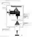
The present invention is explained more fully on the basis of FIG. 1.
The object field OF illuminated using an EUV source of light LQ via illuminating optics EUVBO is reproduced on a scintillator S by means of EUV optics EUVO. The scintillator converts the image of the EUV wavelength range into an image of a long-wave range, which is then reproduced on the sensor using an image lens O (i.e. micro lens). In doing so, the imaging lens/the scintillator is used according to the invention in one of the configurations described above.
The lens O is illustrated schematically. A first optical element can form the window, which is then followed by other lens elements that are arranged outside the vacuum chamber VK and are not illustrated here.
FIG. 2 illustrates an optical example for the lens O. The lens illustrated is advantageously a cement-free hybrid lens as has been described in detail in DE 10130212 A1. Its advantage is the low material expenditure involved and better optical quality. The use of a diffractive element DOE increases refraction and has an achromatising effect.
The first optical element F1/F2 and also e.g. the DOE F9/F10 can be the window of the vacuum chamber here.
Data regarding the hybrid lens (mm)
| Surface | Radius | Thickness | Material | |
| F1 | unlimited | |||
| 1.000 | Q1 (synthetic quartz) | |||
| F2 | Unlimited | |||
| 0.3028 | Air | |||
| F3 | −2.744 | |||
| 2.9773 | Bk10 | |||
| F4 | −3.116 | |||
| 0.0200 | Air | |||
| F5 | −9.911 | |||
| 2.5723 | Bk7 | |||
| F6 | −5.292 | |||
| 0.0500 | Air | |||
| F7 | 19.699 | |||
| 2.9207 | Bk7 | |||
| F8 | −11.828 | |||
| 0.0500 | Air | |||
| F9 | Unlimited | |||
| 2.0033 | Bk7 | |||
| F10 | Unlimited | |||
| F11 | 23.072 | |||
| 2.000 | Nsf6 | |||
| F12 | 7.541 | |||
| 0.5624 | Air | |||
| F13 | 9.051 | |||
| 3.2297 | Psk53a | |||
| F14 | −15.148 | |||
| 15.2701 | Air | |||
| F15 | −4.369 | |||
| 0.500 | Ssk2 | |||
| F16 | −117.556 | |||
. . . etc. to the tube lens (not illustrated)
It is to be understood that the present invention is not limited to the illustrated embodiments described herein. Modifications and variations of the above-described embodiments of the present invention are possible, as appreciated by those skilled in the art in light of the above teachings. It is therefore to be understood that, within the scope of the appended claims and their equivalents, the invention may be practiced otherwise than as specifically described.
Claims
What is claimed is:1. Apparatus for inspecting an object, especially a mask in microlithography, that is disposed in a vacuum chamber, the apparatus comprising:
a converter for converting illuminating radiation emitted from the object into a radiation of a higher wavelength;
a sensor for recording images, the sensor being disposed outside the vacuum chamber; and
an optical interface from the vacuum chamber, the optical interface including an image lens wherein at least one part of the image lens is arranged as a vacuum window in the vacuum chamber.
2. The apparatus of claim 1, where the image lens is a cement-free hybrid lens having at least one diffractive optical element.
3. The apparatus of claim 2, wherein the image lens comprises:
a first lens group having a positive refraction power; and
a second lens group having a negative refraction power, the second lens group being arranged downstream from the first lens group and the first lens group containing the diffractive optical element.
4. The apparatus of claim 1, wherein the converter comprises a scintillator.
5. Apparatus for inspecting an object, especially a mask in microlithography, that is disposed in a vacuum chamber having a vacuum window, the apparatus comprising:
a converter for converting illuminating radiation emitted from the object into a radiation of a higher wavelength;
a sensor for recording images, the sensor being disposed outside the vacuum chamber; and
an optical interface from the vacuum chamber, the optical interface including the vacuum window in the vacuum chamber.
6. The apparatus of claim 5, wherein the optical interface has an imaging lens that is vacuum-tight and forms the vacuum window.
7. The apparatus of claim 5, wherein the vacuum window is defined by a scintillator.
8. The apparatus of claim 5, wherein a part of a lens defined in the optical interface defines the vacuum window.
Images & Drawings included:


Sources:
- United States Patent and Trademark Office - verify current appl. status at the USPTO↗
Recent applications in this class:
- » 20210188629 2021-06-24
Method of ono integration into logic CMOS flow - » 20200385266 2020-12-10
Quantum shift register structures - » 20200369517 2020-11-26
Amplitude, frequency, and phase modulated entangling gates for trapped-ion quantum computers - » 20200307995 2020-10-01
Machine Learning Processor Employing a Monolithically Integrated Memory System - » 20200109049 2020-04-09
Nanowire arrays for trace vapor preconcentration - » 20200079648 2020-03-12
Syndrome of degraded quantum redundancy coded states - » 20190337800 2019-11-07
Semiconductor arrangement with one or more semiconductor columns - » 20190194016 2019-06-27
QUANTUM COMPUTING ASSEMBLIES - » 20180237294 2018-08-23
Nanowire arrays for trace vapor preconcentration - » 20180002172 2018-01-04
Semiconductor arrangement with one or more semiconductor columns
Recent applications for this Assignee:
- » 20140369592 2014-12-18
Method for establishing distortion properties of an optical system in a microlithographic measurement system - » 20140254915 2014-09-11
Method for analyzing a photomask - » 20140036243 2014-02-06
Method and apparatus for correcting errors on a wafer processed by a photolithographic mask - » 20140027512 2014-01-30
Apparatus and method for investigating an object - » 20140007306 2014-01-02
Apparatus and method for analyzing and modifying a specimen surface - » 20130321609 2013-12-05
Microscope and method for characterizing structures on an object - » 20130308125 2013-11-21
Method for characterizing a structure on a mask and device for carrying out said method - » 20130293962 2013-11-07
Irradiation module for a measuring apparatus - » 20130258342 2013-10-03
Temperature sensor and method for measuring a temperature change - » 20130209926 2013-08-15
Controllable transmission and phase compensation of transparent material