Method and apparatus for improved channel maintenance signaling
US20060268788A1
2006-11-30
11/411,753
2006-04-25
✅ Patent granted
US 7,492,752 B2
2009-02-17
-
-
Kamran Afshar
2027-07-10
Abstract:
Various embodiments are described to address the need for channel maintenance/channel quality signaling that can better utilize reverse link capacity and conserve battery life. Generally expressed, a remote unit (101) enters (403) a high-rate-channel-maintenance mode in which it transmits channel maintenance signaling. When a low-rate condition is met (405), the remote unit enters (407) a low-rate-channel-maintenance mode in which it transmits channel maintenance signaling at either a lower rate or a lower transmit power than when in the high-rate-channel-maintenance mode. Then when a high-rate condition is met (409), the remote unit reenters the high-rate-channel-maintenance mode.
Inventors:
- Joseph R. Schumacher 10 🇺🇸 Glen Ellyn, IL, United States
- JOHN M. HARRIS 129 🇺🇸 CHICAGO, IL, United States
- Vijay G. Subramanian 7 🇺🇸 Chicago, IL, United States
Assignee:
- MOTOROLA, INC. 4,815 🇺🇸 Schaumburg, IL, United States
Interested in similar patents?
Get notified when new applications in this technology area are published.
Classification:
H04W52/60 » CPC main
Power management, e.g. TPC [Transmission Power Control], power saving or power classes; TPC; Signalisation aspects of the TPC commands, e.g. frame structure using different transmission rates for TPC commands
H04W52/267 » CPC further
Power management, e.g. TPC [Transmission Power Control], power saving or power classes; TPC; TPC being performed according to specific parameters using transmission rate or quality of service QoS [Quality of Service] taking into account the information rate
H04W52/325 » CPC further
Power management, e.g. TPC [Transmission Power Control], power saving or power classes; TPC using constraints in the total amount of available transmission power; TPC of broadcast or control channels Power control of control or pilot channels
H04B17/24 » CPC further
Monitoring; Testing of receivers with feedback of measurements to the transmitter
H04W4/06 » CPC further
Services specially adapted for wireless communication networks; Facilities therefor Selective distribution of broadcast services, e.g. multimedia broadcast multicast service [MBMS]; Services to user groups; One-way selective calling services
H04W28/22 » CPC further
Network traffic or resource management; Central resource management; Negotiation of resources or communication parameters, e.g. negotiating bandwidth or QoS [Quality of Service]; Negotiating wireless communication parameters Negotiating communication rate
H04W36/00 » CPC further
Hand-off or reselection arrangements
H04W48/08 » CPC further
Access restriction ; Network selection; Access point selection Access restriction or access information delivery, e.g. discovery data delivery
H04W52/0216 » CPC further
Power management, e.g. TPC [Transmission Power Control], power saving or power classes; Power saving arrangements in terminal devices managed by the network, e.g. network or access point is master and terminal is slave using a pre-established activity schedule, e.g. traffic indication frame
H04W52/0245 » CPC further
Power management, e.g. TPC [Transmission Power Control], power saving or power classes; Power saving arrangements in terminal devices using monitoring of external events, e.g. the presence of a signal according to signal strength
H04W76/20 » CPC further
Connection management Manipulation of established connections
Y02D30/70 » CPC further
Reducing energy consumption in communication networks in wireless communication networks
Y02D30/70 » CPC further
Reducing energy consumption in communication networks in wireless communication networks
H04B7/216 IPC
Radio transmission systems, i.e. using radiation field; Relay systems; Active relay systems; Multiple access Code division or spread-spectrum multiple access [CDMA, SSMA]
Description
REFERENCE(S) TO RELATED APPLICATION(S)The present application claims priority from provisional application, Ser. No. 60/684428, entitled “METHOD AND APPARATUS FOR IMPROVED CHANNEL MAINTENANCE SIGNALING,” filed May 25, 2005, which is commonly owned and incorporated herein by reference in its entirety.
FIELD OF THE INVENTIONThe present invention relates generally to wireless communication systems and, in particular, to an apparatus and method for improved channel quality reporting.
BACKGROUND OF THE INVENTIONIn existing wireless access technologies such as IEEE 802.16, High Speed Downlink Packet Access (HSDPA), and High Rate Packet Data (HRPD), also known as 1xEV-DO or IS-856, the reverse link transmission of channel quality indications, for example, consume a substantial amount of the available reverse link capacity. In addition, the transmission of CQI (Channel Quality Indicator), DRC (Data Rate Control), and an HS-DPCCH (High Speed Downlink Packet Control Channel), in respective 802.16, HRPD, and HSDPA systems reduces remote unit battery life.
Existing technology addresses these issues by using explicit access network (AN) signaling to toggle remote unit CQI/DRC transmissions. Thus, the AN can thereby enable the remote units to stop transmitting channel quality information when the AN does not need the information. For example, a remote unit may be in a CQI/DRC gating mode in which channel quality information is transmitted on the reverse link in periodic bursts. The AN may signal the remote unit to transition to a CQI/DRC DTX (discontinuous transmission) mode in which the transmission of channel quality information is suspended. Then, when the channel quality information is needed again, the AN signals the remote unit to return to CQI/DRC gating mode. However, such AN signaling to control the remote unit transmit mode also creates additional overhead signaling that itself can become burdensome. This signaling can also create delays by requiring the AN to first signal the remote unit to resume CQI/DRC transmission before the AN proceeds to transmit data to the remote unit.
Therefore, a need exists for an improved apparatus and method for channel maintenance/quality signaling that can better utilize reverse link capacity and conserve battery life.
BRIEF DESCRIPTION OF THE DRAWINGSFIG. 1 is a block diagram depiction of a wireless communication system in accordance with multiple embodiments of the present invention.
FIG. 2 is a block diagram depiction of exemplary signaling timelines that compare prior art signaling with signaling in accordance with multiple embodiments of the present invention.
FIGS. 3A-3G, considered together (hereinafter “FIG. 3”), form a series of exemplary signaling timelines that depict channel maintenance signaling in which different conditions are used to enter a low-rate-channel-maintenance mode, in accordance with multiple embodiments of the present invention.
FIG. 4 is a logic flow diagram of functionality performed by a remote unit in accordance with multiple embodiments of the present invention.
FIG. 5 is a logic flow diagram of functionality performed by an access network (AN) in accordance with multiple embodiments of the present invention.
Specific embodiments of the present invention are disclosed below with reference to FIGS. 1-5. Both the description and the illustrations have been drafted with the intent to enhance understanding. For example, the dimensions of some of the figure elements may be exaggerated relative to other elements, and well-known elements that are beneficial or even necessary to a commercially successful implementation may not be depicted so that a less obstructed and a more clear presentation of embodiments may be achieved. Simplicity and clarity in both illustration and description are sought to effectively enable a person of skill in the art to make, use, and best practice the present invention in view of what is already known in the art. One of skill in the art will appreciate that various modifications and changes may be made to the specific embodiments described below without departing from the spirit and scope of the present invention. Thus, the specification and drawings are to be regarded as illustrative and exemplary rather than restrictive or all-encompassing, and all such modifications to the specific embodiments described below are intended to be included within the scope of the present invention.
DETAILED DESCRIPTION OF THE EMBODIMENTSVarious embodiments are described to address the need for channel maintenance/channel quality signaling that can better utilize reverse link capacity and conserve battery life. Generally expressed, a remote unit enters a high-rate-channel-maintenance mode in which it transmits channel maintenance signaling. When a low-rate condition is met, the remote unit enters a low-rate-channel-maintenance mode in which it transmits channel maintenance signaling at either a lower rate or a lower transmit power than when in the high-rate-channel-maintenance mode. Then when a high-rate condition is met, the remote unit reenters the high-rate-channel-maintenance mode.
The disclosed embodiments can be more fully understood with reference to FIGS. 1-5. FIG. 1 is a block diagram depiction of a wireless communication system 100 in accordance with multiple embodiments of the present invention. At present, standards bodies such as OMA (Open Mobile Alliance), 3GPP (3rd Generation Partnership Project), 3GPP2 (3rd Generation Partnership Project 2) and IEEE (Institute of Electrical and Electronics Engineers) 802 are developing standards specifications for wireless telecommunications systems. (These groups may be contacted via http://www.openmobilealliance.com, http://www.3gpp.org/, http://www.3gpp2.com/ and http://www.ieee802.org/, respectively.) Communication system 100 represents a system having an access network that may be based on different wireless technologies. For example, the description that follows will assume that AN 121 is IEEE 802.XX-based, employing wireless technologies such as IEEE's 802.11, 802.16, or 802.20. Being 802.XX-based, AN 121 is additionally modified to implement embodiments of the present invention.
However, alternative embodiments of the present invention may be implemented in communication systems that employ other or additional technologies such as, but not limited to, those described in the 3GPP2 specifications (e.g., CDMA 2000 or High Rate Packet Data (HRPD), which is also known as 1xEV-DO), those described in the 3GPP specifications (e.g., GSM, GPRS, EDGE, W-CDMA, UTRAN, FOMA, UMTS, HSDPA, and HSUPA), those described in the IS-95 (CDMA) specification, 1xEV-DV technologies, and integrated dispatch enhanced network technologies.
More specifically, communication system 100 comprises remote unit 101, access network (AN) 121, and packet network 151. Those skilled in the art will recognize that FIG. 1 does not depict all of the network equipment necessary for system 100 to operate but only those system components and logical entities particularly relevant to the description of embodiments herein. For example, ANs are known to comprise one or more devices such as WLAN (wireless local area network) stations (which include access points (APs), AP controllers/switches, and/or WLAN switches), base transceiver stations (BTSs), base site controllers (BSCs) (which include selection and distribution units (SDUs)), packet control functions (PCFs), packet control units (PCUs), and/or radio network controllers (RNCs). However, none of these devices are specifically shown in FIG. 1.
Instead, AN 121 is depicted in FIG. 1 as comprising processing unit 125, network interface 127, and transceiver 123. In general, components such as processing units, network interfaces, and transceivers are well-known. For example, AN processing units are known to comprise basic components such as, but not limited to, microprocessors, microcontrollers, memory devices, application-specific integrated circuits (ASICs), and/or logic circuitry. Such components are typically adapted to implement algorithms and/or protocols that have been expressed using high-level design languages or descriptions, expressed using computer instructions, expressed using messaging flow diagrams, and/or expressed using logic flow diagrams.
Thus, given an algorithm, a logic flow, a messaging/signaling flow, and/or a protocol specification, those skilled in the art are aware of the many design and development techniques available to implement an AN processing unit that performs the given logic. Therefore, AN 121 represents a known AN that has been adapted, in accordance with the description herein, to implement multiple embodiments of the present invention. Furthermore, those skilled in the art will recognize that aspects of the present invention may be implemented in and across various physical components and none are necessarily limited to single platform implementations. For example, the AN aspect of the present invention may be implemented in any of the AN devices listed above or distributed across such components.
AN 121 uses wireless interfaces 111 and 113 for communication with remote unit 101. Since, for the purpose of illustration, AN 121 is IEEE 802.XX-based, wireless interfaces 111 and 113 correspond to a forward link and a reverse link, respectively, each link comprising a group of IEEE 802.XX-based channels suitably modified to implement embodiments of the present invention.
Remote unit platforms are known to refer to a wide variety of consumer electronic platforms such as, but not limited to, mobile stations (MSs), mobile nodes (MNs), access terminals (ATs), terminal equipment, gaming devices, personal computers, and personal digital assistants (PDAs). In particular, remote unit 101 comprises processing unit 102, transceiver 103, a keypad (not shown), a speaker (not shown), a microphone (not shown), and a display (not shown). Processing units, transceivers, keypads, speakers, microphones, and displays as used in remote units are all well-known in the art.
For example, remote unit processing units are known to comprise basic components such as, but not limited to, microprocessors, digital signal processors (DSPs), microcontrollers, memory devices, application-specific integrated circuits (ASICs), and/or logic circuitry. Such remote unit components are typically adapted to implement algorithms and/or protocols that have been expressed using high-level design languages or descriptions, expressed using computer instructions, expressed using messaging/signaling flow diagrams, and/or expressed using logic flow diagrams. Thus, given an algorithm, a logic flow, a messaging/signaling flow, a call flow, and/or a protocol specification, those skilled in the art are aware of the many design and development techniques available to implement user equipment that performs the given logic. Therefore, remote unit 101 represents a known remote unit that has been adapted, in accordance with the description herein, to implement embodiments of the present invention.
A discussion of certain embodiments in greater detail follows first with reference to FIG. 2. FIG. 2 is a block diagram depiction of exemplary signaling timelines that compare prior art signaling with signaling in accordance with multiple embodiments of the present invention. Prior art techniques for providing channel quality feedback, such as CQI or DRC (data rate control) signaling, via the reverse link are not optimized for uplink-transfer-only situations. Such uplink-only transmission intervals often occur when providing services such as PTT (push-to-talk)/dispatch half duplex calling, for example. A PTT application on a remote unit is aware that it is very unlikely to receive any packets on the forward link for a sustained interval while it is the PTT speaker. In this case, the remote unit would prefer to use channel quality feedback DTX (discontinuous transmission) mode in order to conserve battery life and reduce reverse link interference.
However, it is possible that an unexpected packet will arrive at the infrastructure for transmission to the remote unit via the forward link during this PTT speaker interval. In order to address this possibility, the remote unit and infrastructure should agree upon and use a policy whereby the remote unit will periodically switch to a channel quality feedback gating mode, in which CQI/DRC gated transmission occurs, for a fixed interval of time. In between these intervals the remote unit will use the channel quality feedback DTX mode. If any unexpected packets show up during this substantially uplink-transfer-only interval then the infrastructure can queue the packets until the target remote unit's next agreed-upon channel quality feedback gating mode interval. This operation is depicted in signaling timeline 200. In addition, if the remote unit does begin receiving packets, the remote unit can then be instructed to resume its more continuous gated CQI/DRC transmission.
In addition, prior art techniques for channel quality feedback gating are also not optimized for remote units that are receiving a streaming service. During such streaming services, the infrastructure will occasionally receive a packet destined for the remote unit. Current, standardized channel quality feedback policies require an explicit message when switching between channel quality feedback gating and channel quality feedback DTX modes. An inordinate number of prior art messages would thus be required to toggle the channel quality feedback gating mode before and after each streamed packet. Therefore, the system is unable to fully exploit all the intervals in which the remote unit could otherwise use channel quality feedback DTX mode.
To address this problem, certain embodiments of the present invention provide a single message instructing the remote unit to periodically switch to channel quality feedback gating mode for a predefined interval and to use channel quality feedback DTX mode in between these predefined intervals. In addition, the gated transmission interval can be defined as ending after the remote unit fails to receive any forward traffic channel packets for a given period of time. In this way, the channel quality feedback gating mode can extend longer as needed but without requiring a specific message to change the channel quality feedback mode for each packet. Some of these embodiments are depicted in signaling timeline 250.
More generally, many embodiments of the present invention may be considered with reference to FIGS. 3 and 4. FIG. 4 is a logic flow diagram of functionality performed by a remote unit in accordance with multiple embodiments of the present invention. Logic flow 400 begins (401) when the remote unit enters (403) a high-rate-channel-maintenance mode in which the remote unit transmits channel maintenance signaling. The channel maintenance signaling referred to may include one or more types of signaling such as channel quality indication (CQI) signaling, power control signaling, reverse dedicated pilot signaling, forward dedicated pilot signaling, and ACK/NACK signaling.
The remote unit remains in the high-rate-channel-maintenance mode until a low-rate condition is satisfied (405). The remote unit then enters (407) a low-rate-channel-maintenance mode in which the remote unit transmits the channel maintenance signaling at either a lower rate or a lower transmit power as compared to its channel maintenance signaling when in the high-rate-channel-maintenance mode. For example, if the channel maintenance signaling includes power control, then the remote unit may send the power control bits at a lower rate while in the low-rate-channel-maintenance mode than when it was previously in the high-rate-channel-maintenance mode. Likewise, for the case where the channel maintenance signaling includes channel quality indication signaling (such as DRC), the remote unit may send the channel quality indications at a lower rate than when the remote unit was in the high-rate-channel-maintenance mode.
The transmission of channel maintenance signaling at a lower rate may even include suspending the channel maintenance signaling altogether. In one example, both the channel quality indication signaling and the reverse dedicated pilot may be suspended in the low-rate-channel-maintenance mode. In another example, when the remote unit enters the low-rate-channel-maintenance mode, transmission of the reverse dedicated pilot is unchanged while the channel quality indication signaling is suspended.
The low-rate condition that triggers the remote unit to enter the low-rate-channel-maintenance mode can be one (or a combination) of many different conditions depending on the particular service being supported or the embodiment implemented. Thus, the low-rate condition may be satisfied by any one of a number of component conditions being satisfied or alternatively by all of a combination of component conditions being satisfied. FIG. 3 includes a series of exemplary signaling timelines that depict channel maintenance signaling in which different conditions are used to enter a low-rate-channel-maintenance mode, in accordance with multiple embodiments of the present invention. For example, signaling timeline 300 depicts CQI signaling by the remote unit in the high-rate-channel-maintenance mode for a period d. As depicted, transmission of the CQI signaling occurs in a gated fashion (having a period p) rather than in a continuous transmit fashion.
Signaling timeline 310 depicts CQI signaling in which the low-rate condition requires a pre-established period of time B to elapse after the remote unit last entered the high-rate-channel-maintenance mode. Signaling timeline 320 depicts CQI signaling in which the low-rate condition requires a pre-established period of time to elapse after link activity completes on a forward link associated with the channel maintenance signaling. Signaling timeline 330 depicts CQI signaling in which the low-rate condition requires a pre-established number of packets (one packet, e.g.) to first be received via the forward link. Signaling timeline 340 depicts CQI signaling in which the low-rate condition requires a pre-established number of bytes (500 bytes, e.g.) to first be received via the forward link. Similar to the examples depicted in timelines 330 and 340, but not additionally depicted, are the cases in which the low-rate condition requires a pre-established number of packets or bytes to first be successfully transmitted via a reverse link. Signaling timeline 350 depicts CQI signaling in which the low-rate condition requires a cumulative number of packets or bytes to first be received via the forward link that total the sum of a pre-established number (one packet, e.g.) for each high-rate initiation point that has passed. Finally, signaling timeline 360 depicts CQI signaling in which the low-rate condition requires a non-cumulative, pre-established number (one packet, e.g.) to first be received via the forward link after any high-rate initiation point.
Thus, the remote unit remains in the high-rate-channel-maintenance mode until a low-rate condition such as one or more of the conditions described above is satisfied (405). The remote unit then enters (407) the low-rate-channel-maintenance mode in which the remote unit transmits the channel maintenance signaling at either a lower rate or a lower transmit power as compared to its channel maintenance signaling when in the high-rate-channel-maintenance mode.
The remote unit remains in the low-rate-channel-maintenance mode until a high-rate condition is satisfied (409). When it is, the remote unit reenters (403) the high-rate-channel-maintenance mode from the low-rate-channel-maintenance mode. The high-rate condition that triggers the remote unit to reenter the high-rate-channel-maintenance mode can be one (or a combination) of many different conditions depending on the particular service being supported or the embodiment implemented. Thus, the high-rate condition may be satisfied by any one of a number of component conditions being satisfied or alternatively by all of a combination of component conditions being satisfied.
For example, the exemplary signaling timelines of FIG. 3 depict channel maintenance signaling in which the high-rate condition requires the time remaining until a next periodic, high-rate initiation point after the remote unit enters the low-rate-channel-maintenance mode to elapse. In other words the arrival of the next periodic initiation point satisfies the condition for reentering the high-rate-channel-maintenance mode. Another high-rate condition may require the remote unit to receive a request from the AN to reenter before reentering the high-rate-channel-maintenance mode. Yet another high-rate condition may be satisfied when the remote unit detects that handoff conditions are present for the remote unit. Finally, another high-rate condition may be satisfied when the remote unit begins receiving data via a forward link associated with the channel maintenance signaling.
In view of the more general description above, operation of certain specific embodiments will be described below with reference first to FIG. 1. In embodiments in which the network sets the channel maintenance signaling policy for the remote unit, the AN may transmit a policy establishment message to the remote unit that includes parameters that define how the different signaling modes should be used. For example, AN processing unit 125 sends an indication to remote unit 101, via transceiver 123 and wireless interface 111, that remote unit 101 should transition from a high-rate-channel-maintenance mode to a low-rate-channel-maintenance mode when a low-rate condition is met and that remote unit 101 should transition from the low-rate-channel-maintenance mode to the high-rate-channel-maintenance mode when a high-rate condition is met.
This low-rate-channel-maintenance mode differs from the high-rate-channel-maintenance mode in that remote unit 101 is to transmit channel maintenance signaling at either a lower rate or a lower transmit power than when remote unit 101 is in the high-rate-channel-maintenance mode. Again, the channel maintenance signaling may include signaling of one or more of the following signaling types: channel quality indication (CQI) signaling, power control signaling, reverse dedicated pilot signaling, forward dedicated pilot signaling, and ACK/NACK signaling.
In addition, the indication from AN processing unit 125 may also indicate certain configuration information to more explicitly define the signaling mode policy being established. For example, the low-rate and/or high-rate condition that remote unit 101 should use to switch between modes may be indicated. This could simply be an indication that remote unit 101 should periodically reenter the high-rate-channel-maintenance mode when in the low-rate-channel-maintenance mode. Also, the indication could specify the period of time between such high-rate initiation points. Thus, many different combinations exist for which information is explicitly conveyed verses which information is pre-defined, pre-configured, implied, separately negotiated, etc. between remote unit 101 and AN 121.
Remote unit processing unit 102 receives the indication from AN 121 via transceiver 103 and may respond by simply acknowledging the channel maintenance signaling policy indicated or may respond by indicating configuration information itself, possibly as part of a negotiation process with AN 121. In accordance with the established channel maintenance signaling policy, remote unit processing unit 102 enters the high-rate-channel-maintenance mode in which channel maintenance signaling is transmitted via transceiver 103. In some embodiments or in some configurations, processing unit 102 sends an indication to AN processing unit 125, via transceivers 103 and 123, that it is entering the high-rate-channel-maintenance mode.
Then when the low-rate condition is satisfied, processing unit 102 enters the low-rate-channel-maintenance mode in which channel maintenance signaling is transmitted via transceiver 103 at either a lower rate or a lower transmit power than when in the high-rate-channel-maintenance mode. Again, in some embodiments or in some configurations, processing unit 102 will send an indication to AN processing unit 125, via transceivers 103 and 123, that it is entering the low-rate-channel-maintenance mode. Then when the high-rate condition is satisfied, processing unit 102 reenters the high-rate-channel-maintenance mode. The high-rate condition that triggers this mode switch may include, whether indicated by AN 121 or not, a situation in which processing unit 102, via transceiver 103, detects that handoff conditions are present and/or it begins receiving data via a forward link of wireless interface 111.
FIG. 5 is a logic flow diagram of functionality performed by an AN in accordance with multiple embodiments of the present invention. Logic flow 500 begins (501) with the AN sending (503) an indication to a remote unit that the remote unit should transition from a high-rate-channel-maintenance mode to a low-rate-channel-maintenance mode when a low-rate condition is met and that the remote unit should transition from the low-rate-channel-maintenance mode to the high-rate-channel-maintenance mode when a high-rate condition is met. The discussion above with respect to FIG. 1 provides an example of this AN operation.
In some embodiments, the AN may also allocate (505) the link resource used by the remote unit while in the high-rate-channel-maintenance mode to another remote unit for at least a portion of the interval in which the remote unit is expected to be in the low-rate-channel-maintenance mode. In this way, the AN can attempt to utilize the link resources freed by the mode switching techniques described herein. In addition, the low-rate and high-rate conditions may be established/configured to facilitate the allocation of freed link resources. For example, the high-rate condition may be configured in order to provide a predictable interval during which another remote unit can be assigned the link resource. Thus, in addition to transmitting a policy establishment message/indication to remote unit 101 to convey how the signaling modes should be used, AN processing unit 125 may also transmit, to another remote unit (not shown) via transceiver 123, a link assignment message that assigns a link resource for a periodically reoccurring interval of time, thereby enabling the reverse link resource to be shared by a plurality of remote units.
In some embodiments, when the AN receives (507) data for the remote unit while the remote unit is in the low-rate-channel-maintenance mode, the AN buffers (509) the data until the remote unit is expected to reenter the high-rate-channel-maintenance mode. The AN, then either anticipating that the remote unit is reentering the high-rate-channel-maintenance mode (perhaps as scheduled) or receiving some indication that it has already reentered the mode, transmits the data to the remote unit and logic flow 500 ends (511).
Thus, in system 100 for example, AN processing unit 125 would receive data from packet network 151 via network interface 127 for remote unit 101. If remote unit 101 is in the low-rate-channel-maintenance mode, AN processing unit 125 would buffer the data until AN processing unit 125 expects remote unit 101 to reenter the high-rate-channel-maintenance mode. In this way, AN 121 can then transmit the data with the support of better channel maintenance signaling from remote unit 101.
Various embodiments have been discussed that illustrate some of the different ways a remote unit and AN can establish a channel maintenance signaling policy. Detailed message definitions for some IEEE 802.16-based embodiments follow. These message definitions provide some very specific examples of how a channel maintenance signaling policy may be established in an IEEE 802.16-based system. Section number references to the present IEEE 802.16 base-lined standard are provided to indicate which portions of the standard are being updated.
8.4.5.4.15 CQICH Enhanced Allocation IE format
Replace Table 302a with
| TABLE 302a |
| CQICH Enhanced allocation IE format |
| Size | ||
| Syntax | (bits) | Notes |
| CQICH_Enhanced_Alloc_IE( ) { | 0x09 | |
| Extended UIUC | 4 | |
| Length | 4 | Length in bytes of following fields |
| CQICH_ID | variable | Index to uniquely identify the CQICH |
| resource assigned to the MS | ||
| CQICH_MODE | 3 | 000 = Standard Periodic |
| 001 = Dual Periodic | ||
| 010 = Inactivity Based | ||
| 011 = Packet Count Based | ||
| 100 = Byte Count Based | ||
| 101-111 - Reserved for future | ||
| If (CQICH_MODE==000) { | Standard Periodic | |
| Period (=p) | 3 | A CQI feedback is transmitted on the |
| CQICH every 2{circumflex over ( )}p frames | ||
| Frame offset | 3 | The MS starts reporting at the frame |
| of which the number has the same 3 | ||
| LSB as the specified frame offset. If | ||
| the current frame is specified, the MS | ||
| should start reporting in 8 frames | ||
| Duration (=d) | 3 | A CQI feedback is transmitted on the |
| CQI channels indexed by the | ||
| CQICH_ID for 10 × 2{circumflex over ( )}d frames. If | ||
| d== 000, the CQICH is deallocated. If | ||
| d == 111, the MS should report until | ||
| the BS command for the MS to stop. | ||
| } | — | — |
| If (CQICH_MODE==001) { | Dual Periodic | |
| Period During Gating Mode On | 3 | A CQI feedback is transmitted on the |
| (=p) | CQICH every 2{circumflex over ( )}p frames while gating | |
| mode on | ||
| CQI Feedback Duration during | 3 | While in Gating Mode on, A CQI |
| Gating Mode On Duration after | feedback is transmitted on the CQI | |
| initiation point (=B) | channels indexed by the CQICH_ID | |
| for (B+1) × 2{circumflex over ( )}p frames. | ||
| Frame offset | 3 | The MS starts reporting at the frame |
| of which the number has the same 3 | ||
| LSB as the specified frame offset. If | ||
| the current frame is specified, the MS | ||
| should start reporting in 8 frames | ||
| Period between gating Mode on | 3 | This is the number of Frames between |
| initiation points (=D) | the Initiation Points (instants when | |
| MSS and infrastructure must enter | ||
| Gating Mode On). | ||
| This is measured in frames - the | ||
| period is 2{circumflex over ( )}p × (B+1) × 2{circumflex over ( )}(D+1). | ||
| Gating Mode Duration (=d) | 3 | This is the duration for which the |
| gating mode is considered on - If d== 000, | ||
| the CQICH is deallocated. If d == 111, | ||
| the MS should report until the | ||
| BS command for the MS to stop, else | ||
| the duration is 2{circumflex over ( )}p × (B+1) × 2{circumflex over ( )}(D+1) × 2{circumflex over ( )}(d+1). | ||
| } | ||
| If (CQICH_MODE==010) { | Inactivity Based | |
| Period During Gating Mode On | 3 | A CQI feedback is transmitted on the |
| (=p) | CQICH every 2{circumflex over ( )}p frames while gating | |
| mode on | ||
| Inactivity Duration during Gating | 3 | While in Gating Mode on, if there is |
| Mode On Duration (=B) | no activity for 2{circumflex over ( )}p × (B+1) frames, | |
| then the CQICH is not transmitted till | ||
| the next Gating Mode initiation | ||
| period. | ||
| Frame offset | 3 | The MS starts reporting at the frame |
| of which the number has the same 3 | ||
| LSB as the specified frame offset. If | ||
| the current frame is specified, the MS | ||
| should start reporting in 8 frames | ||
| Period between gating Mode on | 3 | This is the number of Frames between |
| initiation points (=D) | the Initiation Points (instants when | |
| MSS and infrastructure must enter | ||
| Gating Mode On). | ||
| This is measured in frames - the | ||
| period is 2{circumflex over ( )}p × 2{circumflex over ( )}(D+1). | ||
| Gating Mode Duration (=d) | 3 | This is the duration for which the |
| gating mode is considered on - If d== 000, | ||
| the CQICH is deallocated. If d == 111, | ||
| the MS should report until the | ||
| BS command for the MS to stop, else | ||
| the duration is 2{circumflex over ( )}p × 2{circumflex over ( )}(D+1) × 2{circumflex over ( )}(d+1). | ||
| } | ||
| If (CQICH_MODE==011) { | Packet Count based | |
| Period During Gating Mode On | 3 | A CQI feedback is transmitted on the |
| (=p) | CQICH every 2{circumflex over ( )}p frames while gating | |
| mode on | ||
| Packet Count during Gating Mode | 5 | A CQI feedback is transmitted on the |
| On (=B) | CQICH periodically (with period p) | |
| until B packets are received or the | ||
| durations D and/or d elapse. | ||
| Frame offset | 3 | The MS starts reporting at the frame |
| of which the number has the same 3 | ||
| LSB as the specified frame offset. If | ||
| the current frame is specified, the MS | ||
| should start reporting in 8 frames | ||
| Period between gating Mode on | 5 | This is the number of Frames between |
| initiation points (=D) | the Initiation Points (instants when | |
| MSS and infrastructure must enter | ||
| Gating Mode On). | ||
| This is measured in frames - the | ||
| period is 2{circumflex over ( )}p × 2{circumflex over ( )}(D+1) frames. | ||
| Gating Mode Duration (=d) | 3 | This is the duration for which the |
| gating mode is considered on - If d== 000, | ||
| the CQICH is deallocated. If d == 111, | ||
| the MS should report until the | ||
| BS command for the MS to stop, else | ||
| the duration is 2{circumflex over ( )}p × 2{circumflex over ( )}(D+1) × 2{circumflex over ( )}d. | ||
| Cumulative Mode | 1 | Cumulative setting. This parameter is |
| relevant in the case where the required | ||
| number of packets is not received | ||
| before the end of the Gating Mode | ||
| Period. | ||
| In this case, if cumulative is equal to | ||
| true, then the MSS does not enter | ||
| Channel quality feedback DTX mode | ||
| until it receives the packets not yet | ||
| received from the prior Gating Mode | ||
| Period(s) in addition to the packets for | ||
| this current Gating Mode Period. | ||
| In this case, if cumulative is equal to | ||
| false, then the MSS enters Channel | ||
| quality feedback DTX mode as soon | ||
| as it receives the packets for the | ||
| current Gating Mode Period. In other | ||
| words, it ignores any packets which | ||
| were not received during prior Gating | ||
| Mode Period(s). | ||
| } | ||
| If (CQICH_MODE==100) { | Byte Count based | |
| Packet Size Indicator (=P) | 3 | 10*2{circumflex over ( )}P bytes constitute a packet |
| Period During Gating Mode On | 3 | A CQI feedback is transmitted on the |
| (=p) | CQICH every 2{circumflex over ( )}p frames while gating | |
| mode on | ||
| Packet Count during Gating Mode | 5 | A CQI feedback is transmitted on the |
| On (=B) | CQICH periodically (with period p) | |
| until B packets are received or the | ||
| durations D and/or d elapse. | ||
| Frame offset | 3 | The MS starts reporting at the frame |
| of which the number has the same 3 | ||
| LSB as the specified frame offset. If | ||
| the current frame is specified, the MS | ||
| should start reporting in 8 frames | ||
| Period between gating Mode on | 5 | This is the number of Frames between |
| initiation points (=D) | the Initiation Points (instants when | |
| MSS and infrastructure must enter | ||
| Gating Mode On). | ||
| This is measured in frames - the | ||
| period is 2{circumflex over ( )}p × 2{circumflex over ( )}(D+1). | ||
| Gating Mode Duration (=d) | 3 | This is the duration for which the |
| gating mode is considered on - If d== 000, | ||
| the CQICH is deallocated. If d == 111, | ||
| the MS should report until the | ||
| BS command for the MS to stop, else | ||
| the duration is 2{circumflex over ( )}p × 2{circumflex over ( )}(D+1) × 2{circumflex over ( )}d. | ||
| Cumulative Mode | 1 | Cumulative setting. This parameter is |
| relevant in the case where the require | ||
| number of packets is not received | ||
| before the end of the Gating Mode | ||
| Period. | ||
| In this case, if cumulative is equal to | ||
| true, then the MSS does not enter | ||
| Channel quality feedback DTX mode | ||
| until it receives the packets not yet | ||
| received from the prior Gating Mode | ||
| Period(s) in addition to the packets for | ||
| this current Gating Mode Period. | ||
| In this case, if cumulative is equal to | ||
| false, then the MSS enters Channel | ||
| quality feedback DTX mode as soon | ||
| as it receives the packets for the | ||
| current Gating Mode Period. In other | ||
| words, it ignores any packets which | ||
| were not received during prior Gating | ||
| Mode Period(s). | ||
| } | ||
| CQICH_Num | 4 | Number of CQICHs assigned to this |
| CQICH_ID is (CQICH_Num +1) | ||
| For (i=0;i<CQICH_Num+1;i++) { | ||
| Feedback Type | 3 | 000 = Fast DL measurement/Default |
| Feedback with antenna grouping | ||
| 001 = Fast DL measurement/Default | ||
| Feedback with antenna selection | ||
| 010 = Fast DL measurement/Default | ||
| Feedback with reduced code book | ||
| 011 = Quantized pre-coding weight | ||
| feedback 100 = Index to pre-coding | ||
| matrix in codebook 101 = Channel | ||
| Matrix Information | ||
| 101 = Per stream power control | ||
| 110˜111 Reserved | ||
| Allocation index | 6 | Index to the Fast-feedback channel |
| region marked by UIUC = 0 | ||
| CQICH Type | 2 | 00 = 6 bit CQI, |
| 01 = DIUC-CQI, | ||
| 10 = 3 bit CQI (even), | ||
| 11 = 3 bit CQI(odd) | ||
| } | ||
| Band_AMC_Precoding_Mode | 1 | 0 = One common precoder for all |
| bands. | ||
| 1 = Distinct precoders for the bands | ||
| with the highest S/N values, up to the | ||
| number of short term precoders fed | ||
| back as specified by | ||
| Nr_Precoders_feedback 3 Nr of | ||
| precoders feedback = N | ||
| If (Band_AMC_Precoding_Mode | 3 | Nr of precoders feedback = N |
| =1) | ||
| { | ||
| Nr_Precoders_feedback (=N) | ||
| } | ||
| Padding | variable | The padding bits are used to ensure |
| the IE size is integer number of bytes. | ||
| } | ||
6.3.2.3.43.5 CQICH Control IE
Note that the attached message is actually a subset of the entire current message—only depicting the sections which have changed.
Change Table 95 as follows:
| TABLE 95 |
| CQICH_Control IE format |
| Syntax | Size(bits) | Notes |
| CQICH_Control_IE( ) { | — | — |
| CQICH Indicator | 1 | If the indicator is set to |
| 1, the CQICH_Control | ||
| IE follows. | ||
| if (CQICH indicator == 1) { | — | — |
| Allocation Index | 6 | Index to the channel in |
| a frame the CQI report | ||
| should be transmitted | ||
| by the MS. | ||
| CQICH_MODE | 3 | 000 = Standard |
| Periodic | ||
| 001 = Dual Periodic | ||
| 010 = Inactivity Based | ||
| 011 = Packet Count | ||
| Based | ||
| 100 = Byte Count | ||
| Based | ||
| 101-111 - Reserved | ||
| for future | ||
| If (CQICH_MODE==000) { | Standard Periodic | |
| Period (p) | 2 | A CQI feedback is |
| transmitted on the | ||
| CQI channels indexed | ||
| by the (CQI Channel | ||
| Index) by the MS in | ||
| every 2p frames. | ||
| Frame offset | 3 | The MS starts |
| reporting at the frame | ||
| of which the number | ||
| has the same 3 LSB as | ||
| the specified frame | ||
| offset. If the current | ||
| frame is specified, the | ||
| MS should start | ||
| reporting in 8 frames. | ||
| Duration (d) | 4 | A CQI feedback is |
| transmitted on the | ||
| CQI channels indexed | ||
| by the (CQI Channel | ||
| Index) by the MS for | ||
| 2(dI) frames. If d is | ||
| 0b1111, the MS | ||
| should report until the | ||
| BS commands the MS | ||
| to stop. | ||
| } | — | — |
| If (CQICH_MODE==001) { | Dual Periodic | |
| Period During Gating Mode On (=p) | 3 | A CQI feedback is |
| transmitted on the | ||
| CQICH every 2{circumflex over ( )}p | ||
| frames while gating | ||
| mode on | ||
| CQI Feedback Duration during | 3 | While in Gating Mode |
| Gating Mode On Duration after | on, A CQI feedback is | |
| initiation point (=B) | transmitted on the CQI | |
| channels indexed by | ||
| the CQICH_ID for | ||
| (B+1) × 2{circumflex over ( )}p frames. | ||
| Frame offset | 3 | The MS starts |
| reporting at the frame | ||
| of which the number | ||
| has the same 3 LSB as | ||
| the specified frame | ||
| offset. If the current | ||
| frame is specified, the | ||
| MS should start | ||
| reporting in 8 frames | ||
| Period between gating Mode on | 3 | This is the number of |
| initiation points (=D) | Frames between the | |
| Initiation Points | ||
| (instants when MSS | ||
| and infrastructure must | ||
| enter Gating Mode | ||
| On). | ||
| This is measured in | ||
| frames - the period is | ||
| 2{circumflex over ( )}p × (B+1) × 2{circumflex over ( )}(D+1). | ||
| Gating Mode Duration (=d) | 3 | This is the duration for |
| which the gating mode | ||
| is considered on - If | ||
| d== 000, the CQICH | ||
| is deallocated. If d == 111, | ||
| the MS should | ||
| report until the BS | ||
| command for the MS | ||
| to stop, else the | ||
| duration is 2{circumflex over ( )}p × (B+1) × 2{circumflex over ( )}(D+1) × 2{circumflex over ( )}(d+1). | ||
| } | ||
| If (CQICH_MODE==010) { | Inactivity Based | |
| Period During Gating Mode On (=p) | 3 | A CQI feedback is |
| transmitted on the | ||
| CQICH every 2{circumflex over ( )}p | ||
| frames while gating | ||
| mode on | ||
| Inactivity Duration during Gating | 3 | While in Gating Mode |
| Mode On Duration (=B) | on, if there is no | |
| activity for 2{circumflex over ( )}p × (B+1) | ||
| frames, then the | ||
| CQICH is not | ||
| transmitted till the | ||
| next Gating Mode | ||
| initiation period. | ||
| Frame offset | 3 | The MS starts |
| reporting at the frame | ||
| of which the number | ||
| has the same 3 LSB as | ||
| the specified frame | ||
| offset. If the current | ||
| frame is specified, the | ||
| MS should start | ||
| reporting in 8 frames | ||
| Period between gating Mode on | 3 | This is the number of |
| initiation points (=D) | Frames between the | |
| Initiation Points | ||
| (instants when MSS | ||
| and infrastructure must | ||
| enter Gating Mode | ||
| On). | ||
| This is measured in | ||
| frames - the period is | ||
| 2{circumflex over ( )}p × 2{circumflex over ( )}(D+1). | ||
| Gating Mode Duration (=d) | 3 | This is the duration for |
| which the gating mode | ||
| is considered on - If | ||
| d== 000, the CQICH | ||
| is deallocated. If d == 111, | ||
| the MS should | ||
| report until the BS | ||
| command for the MS | ||
| to stop, else the | ||
| duration is 2{circumflex over ( )}p × 2{circumflex over ( )}(D+1) × 2{circumflex over ( )}(d+1). | ||
| } | ||
| If (CQICH_MODE==011) { | Packet Count based | |
| Period During Gating Mode On (=p) | 3 | A CQI feedback is |
| transmitted on the | ||
| CQICH every 2{circumflex over ( )}p | ||
| frames while gating | ||
| mode on | ||
| Packet Count during Gating Mode On | 5 | A CQI feedback is |
| (=B) | transmitted on the | |
| CQICH periodically | ||
| (with period p) until B | ||
| packets are received or | ||
| the durations D and/or | ||
| d elapse. | ||
| Frame offset | 3 | The MS starts |
| reporting at the frame | ||
| of which the number | ||
| has the same 3 LSB as | ||
| the specified frame | ||
| offset. If the current | ||
| frame is specified, the | ||
| MS should start | ||
| reporting in 8 frames | ||
| Period between gating Mode on | 5 | This is the number of |
| initiation points (=D) | Frames between the | |
| Initiation Points | ||
| (instants when MSS | ||
| and infrastructure must | ||
| enter Gating Mode | ||
| On). | ||
| This is measured in | ||
| frames - the period is | ||
| 2{circumflex over ( )}p × 2{circumflex over ( )}(D+1) frames. | ||
| Gating Mode Duration (=d) | 3 | This is the duration for |
| which the gating mode | ||
| is considered on - If | ||
| d== 000, the CQICH | ||
| is deallocated. If d == 111, | ||
| the MS should | ||
| report until the BS | ||
| command for the MS | ||
| to stop, else the | ||
| duration is 2{circumflex over ( )}p × 2{circumflex over ( )}(D+1) × 2{circumflex over ( )}d. | ||
| Cumulative Mode | 1 | Cumulative setting. |
| This parameter is | ||
| relevant in the case | ||
| where the required | ||
| number of packets is | ||
| not received before the | ||
| end of the Gating | ||
| Mode Period. | ||
| In this case, if | ||
| cumulative is equal to | ||
| true, then the MSS | ||
| does not enter Channel | ||
| quality feedback DTX | ||
| mode until it receives | ||
| the packets not yet | ||
| received from the prior | ||
| Gating Mode Period(s) | ||
| in addition to the | ||
| packets for this current | ||
| Gating Mode Period. | ||
| In this case, if | ||
| cumulative is equal to | ||
| false, then the MSS | ||
| enters Channel quality | ||
| feedback DTX mode | ||
| as soon as it receives | ||
| the packets for the | ||
| current Gating Mode | ||
| Period. In other | ||
| words, it ignores any | ||
| packets which were | ||
| not received during | ||
| prior Gating Mode | ||
| Period(s). | ||
| } | ||
| If (CQICH_MODE==100) { | Byte Count based | |
| Packet Size Indicator (=P) | 3 | 10*2{circumflex over ( )}P bytes |
| constitute a packet | ||
| Period During Gating Mode On (=p) | 3 | A CQI feedback is |
| transmitted on the | ||
| CQICH every 2{circumflex over ( )}p | ||
| frames while gating | ||
| mode on | ||
| Packet Count during Gating Mode On | 5 | A CQI feedback is |
| (=B) | transmitted on the | |
| CQICH periodically | ||
| (with period p) until B | ||
| packets are received or | ||
| the durations D and/or | ||
| d elapse. | ||
| Frame offset | 3 | The MS starts |
| reporting at the frame | ||
| of which the number | ||
| has the same 3 LSB as | ||
| the specified frame | ||
| offset. If the current | ||
| frame is specified, the | ||
| MS should start | ||
| reporting in 8 frames | ||
| Period between gating Mode on | 5 | This is the number of |
| initiation points (=D) | Frames between the | |
| Initiation Points | ||
| (instants when MSS | ||
| and infrastructure must | ||
| enter Gating Mode | ||
| On). | ||
| This is measured in | ||
| frames - the period is | ||
| 2{circumflex over ( )}p × 2{circumflex over ( )}(D+1). | ||
| Gating Mode Duration (=d) | 3 | This is the duration for |
| which the gating mode | ||
| is considered on - If | ||
| d== 000, the CQICH | ||
| is deallocated. If d == 111, | ||
| the MS should | ||
| report until the BS | ||
| command for the MS | ||
| to stop, else the | ||
| duration is 2{circumflex over ( )}p × 2{circumflex over ( )}(D+1) × 2{circumflex over ( )}d. | ||
| Cumulative Mode | 1 | Cumulative setting. |
| This parameter is | ||
| relevant in the case | ||
| where the require | ||
| number of packets is | ||
| not received before the | ||
| end of the Gating | ||
| Mode Period. | ||
| In this case, if | ||
| cumulative is equal to | ||
| true, then the MSS | ||
| does not enter Channel | ||
| quality feedback DTX | ||
| mode until it receives | ||
| the packets not yet | ||
| received from the prior | ||
| Gating Mode Period(s) | ||
| in addition to the | ||
| packets for this current | ||
| Gating Mode Period. | ||
| In this case, if | ||
| cumulative is equal to | ||
| false, then the MSS | ||
| enters Channel quality | ||
| feedback DTX mode | ||
| as soon as it receives | ||
| the packets for the | ||
| current Gating Mode | ||
| Period. In other | ||
| words, it ignores any | ||
| packets which were | ||
| not received during | ||
| prior Gating Mode | ||
| Period(s). | ||
| } | ||
| } else { | — | — |
| reserved CQI reporting threshold | 3 | Shall be set to zero. A |
| threshold used by an | ||
| MS to report its CINR | ||
| using CQI channel; If | ||
| 0b000, this threshold | ||
| is neglected. | ||
| } | — | — |
| } | — | — |
6.3.2.3.51 BS HO Request (MOB_BSHO-REQ) message
| TABLE 108k |
| MOB_BSHO-REQ message format |
| Syntax | Size(bits) | Notes |
| MOB_BSHO- | — | — |
| REQ_Message_Format( ) { | ||
| ... | ||
| CQICH_ID | variable | Index to uniquely identify he |
| CQICH resource assigned to the | ||
| MS after the MS switched to the | ||
| new anchor BS Feedback channel | ||
| offset 6 Index to the fast feedback | ||
| channel region of the new Anchor | ||
| BS marked by UIUC = 0 | ||
| CQICH_MODE | 3 | 000 = Standard Periodic |
| 001 = Dual Periodic | ||
| 010 = Inactivity Based | ||
| 011 = Packet Count Based | ||
| 100 = Byte Count Based | ||
| 101-111 - Reserved for future | ||
| If (CQICH_MODE==000) { | Standard Periodic | |
| Period (=p) | 2 | A CQI feedback is transmitted on |
| the CQICH every 2p frames | ||
| Frame offset | 3 | The MS starts reporting at the frame |
| of which the number has the same 3 | ||
| LSB as the specified frame offset. If | ||
| the current frame is specified, the | ||
| MS should start reporting in 8 | ||
| frames | ||
| Duration (=d) | 3 | A CQI feedback is transmitted on |
| the CQI channels indexed by the | ||
| CQICH_ID for 10x2d frames. If d == 0b000, | ||
| the CQI-CH is deallocated. | ||
| If d == 0b111, the MS | ||
| should report until the BS command | ||
| for the MS to stop | ||
| MIMO_permutation_feedback_cycle | ||
| 2 0b00 = No MIMO and | ||
| permutation mode feedback 0b01 = the | ||
| MIMO and permutation mode | ||
| indication shall be transmitted on the | ||
| CQICH indexed by the CQICH_ID | ||
| every 4 frames. The first indication | ||
| is sent on the 8th CQICH frame. | ||
| 0b10 = the MIMO mode and | ||
| permultation mode indication shall | ||
| be transmitted on the CQICH | ||
| indexed by the CQICH_ID every 8 | ||
| frames. The first indication is sent | ||
| on the 8th CQICH frame. 0b11 = the | ||
| MIMO mode and permultation mode | ||
| indication shall be transmitted on the | ||
| CQICH indexed by the CQICH_ID | ||
| every 16 frames. The first indication | ||
| is sent on the 16th CQICH frame | ||
| } | — | — |
| If (CQICH_MODE==001) { | Dual Periodic | |
| Period During Gating Mode | 3 | A CQI feedback is transmitted on |
| On (=p) | the CQICH every 2{circumflex over ( )}p frames while | |
| gating mode on | ||
| CQI Feedback Duration | 3 | While in Gating Mode on, A CQI |
| during Gating Mode On | feedback is transmitted on the CQI | |
| Duration after initiation point | channels indexed by the CQICH_ID | |
| (=B) | for (B+1) × 2{circumflex over ( )}p frames. | |
| Frame offset | 3 | The MS starts reporting at the frame |
| of which the number has the same 3 | ||
| LSB as the specified frame offset. If | ||
| the current frame is specified, the | ||
| MS should start reporting in 8 | ||
| frames | ||
| Period between gating Mode | 3 | This is the number of Frames |
| on initiation points (=D) | between the Initiation Points | |
| (instants when MSS and | ||
| infrastructure must enter Gating | ||
| Mode On). | ||
| This is measured in frames - the | ||
| period is 2{circumflex over ( )}p × (B+1) × 2{circumflex over ( )}(D+1). | ||
| Gating Mode Duration (=d) | 3 | This is the duration for which the |
| gating mode is considered on - If | ||
| d== 000, the CQICH is deallocated. | ||
| If d == 111, the MS should report | ||
| until the BS command for the MS to | ||
| stop, else the duration is 2{circumflex over ( )}p × (B+1) × 2{circumflex over ( )}(D+1) × 2{circumflex over ( )}(d+1). | ||
| } | ||
| If (CQICH_MODE==010) { | Inactivity Based | |
| Period During Gating Mode | 3 | A CQI feedback is transmitted on |
| On (=p) | the CQICH every 2{circumflex over ( )}p frames while | |
| gating mode on | ||
| Inactivity Duration during | 3 | While in Gating Mode on, if there is |
| Gating Mode On Duration | no activity for 2{circumflex over ( )}p × (B+1) frames, | |
| (=B) | then the CQICH is not transmitted | |
| till the next Gating Mode initiation | ||
| period. | ||
| Frame offset | 3 | The MS starts reporting at the frame |
| of which the number has the same 3 | ||
| LSB as the specified frame offset. If | ||
| the current frame is specified, the | ||
| MS should start reporting in 8 | ||
| frames | ||
| Period between gating Mode | 3 | This is the number of Frames |
| on initiation points (=D) | between the Initiation Points | |
| (instants when MSS and | ||
| infrastructure must enter Gating | ||
| Mode On). | ||
| This is measured in frames - the | ||
| period is 2{circumflex over ( )}p × 2{circumflex over ( )}(D+1). | ||
| Gating Mode Duration (=d) | 3 | This is the duration for which the |
| gating mode is considered on - If | ||
| d== 000, the CQICH is deallocated. | ||
| If d == 111, the MS should report | ||
| until the BS command for the MS to | ||
| stop, else the duration is 2{circumflex over ( )}p × 2{circumflex over ( )}(D+1) × 2{circumflex over ( )}(d+1). | ||
| } | ||
| If (CQICH_MODE==011) { | Packet Count based | |
| Period During Gating Mode | 3 | A CQI feedback is transmitted on |
| On (=p) | the CQICH every 2{circumflex over ( )}p frames while | |
| gating mode on | ||
| Packet Count during Gating | 5 | A CQI feedback is transmitted on |
| Mode On (=B) | the CQICH periodically (with period | |
| p) until B packets are received or the | ||
| durations D and/or d elapse. | ||
| Frame offset | 3 | The MS starts reporting at the frame |
| of which the number has the same 3 | ||
| LSB as the specified frame offset. If | ||
| the current frame is specified, the | ||
| MS should start reporting in 8 | ||
| frames | ||
| Period between gating Mode | 5 | This is the number of Frames |
| on initiation points (=D) | between the Initiation Points | |
| (instants when MSS and | ||
| infrastructure must enter Gating | ||
| Mode On). | ||
| This is measured in frames - the | ||
| period is 2{circumflex over ( )}p × 2{circumflex over ( )}(D+1) frames. | ||
| Gating Mode Duration (=d) | 3 | This is the duration for which the |
| gating mode is considered on - If | ||
| d== 000, the CQICH is deallocated. | ||
| If d == 111, the MS should report | ||
| until the BS command for the MS to | ||
| stop, else the duration is 2{circumflex over ( )}p × 2{circumflex over ( )}(D+1) × 2{circumflex over ( )}d. | ||
| Cumulative Mode | 1 | Cumulative setting. This parameter |
| is relevant in the case where the | ||
| required number of packets is not | ||
| received before the end of the | ||
| Gating Mode Period. | ||
| In this case, if cumulative is equal | ||
| to true, then the MSS does not enter | ||
| Channel quality feedback DTX | ||
| mode until it receives the packets | ||
| not yet received from the prior | ||
| Gating Mode Period(s) in addition to | ||
| the packets for this current Gating | ||
| Mode Period. | ||
| In this case, if cumulative is equal | ||
| to false, then the MSS enters | ||
| Channel quality feedback DTX | ||
| mode as soon as it receives the | ||
| packets for the current Gating Mode | ||
| Period. In other words, it ignores | ||
| any packets which were not received | ||
| during prior Gating Mode Period(s). | ||
| } | ||
| If (CQICH_MODE==100) { | Byte Count based | |
| Packet Size Indicator (=P) | 3 | 10*2{circumflex over ( )}P bytes constitute a packet |
| Period During Gating Mode | 3 | A CQI feedback is transmitted on |
| On (=P) | the CQICH every 2{circumflex over ( )}p frames while | |
| gating mode on | ||
| Packet Count during Gating | 5 | A CQI feedback is transmitted on |
| Mode On (=B) | the CQICH periodically (with period | |
| p) until B packets are received or the | ||
| durations D and/or d elapse. | ||
| Frame offset | 3 | The MS starts reporting at the frame |
| of which the number has the same 3 | ||
| LSB as the specified frame offset. If | ||
| the current frame is specified, the | ||
| MS should start reporting in 8 | ||
| frames | ||
| Period between gating Mode | 5 | This is the number of Frames |
| on initiation points (=D) | between the Initiation Points | |
| (instants when MSS and | ||
| infrastructure must enter Gating | ||
| Mode On). | ||
| This is measured in frames - the | ||
| period is 2{circumflex over ( )}p × 2{circumflex over ( )}(D+1). | ||
| Gating Mode Duration (=d) | 3 | This is the duration for which the |
| gating mode is considered on - If | ||
| d== 000, the CQICH is deallocated. | ||
| If d == 111, the MS should report | ||
| until the BS command for the MS to | ||
| stop, else the duration is 2{circumflex over ( )}p × 2{circumflex over ( )}(D+1) × 2{circumflex over ( )}d. | ||
| Cumulative Mode | 1 | Cumulative setting. This parameter |
| is relevant in the case where the | ||
| require number of packets is not | ||
| received before the end of the | ||
| Gating Mode Period. | ||
| In this case, if cumulative is equal | ||
| to true, then the MSS does not enter | ||
| Channel quality feedback DTX | ||
| mode until it receives the packets | ||
| not yet received from the prior | ||
| Gating Mode Period(s) in addition to | ||
| the packets for this current Gating | ||
| Mode Period. | ||
| In this case, if cumulative is equal | ||
| to false, then the MSS enters | ||
| Channel quality feedback DTX | ||
| mode as soon as it receives the | ||
| packets for the current Gating Mode | ||
| Period. In other words, it ignores | ||
| any packets which were not received | ||
| during prior Gating Mode Period(s). | ||
| } | ||
| } | ||
| — | — | |
| ... | ||
6.3.2.3.53 BS HO Response (MOB_BSHO-RSP) message
| TABLE 108m |
| MOB_BSHO-RSP message format |
| Syntax | Size(bits) | Notes |
| MOB-_BSHO- | — | — |
| RSP_Message_Format( ) { | ||
| ... | ||
| CQICH_ID | variable | Index to uniquely identify he |
| CQICH resource assigned to the | ||
| MS after the MS switched to the | ||
| new anchor BS | ||
| Feedback channel offset | 6 | Index to the fast feedback channel |
| region of the new Anchor BS | ||
| marked by UIUC=0 | ||
| CQICH_MODE | 3 | 000 = Standard Periodic |
| 001 = Dual Periodic | ||
| 010 = Inactivity Based | ||
| 011 = Packet Count Based | ||
| 100 = Byte Count Based | ||
| 101-111 - Reserved for future | ||
| If (CQICH_MODE==000) { | Standard Periodic | |
| Period (=p) | 2 | A CQI feedback is transmitted on |
| the CQICH every 2p frames | ||
| Frame offset | 3 | The MS starts reporting at the frame |
| of which the number has the same 3 | ||
| LSB as the specified frame offset. If | ||
| the current frame is specified, the | ||
| MS should start reporting in 8 | ||
| frames | ||
| Duration (=d) | 3 | A CQI feedback is transmitted on |
| the CQI channels indexed by the | ||
| CQICH_ID for 10 × 2d frames. If d == 0b000, | ||
| the CQI-CH is deallocated. | ||
| If d == 0b111, the MS | ||
| should report until the BS command | ||
| for the MS to stop | ||
| MIMO_permutation_feedback_cycle | ||
| 2 0b000 = No MIMO and | ||
| permutation mode feedback 0b01 = the | ||
| MIMO and permutation mode | ||
| indication shall be transmitted on the | ||
| CQICH indexed by the CQICH_ID | ||
| every 4 frames. The first indication | ||
| is sent on the 8th CQICH frame. | ||
| 0b10 = the MIMO mode and | ||
| permultation mode indication shall | ||
| be transmitted on the CQICH | ||
| indexed by the CQICH_ID every 8 | ||
| frames. The first indication is sent | ||
| on the 8th CQICH frame. 0b11 = the | ||
| MIMO mode and permultation mode | ||
| indication shall be transmitted on the | ||
| CQICH indexed by the CQICH_ID | ||
| every 16 frames. The first | ||
| indication is sent on the 16th | ||
| CQICH frame | ||
| } | — | — |
| If (CQICH_MODE==001) { | Dual Periodic | |
| Period During Gating Mode | 3 | A CQI feedback is transmitted on |
| On (=p) | the CQICH every 2{circumflex over ( )}p frames while | |
| gating mode on | ||
| CQI Feedback Duration | 3 | While in Gating Mode on, A CQI |
| during Gating Mode On | feedback is transmitted on the CQI | |
| Duration after initiation point | channels indexed by the CQICH_ID | |
| (=B) | for (B+1) × 2{circumflex over ( )}p frames. | |
| Frame offset | 3 | The MS starts reporting at the frame |
| of which the number has the same 3 | ||
| LSB as the specified frame offset. If | ||
| the current frame is specified, the | ||
| MS should start reporting in 8 | ||
| frames | ||
| Period between gating Mode | 3 | This is the number of Frames |
| on initiation points (=D) | between the Initiation Points | |
| (instants when MSS and | ||
| infrastructure must enter Gating | ||
| Mode On). | ||
| This is measured in frames - the | ||
| period is 2{circumflex over ( )}p × (B+1) × 2{circumflex over ( )}(D+1). | ||
| Gating Mode Duration (=d) | 3 | This is the duration for which the |
| gating mode is considered on - If | ||
| d== 000, the CQICH is deallocated. | ||
| If d == 111, the MS should report | ||
| until the BS command for the MS to | ||
| stop, else the duration is 2{circumflex over ( )}p × (B+1) × 2{circumflex over ( )}(D+1) × 2{circumflex over ( )}(d+1). | ||
| } | ||
| If (CQICH_MODE==010) { | Inactivity Based | |
| Period During Gating Mode | 3 | A CQI feedback is transmitted on |
| On (=p) | the CQICH every 2{circumflex over ( )}p frames while | |
| gating mode on | ||
| Inactivity Duration during | 3 | While in Gating Mode on, if there is |
| Gating Mode On Duration | no activity for 2{circumflex over ( )}p × (B+1) frames, | |
| (=B) | then the CQICH is not transmitted | |
| till the next Gating Mode initiation | ||
| period. | ||
| Frame offset | 3 | The MS starts reporting at the frame |
| of which the number has the same 3 | ||
| LSB as the specified frame offset. If | ||
| the current frame is specified, the | ||
| MS should start reporting in 8 | ||
| frames | ||
| Period between gating Mode | 3 | This is the number of Frames |
| on initiation points (=D) | between the Initiation Points | |
| (instants when MSS and | ||
| infrastructure must enter Gating | ||
| Mode On). | ||
| This is measured in frames - the | ||
| period is 2{circumflex over ( )}p × 2{circumflex over ( )}(D+1). | ||
| Gating Mode Duration (=d) | 3 | This is the duration for which the |
| gating mode is considered on - If | ||
| d== 000, the CQICH is deallocated. | ||
| If d == 111, the MS should report | ||
| until the BS command for the MS to | ||
| stop, else the duration is 2{circumflex over ( )}p × 2{circumflex over ( )}(D+1) × 2{circumflex over ( )}(d+1). | ||
| } | ||
| If (CQICH_MODE==011) { | Packet Count based | |
| Period During Gating Mode | 3 | A CQI feedback is transmitted on |
| On (=p) | the CQICH every 2{circumflex over ( )}p frames while | |
| gating mode on | ||
| Packet Count during Gating | 5 | A CQI feedback is transmitted on |
| Mode On (=B) | the CQICH periodically (with period | |
| p) until B packets are received or the | ||
| durations D and/or d elapse. | ||
| Frame offset | 3 | The MS starts reporting at the frame |
| of which the number has the same 3 | ||
| LSB as the specified frame offset. If | ||
| the current frame is specified, the | ||
| MS should start reporting in 8 | ||
| frames | ||
| Period between gating Mode | 5 | This is the number of Frames |
| on initiation points (=D) | between the Initiation Points | |
| (instants when MSS and | ||
| infrastructure must enter Gating | ||
| Mode On). | ||
| This is measured in frames - the | ||
| period is 2{circumflex over ( )}p × 2{circumflex over ( )}(D+1) frames. | ||
| Gating Mode Duration (=d) | 3 | This is the duration for which the |
| gating mode is considered on - If | ||
| d== 000, the CQICH is deallocated. | ||
| If d == 111, the MS should report | ||
| until the BS command for the MS to | ||
| stop, else the duration is 2{circumflex over ( )}p × 2{circumflex over ( )}(D+1) × 2{circumflex over ( )}d. | ||
| Cumulative Mode | 1 | Cumulative setting. This parameter |
| is relevant in the case where the | ||
| required number of packets is not | ||
| received before the end of the | ||
| Gating Mode Period. | ||
| In this case, if cumulative is equal | ||
| to true, then the MSS does not enter | ||
| Channel quality feedback DTX | ||
| mode until it receives the packets | ||
| not yet received from the prior | ||
| Gating Mode Period(s) in addition to | ||
| the packets for this current Gating | ||
| Mode Period. | ||
| In this case, if cumulative is equal | ||
| to false, then the MSS enters | ||
| Channel quality feedback DTX | ||
| mode as soon as it receives the | ||
| packets for the current Gating Mode | ||
| Period. In other words, it ignores | ||
| any packets which were not received | ||
| during prior Gating Mode Period(s). | ||
| } | ||
| If (CQICH_MODE==100) { | Byte Count based | |
| Packet Size Indicator (=P) | 3 | 10*2{circumflex over ( )}P bytes constitute a packet |
| Period During Gating Mode | 3 | A CQI feedback is transmitted on |
| On (=p) | the CQICH every 2{circumflex over ( )}p frames while | |
| gating mode on | ||
| Packet Count during Gating | 5 | A CQI feedback is transmitted on |
| Mode On (=B) | the CQICH periodically (with period | |
| p) until B packets are received or the | ||
| durations D and/or d elapse. | ||
| Frame offset | 3 | The MS starts reporting at the frame |
| of which the number has the same 3 | ||
| LSB as the specified frame offset. If | ||
| the current frame is specified, the | ||
| MS should start reporting in 8 | ||
| frames | ||
| Period between gating Mode | 5 | This is the number of Frames |
| on initiation points (=D) | between the Initiation Points | |
| (instants when MSS and | ||
| infrastructure must enter Gating | ||
| Mode On). | ||
| This is measured in frames - the | ||
| period is 2{circumflex over ( )}p × 2{circumflex over ( )}(D+1). | ||
| Gating Mode Duration (=d) | 3 | This is the duration for which the |
| gating mode is considered on - If | ||
| d== 000, the CQICH is deallocated. | ||
| If d == 111, the MS should report | ||
| until the BS command for the MS to | ||
| stop, else the duration is 2{circumflex over ( )}p × 2{circumflex over ( )}(D+1) × 2{circumflex over ( )}d. | ||
| Cumulative Mode | 1 | Cumulative setting. This parameter |
| is relevant in the case where the | ||
| require number of packets is not | ||
| received before the end of the | ||
| Gating Mode Period. | ||
| In this case, if cumulative is equal | ||
| to true, then the MSS does not enter | ||
| Channel quality feedback DTX | ||
| mode until it receives the packets | ||
| not yet received from the prior | ||
| Gating Mode Period(s) in addition to | ||
| the packets for this current Gating | ||
| Mode Period. | ||
| In this case, if cumulative is equal | ||
| to false, then the MSS enters | ||
| Channel quality feedback DTX | ||
| mode as soon as it receives the | ||
| packets for the current Gating Mode | ||
| Period. In other words, it ignores | ||
| any packets which were not received | ||
| during prior Gating Mode Period(s). | ||
| } | ||
| } | — | — |
| ... | ||
8.4.5.3.27 MS_SDMA_DL_IE
| TABLE 285u |
| AAS_SDMA_DL_IE |
| Syntax | Size (bits) | Notes |
| AAS_SDMA_DL_IE( ){ | — | — |
| ... | ||
| If (CQICH Allocation Included) { | — | — |
| Allocation Index | 6 | Index to the channel |
| in a frame the CQI | ||
| report should be | ||
| transmitted by the SS | ||
| CQICH_MODE | 3 | 000 = Standard |
| Periodic | ||
| 001 = Dual Periodic | ||
| 010 = Inactivity | ||
| Based | ||
| 011 = Packet Count | ||
| Based | ||
| 100 = Byte Count | ||
| Based | ||
| 101-111 - Reserved | ||
| for future | ||
| If (CQICH_MODE==000) { | Standard Periodic | |
| Period (p) | 3 | A CQI feedback is |
| transmitted on the | ||
| CQI channels | ||
| indexed by the (CQI | ||
| Channel Index) by | ||
| the SS in every 2p | ||
| frames. | ||
| Frame offset | 3 | The MSS starts |
| reporting at the frame | ||
| of which the number | ||
| has the same 3 LSB as | ||
| the specified frame | ||
| offset. If the current | ||
| frame is specified, | ||
| the MSS should start | ||
| reporting in 8 frames. | ||
| Duration (d) | 4 | A CQI feedback is |
| transmitted on the | ||
| CQI channels | ||
| indexed by the (CQI | ||
| Channel Index) by | ||
| the SS for 2(d−1) | ||
| frames. If d is | ||
| 0b0000, the CQICH is | ||
| de-allocated. If d is | ||
| 0b1111, the MSS | ||
| should report until the | ||
| BS command for the | ||
| MSS to stop. | ||
| } | — | — |
| If (CQICH_MODE==001) { | Dual Periodic | |
| Period During Gating Mode On (=p) | 3 | A CQI feedback is |
| transmitted on the | ||
| CQICH every 2{circumflex over ( )}p | ||
| frames while gating | ||
| mode on | ||
| CQI Feedback Duration during Gating | 3 | While in Gating Mode |
| Mode On Duration after initiation point | on, A CQI feedback is | |
| (=B) | transmitted on the | |
| CQI channels indexed | ||
| by the CQICH_ID for | ||
| (B+1) × 2{circumflex over ( )}p frames. | ||
| Frame offset | 3 | The MS starts |
| reporting at the frame | ||
| of which the number | ||
| has the same 3 LSB as | ||
| the specified frame | ||
| offset. If the current | ||
| frame is specified, the | ||
| MS should start | ||
| reporting in 8 frames | ||
| Period between gating Mode on | 3 | This is the number of |
| initiation points (=D) | Frames between the | |
| Initiation Points | ||
| (instants when MSS | ||
| and infrastructure | ||
| must enter Gating | ||
| Mode On). | ||
| This is measured in | ||
| frames - the period is | ||
| 2{circumflex over ( )}p × (B+1) × 2{circumflex over ( )}(D+1). | ||
| Gating Mode Duration (=d) | 3 | This is the duration |
| for which the gating | ||
| mode is considered on - | ||
| If d== 000, the | ||
| CQICH is | ||
| deallocated. If d == 111, | ||
| the MS should | ||
| report until the BS | ||
| command for the MS | ||
| to stop, else the | ||
| duration is 2{circumflex over ( )}p × (B+1) × 2{circumflex over ( )}(D+1) × 2{circumflex over ( )}(d+1). | ||
| } | ||
| If (CQICH_MODE==010) { | Inactivity Based | |
| Period During Gating Mode On (=p) | 3 | A CQI feedback is |
| transmitted on the | ||
| CQICH every 2{circumflex over ( )}p | ||
| frames while gating | ||
| mode on | ||
| Inactivity Duration during Gating | 3 | While in Gating Mode |
| Mode On Duration (=B) | on, if there is no | |
| activity for 2{circumflex over ( )}p × (B+1) | ||
| frames, then | ||
| the CQICH is not | ||
| transmitted till the | ||
| next Gating Mode | ||
| initiation period. | ||
| Frame offset | 3 | The MS starts |
| reporting at the frame | ||
| of which the number | ||
| has the same 3 LSB as | ||
| the specified frame | ||
| offset. If the current | ||
| frame is specified, the | ||
| MS should start | ||
| reporting in 8 frames | ||
| Period between gating Mode on | 3 | This is the number of |
| initiation points (=D) | Frames between the | |
| Initiation Points | ||
| (instants when MSS | ||
| and infrastructure | ||
| must enter Gating | ||
| Mode On). | ||
| This is measured in | ||
| frames - the period is | ||
| 2{circumflex over ( )}p × 2{circumflex over ( )}(D+1). | ||
| Gating Mode Duration (=d) | 3 | This is the duration |
| for which the gating | ||
| mode is considered on - | ||
| If d== 000, the | ||
| CQICH is | ||
| deallocated. If d == 111, | ||
| the MS should | ||
| report until the BS | ||
| command for the MS | ||
| to stop, else the | ||
| duration is 2{circumflex over ( )}p × 2{circumflex over ( )}(D+1) × 2{circumflex over ( )}(d+1). | ||
| } | ||
| If (CQICH_MODE==011) { | Packet Count based | |
| Period During Gating Mode On (=p) | 3 | A CQI feedback is |
| transmitted on the | ||
| CQICH every 2{circumflex over ( )}p | ||
| frames while gating | ||
| mode on | ||
| Packet Count during Gating Mode On | 5 | A CQI feedback is |
| (=B) | transmitted on the | |
| CQICH periodically | ||
| (with period p) until B | ||
| packets are received | ||
| or the durations D | ||
| and/or d elapse. | ||
| Frame offset | 3 | The MS starts |
| reporting at the frame | ||
| of which the number | ||
| has the same 3 LSB as | ||
| the specified frame | ||
| offset. If the current | ||
| frame is specified, the | ||
| MS should start | ||
| reporting in 8 frames | ||
| Period between gating Mode on | 5 | This is the number of |
| initiation points (=D) | Frames between the | |
| Initiation Points | ||
| (instants when MSS | ||
| and infrastructure | ||
| must enter Gating | ||
| Mode On). | ||
| This is measured in | ||
| frames - the period is | ||
| 2{circumflex over ( )}p × 2{circumflex over ( )}(D+1) | ||
| frames. | ||
| Gating Mode Duration (=d) | 3 | This is the duration |
| for which the gating | ||
| mode is considered on - | ||
| If d== 000, the | ||
| CQICH is | ||
| deallocated. If d == 111, | ||
| the MS should | ||
| report until the BS | ||
| command for the MS | ||
| to stop, else the | ||
| duration is 2{circumflex over ( )}p × 2{circumflex over ( )}(D+1) × 2{circumflex over ( )}d. | ||
| Cumulative Mode | 1 | Cumulative setting. |
| This parameter is | ||
| relevant in the case | ||
| where the required | ||
| number of packets is | ||
| not received before | ||
| the end of the Gating | ||
| Mode Period. | ||
| In this case, if | ||
| cumulative is equal to | ||
| true, then the MSS | ||
| does not enter | ||
| Channel quality | ||
| feedback DTX mode | ||
| until it receives the | ||
| packets not yet | ||
| received from the | ||
| prior Gating Mode | ||
| Period(s) in addition | ||
| to the packets for this | ||
| current Gating Mode | ||
| Period. | ||
| In this case, if | ||
| cumulative is equal to | ||
| false, then the MSS | ||
| enters Channel quality | ||
| feedback DTX mode | ||
| as soon as it receives | ||
| the packets for the | ||
| current Gating Mode | ||
| Period. In other | ||
| words, it ignores any | ||
| packets which were | ||
| not received during | ||
| prior Gating Mode | ||
| Period(s). | ||
| } | ||
| If (CQICH_MODE==100) { | Byte Count based | |
| Packet Size Indicator (=P) | 3 | 10*2{circumflex over ( )}P bytes |
| constitute a packet | ||
| Period During Gating Mode On (=p) | 3 | A CQI feedback is |
| transmitted on the | ||
| CQICH every 2{circumflex over ( )}p | ||
| frames while gating | ||
| mode on | ||
| Packet Count during Gating Mode On | 5 | A CQI feedback is |
| (=B) | transmitted on the | |
| CQICH periodically | ||
| (with period p) until B | ||
| packets are received | ||
| or the durations D | ||
| and/or d elapse. | ||
| Frame offset | 3 | The MS starts |
| reporting at the frame | ||
| of which the number | ||
| has the same 3 LSB as | ||
| the specified frame | ||
| offset. If the current | ||
| frame is specified, the | ||
| MS should start | ||
| reporting in 8 frames | ||
| Period between gating Mode on | 5 | This is the number of |
| initiation points (=D) | Frames between the | |
| Initiation Points | ||
| (instants when MSS | ||
| and infrastructure | ||
| must enter Gating | ||
| Mode On). | ||
| This is measured in | ||
| frames - the period is | ||
| 2{circumflex over ( )}p × 2{circumflex over ( )}(D+1). | ||
| Gating Mode Duration (=d) | 3 | This is the duration |
| for which the gating | ||
| mode is considered on - | ||
| If d== 000, the | ||
| CQICH is | ||
| deallocated. If d == 111, | ||
| the MS should | ||
| report until the BS | ||
| command for the MS | ||
| to stop, else the | ||
| duration is 2{circumflex over ( )}p × 2{circumflex over ( )}(D+1) × 2{circumflex over ( )}d. | ||
| Cumulative Mode | 1 | Cumulative setting. |
| This parameter is | ||
| relevant in the case | ||
| where the require | ||
| number of packets is | ||
| not received before | ||
| the end of the Gating | ||
| Mode Period. | ||
| In this case, if | ||
| cumulative is equal to | ||
| true, then the MSS | ||
| does not enter | ||
| Channel quality | ||
| feedback DTX mode | ||
| until it receives the | ||
| packets not yet | ||
| received from the | ||
| prior Gating Mode | ||
| Period(s) in addition | ||
| to the packets for this | ||
| current Gating Mode | ||
| Period. | ||
| In this case, if | ||
| cumulative is equal to | ||
| false, then the MSS | ||
| enters Channel quality | ||
| feedback DTX mode | ||
| as soon as it receives | ||
| the packets for the | ||
| current Gating Mode | ||
| Period. In other | ||
| words, it ignores any | ||
| packets which were | ||
| not received during | ||
| prior Gating Mode | ||
| Period(s). | ||
| } | ||
| } | — | — |
| If (CQICH_MODE==001) { | Dual Periodic | |
| Period During Gating Mode On (=p) | 3 | A CQI feedback is |
| transmitted on the | ||
| CQICH every 2{circumflex over ( )}p | ||
| frames while gating | ||
| mode on | ||
| CQI Feedback Duration during Gating | 3 | While in Gating Mode |
| Mode On Duration after initiation point | on, A CQI feedback is | |
| (=B) | transmitted on the | |
| CQI channels indexed | ||
| by the CQICH_ID for | ||
| (B+1) × 2{circumflex over ( )}p frames. | ||
| Frame offset | 3 | The MS starts |
| reporting at the frame | ||
| of which the number | ||
| has the same 3 LSB as | ||
| the specified frame | ||
| offset. If the current | ||
| frame is specified, the | ||
| MS should start | ||
| reporting in 8 frames | ||
| Period between gating Mode on | 3 | This is the number of |
| initiation points (=D) | Frames between the | |
| Initiation Points | ||
| (instants when MSS | ||
| and infrastructure | ||
| must enter Gating | ||
| Mode On). | ||
| This is measured in | ||
| frames - the period is | ||
| 2{circumflex over ( )}p × (B+1) × 2{circumflex over ( )}(D+1). | ||
| Gating Mode Duration (=d) | 3 | This is the duration |
| for which the gating | ||
| mode is considered on - | ||
| If d== 000, the | ||
| CQICH is | ||
| deallocated. If d == 111, | ||
| the MS should | ||
| report until the BS | ||
| command for the MS | ||
| to stop, else the | ||
| duration is 2{circumflex over ( )}p × (B+1) × 2{circumflex over ( )}(D+1) × 2{circumflex over ( )}(d+1). | ||
| } | ||
| If (CQICH_MODE==010) { | Inactivity Based | |
| Period During Gating Mode On (=p) | 3 | A CQI feedback is |
| transmitted on the | ||
| CQICH every 2{circumflex over ( )}p | ||
| frames while gating | ||
| mode on | ||
| Inactivity Duration during Gating | 3 | While in Gating Mode |
| Mode On Duration (=B) | on, if there is no | |
| activity for 2{circumflex over ( )}p × (B+1) | ||
| frames, then | ||
| the CQICH is not | ||
| transmitted till the | ||
| next Gating Mode | ||
| initiation period. | ||
| Frame offset | 3 | The MS starts |
| reporting at the frame | ||
| of which the number | ||
| has the same 3 LSB as | ||
| the specified frame | ||
| offset. If the current | ||
| frame is specified, the | ||
| MS should start | ||
| reporting in 8 frames | ||
| Period between gating Mode on | 3 | This is the number of |
| initiation points (=D) | Frames between the | |
| Initiation Points | ||
| (instants when MSS | ||
| and infrastructure | ||
| must enter Gating | ||
| Mode On). | ||
| This is measured in | ||
| frames - the period is | ||
| 2{circumflex over ( )}p × 2{circumflex over ( )}(D+1). | ||
| Gating Mode Duration (=d) | 3 | This is the duration |
| for which the gating | ||
| mode is considered on - | ||
| If d== 000, the | ||
| CQICH is | ||
| deallocated. If d == 111, | ||
| the MS should | ||
| report until the BS | ||
| command for the MS | ||
| to stop, else the | ||
| duration is 2{circumflex over ( )}p × 2{circumflex over ( )}(D+1) × 2{circumflex over ( )}(d+1). | ||
| } | ||
| If (CQICH_MODE==011) { | Packet Count based | |
| Period During Gating Mode On (=p) | 3 | A CQI feedback is |
| transmitted on the | ||
| CQICH every 2{circumflex over ( )}p | ||
| frames while gating | ||
| mode on | ||
| Packet Count during Gating Mode On | 5 | A CQI feedback is |
| (=B) | transmitted on the | |
| CQICH periodically | ||
| (with period p) until B | ||
| packets are received | ||
| or the durations D | ||
| and/or d elapse. | ||
| Frame offset | 3 | The MS starts |
| reporting at the frame | ||
| of which the number | ||
| has the same 3 LSB as | ||
| the specified frame | ||
| offset. If the current | ||
| frame is specified, the | ||
| MS should start | ||
| reporting in 8 frames | ||
| Period between gating Mode on | 5 | This is the number of |
| initiation points (=D) | Frames between the | |
| Initiation Points | ||
| (instants when MSS | ||
| and infrastructure | ||
| must enter Gating | ||
| Mode On). | ||
| This is measured in | ||
| frames - the period is | ||
| 2{circumflex over ( )}p × 2{circumflex over ( )}(D+1) | ||
| frames. | ||
| Gating Mode Duration (=d) | 3 | This is the duration |
| for which the gating | ||
| mode is considered on - | ||
| If d== 000, the | ||
| CQICH is | ||
| deallocated. If d == 111, | ||
| the MS should | ||
| report until the BS | ||
| command for the MS | ||
| to stop, else the | ||
| duration is 2{circumflex over ( )}p × 2{circumflex over ( )}(D+1) × 2{circumflex over ( )}d. | ||
| Cumulative Mode | 1 | Cumulative setting. |
| This parameter is | ||
| relevant in the case | ||
| where the required | ||
| number of packets is | ||
| not received before | ||
| the end of the Gating | ||
| Mode Period. | ||
| In this case, if | ||
| cumulative is equal to | ||
| true, then the MSS | ||
| does not enter | ||
| Channel quality | ||
| feedback DTX mode | ||
| until it receives the | ||
| packets not yet | ||
| received from the | ||
| prior Gating Mode | ||
| Period(s) in addition | ||
| to the packets for this | ||
| current Gating Mode | ||
| Period. | ||
| In this case, if | ||
| cumulative is equal to | ||
| false, then the MSS | ||
| enters Channel quality | ||
| feedback DTX mode | ||
| as soon as it receives | ||
| the packets for the | ||
| current Gating Mode | ||
| Period. In other | ||
| words, it ignores any | ||
| packets which were | ||
| not received during | ||
| prior Gating Mode | ||
| Period(s). | ||
| } | ||
| If (CQICH_MODE==100) { | Byte Count based | |
| Packet Size Indicator (=P) | 3 | 10*2{circumflex over ( )}P bytes |
| constitute a packet | ||
| Period During Gating Mode On (=p) | 3 | A CQI feedback is |
| transmitted on the | ||
| CQICH every 2{circumflex over ( )}p | ||
| frames while gating | ||
| mode on | ||
| Packet Count during Gating Mode On | 5 | A CQI feedback is |
| (=B) | transmitted on the | |
| CQICH periodically | ||
| (with period p) until B | ||
| packets are received | ||
| or the durations D | ||
| and/or d elapse. | ||
| Frame offset | 3 | The MS starts |
| reporting at the frame | ||
| of which the number | ||
| has the same 3 LSB as | ||
| the specified frame | ||
| offset. If the current | ||
| frame is specified, the | ||
| MS should start | ||
| reporting in 8 frames | ||
| Period between gating Mode on | 5 | This is the number of |
| initiation points (=D) | Frames between the | |
| Initiation Points | ||
| (instants when MSS | ||
| and infrastructure | ||
| must enter Gating | ||
| Mode On). | ||
| This is measured in | ||
| frames - the period is | ||
| 2{circumflex over ( )}p × 2{circumflex over ( )}(D+1). | ||
| Gating Mode Duration (=d) | 3 | This is the duration |
| for which the gating | ||
| mode is considered on- | ||
| If d== 000, the | ||
| CQICH is | ||
| deallocated. If d == 111, | ||
| the MS should | ||
| report until the BS | ||
| command for the MS | ||
| to stop, else the | ||
| duration is 2{circumflex over ( )}p × 2{circumflex over ( )}(D+1) × 2{circumflex over ( )}d. | ||
| Cumulative Mode | 1 | Cumulative setting. |
| This parameter is | ||
| relevant in the case | ||
| where the require | ||
| number of packets is | ||
| not received before | ||
| the end of the Gating | ||
| Mode Period. | ||
| In this case, if | ||
| cumulative is equal to | ||
| true, then the MSS | ||
| does not enter | ||
| Channel quality | ||
| feedback DTX mode | ||
| until it receives the | ||
| packets not yet | ||
| received from the | ||
| prior Gating Mode | ||
| Period(s) in addition | ||
| to the packets for this | ||
| current Gating Mode | ||
| Period. | ||
| In this case, if | ||
| cumulative is equal to | ||
| false, then the MSS | ||
| enters Channel quality | ||
| feedback DTX mode | ||
| as soon as it receives | ||
| the packets for the | ||
| current Gating Mode | ||
| Period. In other | ||
| words, it ignores any | ||
| packets which were | ||
| not received during | ||
| prior Gating Mode | ||
| Period(s). | ||
| } | ||
| } | — | — |
| ... | ||
8.4.5.4.23 Anchor BS Switch IE
| TABLE 302j |
| Anchor_BS_switch_IE format |
| Syntax | Size(bits) | Notes |
| Anchor_BS_switch_IE( ) { | — | — |
| ... | ||
| If | — | — |
| (CQICH_Allocation_Indicator | ||
| == 1) { | ||
| CQICH_ID | variable | Index to uniquely identify the |
| CQICH resource assigned to the | ||
| MS after the MS switched to the | ||
| new anchor BS | ||
| Feedback channel offset | 6 | Index to the Fast-feedback channel |
| region of the new Anchor BS | ||
| marked by UIUC=0 | ||
| CQICH_MODE | 3 | 000 = Standard Periodic |
| 001 = Dual Periodic | ||
| 010 = Inactivity Based | ||
| 011 = Packet Count Based | ||
| 100 = Byte Count Based | ||
| 101-111 - Reserved for future | ||
| If (CQICH_MODE==000) { | Standard Periodic | |
| Period (=p) | 2 | A CQI feedback is transmitted on |
| the CQICH every 2p frames. | ||
| Frame offset | 3 | The MS starts reporting at the frame |
| of which the number has the same 3 | ||
| LSB as the specified frame offset. If | ||
| the current frame is specified, the | ||
| MS should start reporting in 8 | ||
| frames | ||
| Duration (=d) | 3 | A CQI feedback is transmitted on |
| the CQI channels indexed by the | ||
| CQICH_ID for 10 × 2d frames. If d ==0b000, | ||
| the CQI-CH is de- | ||
| allocated. If d ==0b111, the MS | ||
| should report until the BS command | ||
| for the MS to stop. | ||
| MIMO_permutation_feedback_cycle | ||
| 2 0b00 = No MIMO and | ||
| permutation mode feedback 0b01 = the | ||
| MIMO and permutation mode | ||
| indication shall be transmitted on the | ||
| CQICH indexed by the CQICH_ID | ||
| every 4 frames. The first indication | ||
| is sent on the 8th CQICH frame. | ||
| 0b10 = the MIMO mode and | ||
| permultation mode indication shall | ||
| be transmitted on the CQICH | ||
| indexed by the CQICH_ID every 8 | ||
| frames. The first indication is sent | ||
| on the 8th CQICH frame. 0b11 = the | ||
| MIMO mode and permultation | ||
| mode indication shall be transmitted | ||
| on the CQICH indexed by the | ||
| CQICH_ID every 16 frames. The | ||
| first indication is sent on the 16th | ||
| CQICH frame. Reserved Variable | ||
| Number of bits required to align to | ||
| byte length from CQICH Allocation | ||
| Indicator bit field, shall be set to | ||
| zero. | ||
| } | — | — |
| If (CQICH_MODE==001) { | Dual Periodic | |
| Period During Gating Mode On | 3 | A CQI feedback is transmitted on |
| (=p) | the CQICH every 2{circumflex over ( )}p frames while | |
| gating mode on | ||
| CQI Feedback Duration during | 3 | While in Gating Mode on, A CQI |
| Gating Mode On Duration after | feedback is transmitted on the CQI | |
| initiation point (=B) | channels indexed by the CQICH_ID | |
| for (B+1) × 2{circumflex over ( )}p frames. | ||
| Frame offset | 3 | The MS starts reporting at the frame |
| of which the number has the same 3 | ||
| LSB as the specified frame offset. If | ||
| the current frame is specified, the | ||
| MS should start reporting in 8 | ||
| frames | ||
| Period between gating Mode on | 3 | This is the number of Frames |
| initiation points (=D) | between the Initiation Points | |
| (instants when MSS and | ||
| infrastructure must enter Gating | ||
| Mode On). | ||
| This is measured in frames - the | ||
| period is 2{circumflex over ( )}p × (B+1) × 2{circumflex over ( )}(D+1). | ||
| Gating Mode Duration (=d) | 3 | This is the duration for which the |
| gating mode is considered on - If | ||
| d== 000, the CQICH is deallocated. | ||
| If d == 111, the MS should report | ||
| until the BS command for the MS to | ||
| stop, else the duration is 2{circumflex over ( )}p × (B+1) × 2{circumflex over ( )}(D+1) × 2{circumflex over ( )}(d+1). | ||
| } | ||
| If (CQICH_MODE==010) { | Inactivity Based | |
| Period During Gating Mode On | 3 | A CQI feedback is transmitted on |
| (=p) | the CQICH every 2{circumflex over ( )}p frames while | |
| gating mode on | ||
| Inactivity Duration during | 3 | While in Gating Mode on, if there is |
| Gating Mode On Duration (=B) | no activity for 2{circumflex over ( )}p × (B+1) frames, | |
| then the CQICH is not transmitted | ||
| till the next Gating Mode initiation | ||
| period. | ||
| Frame offset | 3 | The MS starts reporting at the frame |
| of which the number has the same 3 | ||
| LSB as the specified frame offset. If | ||
| the current frame is specified, the | ||
| MS should start reporting in 8 | ||
| frames | ||
| Period between gating Mode on | 3 | This is the number of Frames |
| initiation points (=D) | between the Initiation Points | |
| (instants when MSS and | ||
| infrastructure must enter Gating | ||
| Mode On). | ||
| This is measured in frames - the | ||
| period is 2{circumflex over ( )}p × 2{circumflex over ( )}(D+1). | ||
| Gating Mode Duration (=d) | 3 | This is the duration for which the |
| gating mode is considered on - If | ||
| d== 000, the CQICH is deallocated. | ||
| If d == 111, the MS should report | ||
| until the BS command for the MS to | ||
| stop, else the duration is 2{circumflex over ( )}p × 2{circumflex over ( )}(D+1) × 2{circumflex over ( )}(d+1). | ||
| } | ||
| If (CQICH_MODE==011) { | Packet Count based | |
| Period During Gating Mode On | 3 | A CQI feedback is transmitted on |
| (=p) | the CQICH every 2{circumflex over ( )}p frames while | |
| gating mode on | ||
| Packet Count during Gating | 5 | A CQI feedback is transmitted on |
| Mode On (=B) | the CQICH periodically (with period | |
| p) until B packets are received or the | ||
| durations D and/or d elapse. | ||
| Frame offset | 3 | The MS starts reporting at the frame |
| of which the number has the same 3 | ||
| LSB as the specified frame offset. If | ||
| the current frame is specified, the | ||
| MS should start reporting in 8 | ||
| frames | ||
| Period between gating Mode on | 5 | This is the number of Frames |
| initiation points (=D) | between the Initiation Points | |
| (instants when MSS and | ||
| infrastructure must enter Gating | ||
| Mode On). | ||
| This is measured in frames - the | ||
| period is 2{circumflex over ( )}p × 2{circumflex over ( )}(D+1) frames. | ||
| Gating Mode Duration (=d) | 3 | This is the duration for which the |
| gating mode is considered on - If | ||
| d== 000, the CQICH is deallocated. | ||
| If d == 111, the MS should report | ||
| until the BS command for the MS to | ||
| stop, else the duration is 2{circumflex over ( )}p × 2{circumflex over ( )}(D+1) × 2{circumflex over ( )}d. | ||
| Cumulative Mode | 1 | Cumulative setting. This parameter |
| is relevant in the case where the | ||
| required number of packets is not | ||
| received before the end of the | ||
| Gating Mode Period. | ||
| In this case, if cumulative is equal | ||
| to true, then the MSS does not enter | ||
| Channel quality feedback DTX | ||
| mode until it receives the packets | ||
| not yet received from the prior | ||
| Gating Mode Period(s) in addition to | ||
| the packets for this current Gating | ||
| Mode Period. | ||
| In this case, if cumulative is equal | ||
| to false, then the MSS enters | ||
| Channel quality feedback DTX | ||
| mode as soon as it receives the | ||
| packets for the current Gating Mode | ||
| Period. In other words, it ignores | ||
| any packets which were not received | ||
| during prior Gating Mode Period(s). | ||
| } | ||
| If (CQICH_MODE==100) { | Byte Count based | |
| Packet Size Indicator (=P) | 3 | 10*2{circumflex over ( )}p bytes constitute a packet |
| Period During Gating Mode On | 3 | A CQI feedback is transmitted on |
| (=p) | the CQICH every 2{circumflex over ( )}p frames while | |
| gating mode on | ||
| Packet Count during Gating | 5 | A CQI feedback is transmitted on |
| Mode On (=B) | the CQICH periodically (with period | |
| p) until B packets are received or the | ||
| durations D and/or d elapse. | ||
| Frame offset | 3 | The MS starts reporting at the frame |
| of which the number has the same 3 | ||
| LSB as the specified frame offset. If | ||
| the current frame is specified, the | ||
| MS should start reporting in 8 | ||
| frames | ||
| Period between gating Mode on | 5 | This is the number of Frames |
| initiation points (=D) | between the Initiation Points | |
| (instants when MSS and | ||
| infrastructure must enter Gating | ||
| Mode On). | ||
| This is measured in frames - the | ||
| period is 2{circumflex over ( )}p × 2{circumflex over ( )}(D+1). | ||
| Gating Mode Duration (=d) | 3 | This is the duration for which the |
| gating mode is considered on - If | ||
| d== 000, the CQICH is deallocated. | ||
| If d == 111, the MS should report | ||
| until the BS command for the MS to | ||
| stop, else the duration is 2{circumflex over ( )}p × 2{circumflex over ( )}(D+1) × 2{circumflex over ( )}d. | ||
| Cumulative Mode | 1 | Cumulative setting. This parameter |
| is relevant in the case where the | ||
| require number of packets is not | ||
| received before the end of the | ||
| Gating Mode Period. | ||
| In this case, if cumulative is equal | ||
| to true, then the MSS does not enter | ||
| Channel quality feedback DTX | ||
| mode until it receives the packets | ||
| not yet received from the prior | ||
| Gating Mode Period(s) in addition to | ||
| the packets for this current Gating | ||
| Mode Period. | ||
| In this case, if cumulative is equal | ||
| to false, then the MSS enters | ||
| Channel quality feedback DTX | ||
| mode as soon as it receives the | ||
| packets for the current Gating Mode | ||
| Period. In other words, it ignores | ||
| any packets which were not received | ||
| during prior Gating Mode Period(s). | ||
| } | ||
| } | — | — |
| ... | ||
8.4.5.4.12 CQICH Allocation IE Format
| TABLE 298 |
| CQICH alloc IE format |
| Syntax | Size | Notes |
| CQICH_Alloc_IE( ) ( ) { | — | — |
| Extended DIUC | 4 bits | CQICH = 0x03 |
| Length | 4 bits | Length of the message in bytes |
| (variable) | ||
| CQICH_ID | variable | Index to uniquely identify the |
| CQICH resource assigned to the SS | ||
| The size of this field is dependent on | ||
| system parameter defined in DCD. | ||
| Allocation offset | 6 bits | Index to the fast feedback channel |
| region marked by UIUC = 0. | ||
| CQICH_MODE | 3 | 000 = Standard Periodic |
| 001 = Dual Periodic | ||
| 010 = Inactivity Based | ||
| 011 = Packet Count Based | ||
| 100 = Byte Count Based | ||
| 101-111 - Reserved for future | ||
| If (CQICH_MODE==000) { | Standard Periodic | |
| Period (p) | 2 bits | A CQI feedback is transmitted on |
| the CQICH every 2p frames. | ||
| Frame offset | 3 bits | The SS starts reporting at the frame |
| of which the number has the same 3 | ||
| LSB as the specified frame offset. If | ||
| the current frame is specified, the SS | ||
| should start reporting in 8 frames | ||
| Duration (d) | 3 bits | A CQI feedback is transmitted on |
| the CQI channels indexed by the | ||
| CQICH_ID for 10 × 2d frames. If d == 0, | ||
| the CQI-CH is deallocated. If | ||
| d == 0b111, the SS should report | ||
| until the BS command for the SS to | ||
| stop. | ||
| MIMO_permutation_feedback_cycle | ||
| 2 bits 0b00 = No MIMO and | ||
| permutation mode feedback 0b01 = The | ||
| MIMO and permutation mode | ||
| indication shall be transmitted on the | ||
| CQICH indexed by the CQICH_ID | ||
| every 4 frames. The first indication | ||
| is sent on the 8th CQICH frame. | ||
| 0b10 = The MIMO mode and | ||
| permultation mode indication shall | ||
| be transmitted on the CQICH | ||
| indexed by the CQICH_ID every 8 | ||
| frames. The first indication is sent | ||
| on the 8th CQICH frame. 0b11 = The | ||
| MIMO mode and permultation | ||
| mode indication shall be transmitted | ||
| on the CQICH indexed by the | ||
| CQICH_ID every 16 frames. The | ||
| first indication is sent on the 16th | ||
| CQICH frame. | ||
| } | — | — |
| If (CQICH_MODE==001) { | Dual Periodic | |
| Period During Gating Mode | 3 | A CQI feedback is transmitted on |
| On (=p) | the CQICH every 2{circumflex over ( )}p frames while | |
| gating mode on | ||
| CQI Feedback Duration during | 3 | While in Gating Mode on, A CQI |
| Gating Mode On Duration | feedback is transmitted on the CQI | |
| after initiation point (=B) | channels indexed by the CQICH_ID | |
| for (B+1) × 2{circumflex over ( )}p frames. | ||
| Frame offset | 3 | The MS starts reporting at the frame |
| of which the number has the same 3 | ||
| LSB as the specified frame offset. If | ||
| the current frame is specified, the | ||
| MS should start reporting in 8 | ||
| frames | ||
| Period between gating Mode | 3 | This is the number of Frames |
| on initiation points (=D) | between the Initiation Points | |
| (instants when MSS and | ||
| infrastructure must enter Gating | ||
| Mode On). | ||
| This is measured in frames - the | ||
| period is 2{circumflex over ( )}p × (B+1) × 2{circumflex over ( )}(D+1). | ||
| Gating Mode Duration (=d) | 3 | This is the duration for which the |
| gating mode is considered on - If | ||
| d== 000, the CQICH is deallocated. | ||
| If d == 111, the MS should report | ||
| until the BS command for the MS to | ||
| stop, else the duration is 2{circumflex over ( )}p × (B+1) × 2{circumflex over ( )}(D+1) × 2{circumflex over ( )}(d+1). | ||
| } | ||
| If (CQICH_MODE==010) { | Inactivity Based | |
| Period During Gating Mode | 3 | A CQI feedback is transmitted on |
| On (=p) | the CQICH every 2{circumflex over ( )}p frames while | |
| gating mode on | ||
| Inactivity Duration during | 3 | While in Gating Mode on, if there is |
| Gating Mode On Duration | no activity for 2{circumflex over ( )}p × (B+1) frames, | |
| (=B) | then the CQICH is not transmitted | |
| till the next Gating Mode initiation | ||
| period. | ||
| Frame offset | 3 | The MS starts reporting at the frame |
| of which the number has the same 3 | ||
| LSB as the specified frame offset. If | ||
| the current frame is specified, the | ||
| MS should start reporting in 8 | ||
| frames | ||
| Period between gating Mode | 3 | This is the number of Frames |
| on initiation points (=D) | between the Initiation Points | |
| (instants when MSS and | ||
| infrastructure must enter Gating | ||
| Mode On). | ||
| This is measured in frames - the | ||
| period is 2{circumflex over ( )}p × 2{circumflex over ( )}(D+1). | ||
| Gating Mode Duration (=d) | 3 | This is the duration for which the |
| gating mode is considered on - If | ||
| d== 000, the CQICH is deallocated. | ||
| If d == 111, the MS should report | ||
| until the BS command for the MS to | ||
| stop, else the duration is 2{circumflex over ( )}p × 2{circumflex over ( )}(D+1) × 2{circumflex over ( )}(d+1). | ||
| } | ||
| If (CQICH_MODE==011) { | Packet Count based | |
| Period During Gating Mode | 3 | A CQI feedback is transmitted on |
| On (=p) | the CQICH every 2{circumflex over ( )}p frames while | |
| gating mode on | ||
| Packet Count during Gating | 5 | A CQI feedback is transmitted on |
| Mode On (=B) | the CQICH periodically (with period | |
| p) until B packets are received or the | ||
| durations D and/or d elapse. | ||
| Frame offset | 3 | The MS starts reporting at the frame |
| of which the number has the same 3 | ||
| LSB as the specified frame offset. If | ||
| the current frame is specified, the | ||
| MS should start reporting in 8 | ||
| frames | ||
| Period between gating Mode | 5 | This is the number of Frames |
| on initiation points (=D) | between the Initiation Points | |
| (instants when MSS and | ||
| infrastructure must enter Gating | ||
| Mode On). | ||
| This is measured in frames - the | ||
| period is 2{circumflex over ( )}p × 2{circumflex over ( )}(D+1) frames. | ||
| Gating Mode Duration (=d) | 3 | This is the duration for which the |
| gating mode is considered on - If | ||
| d == 000, the CQICH is deallocated. | ||
| If d == 111, the MS should report | ||
| until the BS command for the MS to | ||
| stop, else the duration is 2{circumflex over ( )}p × 2{circumflex over ( )}(D+1) × 2{circumflex over ( )}d. | ||
| Cumulative Mode | 1 | Cumulative setting. This parameter |
| is relevant in the case where the | ||
| required number of packets is not | ||
| received before the end of the | ||
| Gating Mode Period. | ||
| In this case, if cumulative is equal | ||
| to true, then the MSS does not enter | ||
| Channel quality feedback DTX | ||
| mode until it receives the packets | ||
| not yet received from the prior | ||
| Gating Mode Period(s) in addition to | ||
| the packets for this current Gating | ||
| Mode Period. | ||
| In this case, if cumulative is equal | ||
| to false, then the MSS enters | ||
| Channel quality feedback DTX | ||
| mode as soon as it receives the | ||
| packets for the current Gating Mode | ||
| Period. In other words, it ignores | ||
| any packets which were not received | ||
| during prior Gating Mode Period(s). | ||
| } | ||
| If (CQICH_MODE==100) { | Byte Count based | |
| Packet Size Indicator (=P) | 3 | 10*2{circumflex over ( )}P bytes constitute a packet |
| Period During Gating Mode | 3 | A CQI feedback is transmitted on |
| On (=p) | the CQICH every 2{circumflex over ( )}p frames while | |
| gating mode on | ||
| Packet Count during Gating | 5 | A CQI feedback is transmitted on |
| Mode On (=B) | the CQICH periodically (with period | |
| p) until B packets are received or the | ||
| durations D and/or d elapse. | ||
| Frame offset | 3 | The MS starts reporting at the frame |
| of which the number has the same 3 | ||
| LSB as the specified frame offset. If | ||
| the current frame is specified, the | ||
| MS should start reporting in 8 | ||
| frames | ||
| Period between gating Mode | 5 | This is the number of Frames |
| on initiation points (=D) | between the Initiation Points | |
| (instants when MSS and | ||
| infrastructure must enter Gating | ||
| Mode On). | ||
| This is measured in frames - the | ||
| period is 2{circumflex over ( )}p × 2{circumflex over ( )}(D+1). | ||
| Gating Mode Duration (=d) | 3 | This is the duration for which the |
| gating mode is considered on - If | ||
| d== 000, the CQICH is deallocated. | ||
| If d == 111, the MS should report | ||
| until the BS command for the MS to | ||
| stop, else the duration is 2{circumflex over ( )}p × 2{circumflex over ( )}(D+1) × 2{circumflex over ( )}d. | ||
| Cumulative Mode | 1 | Cumulative setting. This parameter |
| is relevant in the case where the | ||
| require number of packets is not | ||
| received before the end of the | ||
| Gating Mode Period. | ||
| In this case, if cumulative is equal | ||
| to true, then the MSS does not enter | ||
| Channel quality feedback DTX | ||
| mode until it receives the packets | ||
| not yet received from the prior | ||
| Gating Mode Period(s) in addition to | ||
| the packets for this current Gating | ||
| Mode Period. | ||
| In this case, if cumulative is equal | ||
| to false, then the MSS enters | ||
| Channel quality feedback DTX | ||
| mode as soon as it receives the | ||
| packets for the current Gating Mode | ||
| Period. In other words, it ignores | ||
| any packets which were not received | ||
| during prior Gating Mode Period(s). | ||
| } | ||
| Padding | variable | The padding bits is used to ensure |
| the IE size is integer number of | ||
| bytes. | ||
| } | — | — |
Detailed message definitions for some 3GPP2-based embodiments follow. These message definitions provide some very specific examples of how a channel maintenance signaling policy may be established in a 3GPP2-based system. Section number references to the present TSG-C SWG 2.5, stage 3 text are provided to indicate which portions of the standard are being updated.
1.1.6.1.5
The access terminal shall obey the following rules when transmitting the DRC Channel:
- Access terminal shall use DRCLength slots to send a single DRC. The DRC (value and cover) is defined to take effect at the slot boundary following the end of its transmission, and stay in effect for DRCLength slots.
- The DRC (value and cover) shall not change in slots other than T such that:
(T+1−FrameOffset) mod DRCLength=0,- where T is the CDMA System Time in slots.
- If the DRCGating is equal to 1, the access terminal shall transmit the DRC over a one slot period, starting in slot T that satisfies the following equation:
(T+2−FrameOffset) mod DRCLength=0,- where T is the CDMA System Time in slots.
- If DRCDTXlnterval is set to 0x01:
The access terminal shall begin the DRC DTX Interval starting in slot T that satisfies the following equation:
(T+1−FrameOffset−DRCLength×DRCDTXStagger) mod (DRCLength×DRCDTXlnterval),
-
- where T is the CDMA System Time in slots.
- The access terminal shall transmit the DRC as indicated by the DRCGating bit.
- The access terminal shall continue to transmit the DRC for at least the period indicated by DRCDTXActivePeriod.
- If the access terminal successfully receives a Forward Traffic Channel Packet addressed to it during the period indicated by DRCDTXActivePeriod, the access terminal shall continue to transmit DRC for an additional period beyond current DRCDTXActivePeriod with length DRCDTXActivePeriod.
The Access Terminal may discontinue transmission of the DRC Channel at the end of the last DRCDTXActive period
| TABLE 11.7.7.1-1 |
| Configurable Values |
| Attribute ID | Attribute | Values | Meaning |
| 0xff | DRCGating | 0x00 | Continuous |
| transmission | |||
| 0x01 | Discontinuous | ||
| transmission | |||
| 0xfe | DRCLockLength | 0x00 | DRCLock bit is repeated |
| 8 times. | |||
| 0x01 | DRCLock bit is repeated | ||
| 16 times. | |||
| 0x02 | DRCLock bit is repeated | ||
| 32 times. | |||
| 0x03 | DRCLock bit is repeated | ||
| 64 times. | |||
| All other | Reserved | ||
| values | |||
| 0xfd | MultiUserPacketsEnabled | 0x00 | Use of Multi-User |
| Packets is disabled | |||
| 0x01 | Use of Multi-User | ||
| Packets is enabled | |||
| All other | Reserved | ||
| values | |||
| 0xfc | DSCLength | 0x08 | Length of a single DSC |
| transmission is 64 slots. | |||
| 0x01 to | Length of a single DSC | ||
| 0x20 | transmission in units of | ||
| 8 slots. | |||
| All other | Reserved | ||
| values | |||
| 0xfb | DeltaACKChannelGainMUP | 0x0c | DeltaACKChannelGain |
| MUP is 6 dB. | |||
| 0x00 to | DeltaACKChannelGain | ||
| 0x12 | MUP in units of 0.5 dB. | ||
| All other | Reserved | ||
| values | |||
| 0xfa | ShortPacketsEnabledThresh | 0x01 | ShortPacketsEnabledThresh |
| is 2048 bits. | |||
| 0x00 | ShortPacketsEnabledThresh | ||
| is 1024 bits. | |||
| 0x02 | ShortPacketsEnabledThresh | ||
| is 3072 bits. | |||
| 0x03 | ShortPacketsEnabledThresh | ||
| is 4096 bits. | |||
| All other | Reserved | ||
| values | |||
| 0xf9 | DRCDTXSupported | 0x00 | DRC DTX mode is not |
| supported | |||
| 0x01 | DRC DTX mode is | ||
| supported | |||
| 0x02 to | Reserved | ||
| 0xff | |||
| 0xf8 | DRCDTXInterval | 0x00 | DRC Channel DTX |
| mode is disabled. | |||
| 0x01 to | Interval between | ||
| 0xf0 | transitions from DTX to | ||
| transmission of DRC | |||
| Channel while DRC | |||
| Channel is in DTX | |||
| mode, in slots. | |||
| 0xf0 to | Reserved | ||
| 0xff | |||
| 0xf7 | DRCDTXActivePeriod | 0x00 | Reserved |
| 0x0a | The DRC Channel is | ||
| transmitted during the | |||
| first 10 × DRCLength | |||
| slots of the | |||
| DRCDTXInterval | |||
| 0x01 to | The number of slots in | ||
| 0xff | the beginning of the | ||
| DRCDTXInterval during | |||
| which the DRC Channel | |||
| is transmitted = 10 × DRCDTXActivePeriod | |||
| 0xf6 | DRCDTXStagger | 0x00 to | Offset, in slots × DRCLength |
| 0x8f | of beginning | ||
| of DRC DTX Interval | |||
| 0x90 to | Reserved | ||
| 0xff | |||
Benefits, other advantages, and solutions to problems have been described above with regard to specific embodiments of the present invention. However, the benefits, advantages, solutions to problems, and any element(s) that may cause or result in such benefits, advantages, or solutions, or cause such benefits, advantages, or solutions to become more pronounced are not to be construed as a critical, required, or essential feature or element of any or all the claims. As used herein and in the appended claims, the term “comprises,” “comprising,” or any other variation thereof is intended to refer to a non-exclusive inclusion, such that a process, method, article of manufacture, or apparatus that comprises a list of elements does not include only those elements in the list, but may include other elements not expressly listed or inherent to such process, method, article of manufacture, or apparatus.
The terms a or an, as used herein, are defined as one or more than one. The term plurality, as used herein, is defined as two or more than two. The term another, as used herein, is defined as at least a second or more. The terms including and/or having, as used herein, are defined as comprising (i.e., open language). The term coupled, as used herein, is defined as connected, although not necessarily directly, and not necessarily mechanically. The terms program, computer program, and computer instructions, as used herein, are defined as a sequence of instructions designed for execution on a computer system. This sequence of instructions may include, but is not limited to, a subroutine, a function, a procedure, an object method, an object implementation, an executable application, an applet, a servlet, a shared library/dynamic load library, a source code, an object code and/or an assembly code.
Claims
What is claimed is:1. A method for improved channel maintenance signaling comprising:
entering a high-rate-channel-maintenance mode in which a remote unit transmits channel maintenance signaling, wherein channel maintenance signaling comprises signaling of at least one type from the group consisting of channel quality indication (CQI) signaling, power control signaling, reverse dedicated pilot signaling, forward dedicated pilot signaling, and ACK/NACK signaling;
when a low-rate condition is met, entering a low-rate-channel-maintenance mode in which the remote unit transmits channel maintenance signaling at one of a lower rate or a lower transmit power than when in the high-rate-channel-maintenance mode;
when a high-rate condition is met, reentering the high-rate-channel-maintenance mode from the low-rate-channel-maintenance mode, wherein the high-rate condition comprises a condition from the group consisting of
the remote unit detects that handoff conditions are present,
the remote unit begins receiving data via a forward link associated with the channel maintenance signaling, and
the time remaining until a next periodic, high-rate initiation point after the remote unit enters the low-rate-channel-maintenance mode has elapsed.
2. The method of claim 1, wherein the low-rate condition comprises a condition from the group consisting of:
a pre-established period of time has elapsed since entering the high-rate-channel-maintenance mode,
a pre-established period of time has elapsed since entering the high-rate-channel-maintenance mode without detecting activity on a forward link associated with the channel maintenance signaling,
a pre-established number of packets have been received via a forward link associated with the channel maintenance signaling,
a pre-established number of bytes have been received via a forward link associated with the channel maintenance signaling,
a cumulative number of packets have been received, via a forward link associated with the channel maintenance signaling, totaling the sum of a pre-established number for each high-rate initiation point that has passed,
a cumulative number of bytes have been received via a forward link associated with the channel maintenance signaling, totaling the sum of a pre-established number for each high-rate initiation point that has passed,
a pre-established number of packets have been successfully transmitted via a reverse link, and
a pre-established number of bytes have been successfully transmitted via a reverse link.
3. The method of claim 1, wherein transmitting channel maintenance signaling at one of a lower rate or a lower transmit power than when in the high-rate-channel-maintenance mode comprises suspending channel maintenance signaling.
4. The method of claim 1, wherein CQI signaling comprises data rate control (DRC) signaling.
5. The method of claim 1, wherein the channel maintenance signaling comprises channel quality indication signaling but not reverse dedicated pilot signaling.
6. The method of claim 1, wherein transmitting CQI signaling comprises transmitting CQI signaling in accordance with one of a gated transmit pattern or a continuous transmit pattern.
7. The method of claim 1, further comprising
receiving an indication from an access network (AN) that the remote unit should periodically reenter the high-rate-channel-maintenance mode from the low-rate-channel-maintenance mode.
8. The method of claim 7, wherein the indication that the remote unit should periodically reenter the high-rate-channel-maintenance mode further indicates configuration information from the group consisting of
the low-rate condition that the remote unit should use to enter the low-rate-channel-maintenance mode,
a period of time between high-rate initiation points, and
a frame offset for CQI signaling.
9. The method of claim 1, further comprising
sending an indication to an access network (AN) that the remote unit is entering the low-rate-channel-maintenance mode.
10. The method of claim 1, further comprising
sending an indication to an access network (AN) that the remote unit is entering the high-rate-channel-maintenance mode.
11. A method for improved channel maintenance signaling comprising:
sending, by an access network (AN) to a remote unit, an indication that the remote unit should transition from a high-rate-channel-maintenance mode to a low-rate-channel-maintenance mode when a low-rate condition is met and that the remote unit should transition from the low-rate-channel-maintenance mode to the high-rate-channel-maintenance mode when a high-rate condition is met,
wherein the high-rate-channel-maintenance mode comprises a mode in which a remote unit transmits channel maintenance signaling,
wherein channel maintenance signaling comprises signaling of at least one type from the group consisting of channel quality indication (CQI) signaling, power control signaling, reverse dedicated pilot signaling, forward dedicated pilot signaling, and ACK/NACK signaling, and
wherein the low-rate-channel-maintenance mode comprises a mode in which the remote unit transmits channel maintenance signaling at one of a lower rate or a lower transmit power than when in the high-rate-channel-maintenance mode.
12. The method of claim 11, wherein the low-rate condition comprises a condition from the group consisting of:
a pre-established period of time has elapsed since entering the high-rate-channel-maintenance mode,
a pre-established period of time has elapsed since entering the high-rate-channel-maintenance mode without detecting activity on a forward link associated with the channel maintenance signaling,
a pre-established number of packets have been received via a forward link associated with the channel maintenance signaling,
a pre-established number of bytes have been received via a forward link associated with the channel maintenance signaling,
a cumulative number of packets have been received, via a forward link associated with the channel maintenance signaling, totaling the sum of a pre-established number for each high-rate initiation point that has passed,
a cumulative number of bytes have been received via a forward link associated with the channel maintenance signaling, totaling the sum of a pre-established number for each high-rate initiation point that has passed,
a pre-established number of packets have been successfully transmitted via a reverse link, and
a pre-established number of bytes have been successfully transmitted via a reverse link.
13. The method of claim 11, wherein the high-rate condition comprises a condition from the group consisting of:
the remote unit detects that handoff conditions are present, the remote unit begins receiving data via a forward link associated with the channel maintenance signaling, and
the time remaining until a next periodic, high-rate initiation point after the remote unit enters the low-rate-channel-maintenance mode has elapsed.
14. The method of claim 11, further comprising
receiving an indication from the remote unit that the remote unit is entering the low-rate-channel-maintenance mode.
15. The method of claim 11, further comprising
receiving an indication from the remote unit that the remote unit is entering the high-rate-channel-maintenance mode.
16. The method of claim 11, wherein the indication further indicates configuration information from the group consisting of
the low-rate condition that the remote unit should use to enter the low-rate-channel-maintenance mode,
the high-rate condition that the remote unit should use to enter the high-rate-channel-maintenance mode,
a period of time between high-rate initiation points, and
a frame offset for CQI signaling.
17. The method of claim 11, further comprising
buffering, by the AN, data for delivery to the remote unit until the remote unit is expected to reenter the high-rate-channel-maintenance mode.
18. The method of claim 11, further comprising
allocating a reverse link resource, used by the remote unit while in the high-rate-channel-maintenance mode, to a second remote unit for at least a portion of the interval in which the remote unit is expected to be in the low-rate-channel-maintenance mode.
19. The method of claim 18, further comprising
sending a reverse link assignment message that assigns a reverse link resource to the second remote unit for a periodically reoccurring interval of time, thereby enabling the reverse link resource to be shared by a plurality of remote units.
20. A remote unit comprising:
a transceiver;
a processing unit, communicatively coupled to the transceiver,
adapted to enter a high-rate-channel-maintenance mode in which channel maintenance signaling is transmitted via the transceiver, wherein channel maintenance signaling comprises signaling of at least one type from the group consisting of channel quality indication (CQI) signaling, power control signaling, reverse dedicated pilot signaling, forward dedicated pilot signaling, and ACK/NACK signaling,
adapted to enter, when a low-rate condition is met, a low-rate-channel-maintenance mode in which channel maintenance signaling is transmitted via the transceiver at one of a lower rate or a lower transmit power than when in the high-rate-channel-maintenance mode, and
adapted to reenter, when a high-rate condition is met, the high-rate-channel-maintenance mode from the low-rate-channel-maintenance mode, wherein the high-rate condition comprises a condition from the group consisting of
the remote unit detects that handoff conditions are present,
the remote unit begins receiving data via a forward link associated with the channel maintenance signaling, and
the time remaining until a next periodic, high-rate initiation point after the remote unit enters the low-rate-channel-maintenance mode has elapsed.
21. An access network (AN) comprising:
a transceiver;
a network interface;
a processing unit, communicatively coupled to the transceiver and the network interface,
adapted to send, to a remote unit via the transceiver, an indication that the remote unit should transition from a high-rate-channel-maintenance mode to a low-rate-channel-maintenance mode when a low-rate condition is met and that the remote unit should transition from the low-rate-channel-maintenance mode to the high-rate-channel-maintenance mode when a high-rate condition is met,
wherein the high-rate-channel-maintenance mode comprises a mode in which a remote unit transmits channel maintenance signaling,
wherein channel maintenance signaling comprises signaling of at least one type from the group consisting of channel quality indication (CQI) signaling, power control signaling, reverse dedicated pilot signaling, forward dedicated pilot signaling, and ACK/NACK signaling, and
wherein the low-rate-channel-maintenance mode comprises a mode in which the remote unit transmits channel maintenance signaling at one of a lower rate or a lower transmit power than when in the high-rate-channel-maintenance mode.
Images & Drawings included:
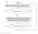
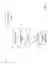

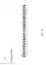

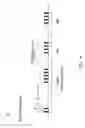


Sources:
- United States Patent and Trademark Office - verify current appl. status at the USPTO↗
Recent applications in this class:
- » 20180242265 2018-08-23
System and method providing optimizations for reduced transmit power control frequency operation - » 20170251440 2017-08-31
Resource control for network devices - » 20160205640 2016-07-14
Almost blank subframe in carrier aggregation - » 20120057623 2012-03-08
Apparatus and method for power control in broadband wireless access system - » 20100103847 2010-04-29
Method and arrangement relating communication devices - » 20100027590 2010-02-04
Modified SIR values for fast power control - » 20070111745 2007-05-17
Power control for high speed packet data transmission - » 20070091853 2007-04-26
Power control for high speed packet data transmission - » 20060099985 2006-05-11
Apparatus and method for radio transmission in a cellular communication system - » 20050143113 2005-06-30
Method for transmitting power control bits and detecting power control rate
Recent applications for this Assignee:
- » 20140328185 2014-11-06
Link layer assisted robust header compression context update management - » 20130315344 2013-11-28
RF transmitter and method of operation - » 20120256863 2012-10-11
Methods for associating objects on a touch screen using input gestures - » 20120252230 2012-10-04
Method and apparatus for coupling portable communication devices - » 20120231737 2012-09-13
ENERGY DISTRIBUTION AMONG ANTENNAS IN AN ANTENNA SYSTEM - » 20120174021 2012-07-05
SYSTEMS AND METHODS FOR DISPLAYING ANDROID APPLICATIONS LAUNCHERS IN WEBTOP APPLICATION TRAY - » 20120173706 2012-07-05
Method and apparatus for managing common and application specific presence information - » 20120172083 2012-07-05
Methods for coordinating wireless coverage between different wireless networks for members of a communication group - » 20120170743 2012-07-05
Methods for establishing a secure point-to-point call on a trunked network - » 20120170502 2012-07-05
Methods for binding and unbinding a MBMS bearer to a communication group in a 3GPP compliant system