Exercise device and method
US20060270534A1
2006-11-30
10/537,240
2003-11-26
✅ Patent granted
US 7,628,741 B2
2009-12-08
WO; PCT/AU03/01576; 20031126
WO; WO2004/050192; 20040617
Loan H Thanh | Allana Lewin
2024-10-05
Abstract:
A device for the exercise of the musculature of the upper arm, said device adapted to provide a resistance force to the rotational movement about the elbow of the forearm towards the upper arm and wherein said rotational movement lies between the limits of approximately an angle of 90° at the elbow and that angle between said forearm and said upper arm limited by contact between said forearm and said upper arm.
Inventors:
- Danny Leonard Adcock 1 🇦🇺 Petersham, Australia
- Jennifer Stephanie Adcock 1 🇦🇺 Petersham, Australia
- Danny Leonard Adcock 1 🇦🇺 Petersham, NSW, Australia
- Jennifer Stephanie Adcock 1 🇦🇺 Petersham, NSW, Australia
Interested in similar patents?
Get notified when new applications in this technology area are published.
Classification:
A63B21/00069 » CPC main
Exercising apparatus for developing or strengthening the muscles or joints of the body by working against a counterforce, with or without measuring devices; Mechanical means for varying the resistance Setting or adjusting the resistance level; Compensating for a preload prior to use, e.g. changing length of resistance or adjusting a valve
A63B21/00185 » CPC further
Exercising apparatus for developing or strengthening the muscles or joints of the body by working against a counterforce, with or without measuring devices using resistance provided by the user, e.g. exercising one body part against a resistance provided by another body part
A63B21/023 » CPC further
Exercising apparatus for developing or strengthening the muscles or joints of the body by working against a counterforce, with or without measuring devices using resilient force-resisters Wound springs
A63B21/4017 » CPC further
Exercising apparatus for developing or strengthening the muscles or joints of the body by working against a counterforce, with or without measuring devices; Interfaces with the user related to strength training; Details thereof; Arrangements for attaching the exercising apparatus to the user's body, e.g. belts, shoes or gloves specially adapted therefor to the upper limbs
A63B21/4021 » CPC further
Exercising apparatus for developing or strengthening the muscles or joints of the body by working against a counterforce, with or without measuring devices; Interfaces with the user related to strength training; Details thereof; Arrangements for attaching the exercising apparatus to the user's body, e.g. belts, shoes or gloves specially adapted therefor to the upper limbs to the wrist
A63B23/1281 » CPC further
Exercising apparatus specially adapted for particular parts of the body for limbs, i.e. upper or lower limbs, e.g. simultaneously for upper limbs or related muscles, e.g. chest, upper back or shoulder muscles primarily by articulating the elbow joint
A63B21/0087 » CPC further
Exercising apparatus for developing or strengthening the muscles or joints of the body by working against a counterforce, with or without measuring devices using hydraulic or pneumatic force-resisters using pneumatic force-resisters of the piston-cylinder type
A63B21/05 IPC
Exercising apparatus for developing or strengthening the muscles or joints of the body by working against a counterforce, with or without measuring devices using resilient force-resisters Linearly-compressed elements
A63B21/02 IPC
Exercising apparatus for developing or strengthening the muscles or joints of the body by working against a counterforce, with or without measuring devices using resilient force-resisters
Description
The present invention relates to aids for the development or rehabilitation of the musculature of the upper arm.
BACKGROUNDThe desire to increase the muscle tone and muscular capacity of the body and specific parts of the body have led to the development of a large range of equipment designed to aid in that process. Such equipment includes weights; stretchable spring arrays and highly complex so-called exercise machines.
The development of the muscles of the arm, in particular the biceps, has generally required the use of weights. These are bulky and inconvenient in many situations and do not allow a specifically useful means and method of exercise in which the range of pivotal movement of the forearm relative to the upper arm is restricted to an angle less than 90 degrees.
The present invention seeks to address these disadvantages or at least provide a useful alternative.
BRIEF DESCRIPTION OF INVENTIONAccordingly, in one broad form of the invention, there is provided A device for the exercise of the musculature of the upper arm, said device adapted to provide a resistance force to the rotational movement about the elbow of the forearm towards the upper arm and wherein said rotational movement lies between the limits of approximately an angle of 90° at the elbow and that angle between said forearm and said upper arm limited by contact between said forearm and said upper arm.
Preferably, said device comprises telescopically assembled inner and outer tubular elements, said tubular elements provided with end closure means at the outward ends of said tubular elements; said outer tubular element provided with an inwardly projecting collar at its inward open end; said inner tubular element provided with an outwardly projecting collar at its inward open end; said collars adapted to prevent the withdrawal of said inner tubular element from said outer tubular element when said tubular elements are telescopically assembled.
Preferably, a compression spring provides an extending force when installed within said telescopically assembled inner and outer tubular members, the ends of said spring acting against said closure means, said extending force urging said tubular elements into a maximum extended position, said extended position limited by contact between said collars.
Preferably, said end closure means of said outer tubular member comprises an end cap, said and cap including a threaded sleeve section adapted to mate with a threaded portion at the outward end of said tubular element; said end cap adapted to allow for the insertion into said tubular members of compression springs of varying spring rates.
In a particular for a Velcro strap or equivalent releaseably connected device can be utilized to attach the device to the wrist of a user.
Preferably, said varying spring rates are in the ranges of 11 to 15 lb and 17 to 21 lb per inch of compression.
Preferably, said end closure means of said inner tubular member is provided with a threaded sleeve portion adapted to mate with an external thread on the outside of said inner tubular member; said threaded sleeve adapted to provide adjustment means to vary the length between said end closure means.
Preferably, said end closure means of said inner tubular member includes a threaded socket; said socket adapted for the attachment of a support pad adapted to fit against the shoulder of a user; said support pad provided with a resilient surface covering.
Preferably, said socket is adapted for the attachment of resilient pad; said resilient pad adapted to fit into the hand of a user.
Accordingly, in a further broad form of the invention there is provided, a device for the exercise of the musculature of the upper arm, said device adapted to provide a resistance force to the rotational movement about the elbow of the forearm towards the upper arm and wherein said rotational movement lies between the limits of approximately an angle of 90° at the elbow and that angle between said forearm and said upper arm limited by contact between said forearm and said upper arm.
Preferably, said device comprises telescopically assembled inner and outer tubular elements, said tubular elements provided with end closure means at the outward ends of said tubular elements; said outer tubular element provided with an inwardly projecting collar at its inward open end; said inner tubular element provided with an outwardly projecting collar at its inward open end; said collars adapted to prevent the separation of said inner tubular element from said outer tubular element when said tubular elements are telescopically assembled.
Preferably, said end closure means at the outward end of said outer tubular element is provided with a piston rod extending from said end closure means substantially the length of said outer tubular member, said piston rod ending in a piston adapted for sliding sealing movement in said inner tubular member.
Preferably, said end closure means of said outer tubular member is in the form of a cap; said cap including a threaded sleeve; said sleeve mating with a threaded outward end portion of said outer tubular member; said sleeve adapted to provide adjustment of the length between said end closure means when said tubular members are in a fully extended position.
Preferably, a compression spring is installed between said cap and the inwardly projecting collar of said inner tubular member; said spring providing an outward urging force biased to return said tubular members to a fully extended position.
Preferably, said inner tubular member is provide with an air flow control valve positioned at said outward end of said inner tubular member.
Preferably, said air control valve is adapted to variably restrict the rate of air flow from said inner tubular member when said piston is driven towards said outward end of said tubular member.
Preferably, said end closure means are provided with resilient pads.
Preferably, one of said end closure means is provided with strapping means adapted to secure the device to the wrist of a user.
Preferably, the overall length of said device when said outer and said inner tubular members are in a fully extended position is in the range of 130 to 180 mm.
Accordingly, in yet a further broad form of the invention, there is provided a device for the exercise of the musculature of the upper arm, said device adapted to provide a resistance force to the rotational movement about the elbow of the forearm towards the upper arm and wherein said rotational movement lies between the limits of approximately an angle of 90° at the elbow and that angle between said forearm and said upper arm limited by contact between said forearm and said upper arm.
Preferably, said device comprises a tubular member containing a compression spring, said expression spring acting on a piston and piston rod coaxial with said tubular member so as to urge said piston and said piston rod into a maximum extended position.
Preferably, the installed length of said compression spring is adjustable so as to vary the compressive force exerted by said spring on said piston and said piston rod; said installed length defined as the length of said spring when said piston and said piston rod are in said maximum extended position.
Preferably, said tubular member is provided with a shoulder yoke, said yoke adapted to support said device at the shoulder of a user; and wherein said piston rod is provided at its outer end with a wrist yoke, said yoke adapted to support said device at the wrist of said user.
Preferably, said shoulder yoke is provided with adjustment means adapted to vary the distance between said shoulder yoke and said wrist yoke.
Preferably, said wrist yoke is provided with strapping means adapted to secure said yoke to the wrist of a user.
Preferably, said rotational movement is approximately restricted between a first angle α and a second angle equal to or less than α/2.
Accordingly, in yet a further broad form of the invention, there is provided a method for the exercise of the musculature of the upper arm, said method including the steps of;
-
- (a) the use of an exercise device providing a resistance force to the rotational movement of the forearm towards the upper arm, said resistance force acting along the line between the shoulder and the wrist of a user;
- (b) adjusting said device so that when in a relaxed state said device restricts the angle at the elbow of said user to an angle equal to or less than 90 degrees;
- (c) adjusting said device so that the resistance force is within the capacity of the user to overcome in the rotational movement of the forearm towards the upper arm; said adjustment being effected by means of springs of varying spring rate or by means of varying the installed length of a compression spring;
- (d) repeated reciprocal rotational movements of the forearm towards the upper arm.
Embodiments of the present invention will now be described with reference to the accompanying drawings wherein:
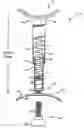
FIG. 1 is partially cut away perspective view of an exercise device according to a first preferred embodiment of the invention.
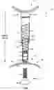
FIG. 2 is a partially cut away perspective view of an exercise device according to a second preferred embodiment of the invention
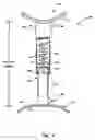
FIG. 3 is a partially cut away side view of an exercise device according to a further preferred embodiment of the invention,
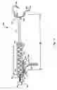
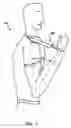
FIG. 4 is a view of the device of FIG. 3 in use
DETAILED DESCRIPTION OF PREFERRED EMBODIMENTSA first preferred embodiment of an exercise device 10 will now be described with reference to FIG. 1 in which an outer tubular member 11 is adapted to telescopically receive an inner tubular member 12. Both outer tubular member 11 and inner tubular masher 12 are closed at their opposite outer ends 13 and 14 respectively, with the closure means of first outer end 13 being in the form of a threaded cap 15 adapted to screw onto a threaded end portion of the tubular member 11. Closure means of the second outer end 14 incorporates a supporting element 16 comprising a curved support 17 and a resilient cover 18 adapted to fit against the shoulder of a user. Supporting element 16 is provided with an internally threaded sleeve (not shown) mating with an external threaded end portion (not shown) of the outer surface of outer tubular member 11, to provide access to replace the spring.
Supporting element 17 is further provided with a threaded socket 25 projecting into inner tubular member 12 which is adapted to receive alternative end unit 19.
Alternative end unit 19 is comprised of a threaded shaft 20 and resilient pad 21. When fitted with alternative end unit 19 device 10 may be operated between the two hands or between the hand and hip of a user, for example.
Outer tubular member 11 is provided with an inwardly projecting retaining collar at its open end 22. Likewise, inner tubular member 12 is provided with an outwardly projecting collar (not shown) at its open end 23, the collars adapted to prevent the separation of inner tubular member 12 from outer tubular member 11 when the device 10 is assembled for use.
A compression spring 24 acts between the outer closed ends 13 and 14 of outer tubular member 11 and inner tubular member 12 respectively, to urge the tubular members into a maximum extended condition. Springs of various spring rates may be installed in the device to provide different levels of effort required to force the telescopic compression of inner tubular member 12 into outer tubular member 11. Preferred spring rates are in the range of 11 to 15 lb and 17 to 21 b per inch of compression.
A preferred arrangement of outer tubular member 11 and inner tubular member 12 allows for a reciprocating telescopic movement of compression and extension of the order of 75 mm. An important feature of the operation of the device is that it should be adjusted to suit a user so that it is the rotational limitation of the user's arm as the forearm contacts the bicep rather than the limit of travel of the telescoping elements of the device which defines the limit of compression stroke when the device is in use. When fully extended and placed between the wrist and the shoulder the adjusted length of the device should define an angle at the elbow of approximately 90°.
In a second preferred embodiment of the invention, an exercise device 100 has again telescopically associated outer tubular member 101 and inner tubular member 102 closed at their outer ends by closure means 103 and 104 respectively.
Outer tubular member 101 is provided with an inwardly projecting retaining collar at its open end 105. Likewise, inner tubular member 102 is provided with an outwardly projecting collar at its end 106, the collars adapted to prevent the separation of inner tubular member 102 from outer tubular member 101 when device 100 is ass assembled for use.
The closure means 103 of outer tubular member 101 is in the form of a screw-on cap 107 which in turn is connected to a piston rod 108 ending in piston 109. Screw-on cap 107 is formed with an extended threaded sleeve section to allow for a range of adjustment in the position of cap 107 at the outer end 103 of outer tubular member 101. When the cap 107 is at a first engaged position, that is at its outermost location on outer tubular member 101, and inner and outer tubular members 101 and 102 are at their maximum extension as allowed by their respective collars, piston 109 is just located within the end 111 of inner tubular member 102.
A compression spring 112 is adapted to act between cap 107 of the outer tubular member 101 and the outwardly projecting collar of the inner tubular member 102 so as to urge the tubular members 101 and 102 into a maximum extended position. In this embodiment the force exerted by spring 112 is only sufficient to return the tubular members to that maximum extended-position.
Piston 109 is adapted to slide within inner tubular member 102 and is provided with sealing means to allow for the compression of the air column between the piston 109 and the closed ouster end 104 of inner tubular member 102. Inner tubular member 102 is provided at its outer end 104 with flow restriction valve 114. Valve 114 is pro vided with control means whereby the rat of flow of air through the valve may be varied, thereby varying the amount of force required to drive piston 109 towards the end 104 of inner tubular member 102. The open end 105 of outer tubular member 101 may be provided with a slot (not shown) so as to accommodate flow restriction valve 114 when the device is driven to maximum compression.
The outer end 113 of inner tubular member 102 and the cap 107 of outer tubular member 101 are provided with resilient pads 115. Optionally, cap 107 may be provided with a strap adapted to pass around the wrist of a user. As a further option, the device may be supplied with an interchangeable end pad in the form of a curved pad adapted to fit against the shoulder of a user.
In yet a further embodiment of an exercise device according to the invention, there is provided with reference to FIG. 4 an exercise device 200 comprising a piston 220 and piston rod 221 telescopically sliding in tubular member 222. Located inside tubular member 222 between at first end 223 of tubular member 222 an the piston 220 is a compression spring 224 so disposed as to provide an outwardly urging force to the piston 220 and piston rod 221.
In a preferred different as shown in FIG. 2, first end 223 of tubular member 222 is provided with spring compression adjustment means 225 so as to vary the urging force of spring 224 on piston 220 and piston rod 221. Spring compression adjustment means 225 comprises an adjustment knob 226, threaded shaft 227 and adjustment piston 228. Rotation of adjustment knob 226 causes axial displacement of adjustment piston 228 as threaded shaft 227 rotates in threaded bush 229 fixed in first tubular member end 223, thereby modifying the installed length ‘L’ of compression spring 224 and the compression force required to urge piston rod 221 and piston 220 inwardly.
Attached towards first end 223 of tubular member 222 is shoulder yoke 230 adapted to fit against the shoulder of a user 231 as shown in FIG. 2. Similarly, at outer end 232 of piston rod 221 is wrist yoke 233. Both shoulder yoke 230 and wrist yoke 233 are provided with resilient pads 234 for the comfort of the user 231. In a preferred embodiment wrist yoke 233 is provided with securing strap 235 adapted to loop around the wrist of user 231. Preferably securing strap 235 is provided with self securing surface means such as Velcrose strips so as to provide convenient variable adjustment of the strap around the wrist of a user.
In a further preferred embodiment the device is provided with adjustment means 236 so that the position of shoulder yoke 230 is adjustable between a first position adjacent to first end 223 of tubular member 222 and selectable positions 237 along a portion of the length of the tubular member. This enables the overall length ‘OL’ between the shoulder yoke and the wrist yoke to be varied to suit the preference and the size of a particular user and adapt the device to its intended range of movement, that is the pivotal movement of the forearm relative to the upper arm through an acute angle. By way of example, the adjustment means may consist of a length of adjusting rail 238 attached to the underside of tabular member 222, the rail provided with a series of discreet holes 239 allowing the shoulder yoke to be secured at any selected hole position, for example by a detent pin.
In use, the device is adjusted so as to define a distance ‘L’ between shoulder yoke 230 and wrist yoke 233 to suit a particular user. Distance ‘L’ should be such as to restrict the angle α where α=/<90° at the elbow when the device is in a relaxed state. After adjusting the compression force of compression spring 224 positioning the device between shoulder and wrist, the user rotates the forearm so as to reduce the distance ‘L’ to approximately
Claims
1. A device for the exercise of the musculature of the upper arm, said device adapted to provide a resistance force to the rotational movement about the elbow of the forearm towards the upper arm and wherein said rotational movement lies between the limits of approximately an angle of 90° at the elbow and that angle between said forearm and said upper arm limited by contact between said forearm and said upper arm.
2. The device of claim 1 wherein said device comprises telescopically assembled inner and outer tubular elements, said tubular elements provided with end closure means at the outward ends of said tubular elements; said outer tubular element provided with an inwardly projecting collar at its inward open end; said inner tubular element provided with an outwardly projecting collar at its inward open end; said collars adapted to prevent the withdrawal of said inner tubular element from said outer tubular element when said tubular elements are telescopically assembled.
3. The device of claim 2 wherein a compression spring provides an extending force when installed within said telescopically assembled inner and outer tubular members, the ends of said spring acting against said closure means, said extending force urging said tubular elements into a maximum extended position, said extended position limited by contact between said collars.
4. The device of claim 3 wherein said end closure means of said outer tubular member comprises an end cap; said end cap including a threaded sleeve section adapted to mate with a threaded portion at the outward end of said tubular element; said end cap adapted to allow for the insertion into said tubular members of compression springs of varying spring rates.
5. The device of claim 4 wherein said varying spring rates are in the ranges of 11 to 15 lb and 17 to 21 lb per inch of compression.
6. The device of claim 5 wherein said end closure means of said inner tubular member is provided with a threaded sleeve portion adapted to mate with an external thread on the outside of said inner tubular member; said threaded sleeve adapted to provide adjustment means to vary the length between said end closure means.
7. The device of claim 6 wherein said end closure means of said inner tubular member includes a threaded socket; said socket adapted for the attachment of a support pad adapted to fit against the shoulder of a user; said support pad provided with a resilient surface covering.
8. The device of claim 7 wherein said socket is adapted for the attachment of resilient pad; said resilient pad adapted to fit into the hand of a user.
9. A device for the exercise of the musculature of the upper arm, said device adapted to provide a resistance force to the rotational movement about the elbow of the forearm towards the upper arm and wherein said rotational movement lies between the limits of approximately an angle of 90° at the elbow and that anile between said forearm and said upper arm limited by contact between said forearm and said upper arm.
10. The device of claim 9 wherein said device comprises telescopically assembled inner and outer tubular elements, said tubular elements provided with end closure means at the outward ends of said tubular elements; said outer tubular element provided with an inwardly projecting collar at its inward open end; said inner tubular element provided with an outwardly projecting collar at its inward open end; said collars adapted to prevent the separation of said inner tubular element from said outer tubular element when said tubular elements are telescopically assembled.
11. The device of claim 10 wherein said end closure means at the outward end of said outer tubular element is provided with a piston rod extending from said end closure means substantially the length of said outer tubular member, said piston rod ending in a piston adapted for sliding sealing movement in said inner tubular member.
12. The device of claim 11 wherein said end closure means of said outer tubular member is in the form of a cap; said cap including a threaded sleeve; said sleeve mating with a threaded outward end portion of said outer tubular member; said sleeve adapted to provide adjustment of the length between said end closure means when said tubular members are in a fully extended position.
13. The device of claim 12 wherein a compression spring is installed between said cap and the inwardly projecting collar of said inner tubular member; said spring providing an outward urging force biased to return said tubular members to a fully extended position.
14. The device of claim 13 wherein said inner tubular member is provide with an air flow control valve positioned at said outward end of said inner tubular member.
15. The device of claim 14 wherein said air control valve is adapted to variably restrict the rate of air flow from said inner tubular member when said piston is driven towards said outward end of said tubular member.
16. The device of claim 15 wherein said end closure means are provided with resilient pads.
17. The device of claim 16 wherein one of said end closure means is provided with strapping means adapted to secure the device to the wrist of a user.
18. The device of claim 17 wherein the overall length of said device when said outer and said inner tubular members are in a fully extended position is in the range of 130 to 180 mm.
19. A device for the exercise of the musculature of the upper arm, said device adapted to provide a resistance force to the rotational movement about the elbow of the forearm towards the upper arm and wherein said rotational movement lies between the limits of approximately an angle of 90° at the elbow and that angle between said forearm and said upper arm limited by contact between said forearm and said upper arm.
20. The device of claim 19 wherein said device comprises a tubular member containing a compression spring, said compression spring acting on a piston and piston rod coaxial with said tubular member so as to urge said piston and said piston rod into a maximum extended position.
21. The device of claim 20 wherein the installed length of said compression spring is adjustable so as to vary the compressive force exerted by said spring on said piston and said piston rod; said installed length defined as the length of said spring when said piston and said piston rod are in said maximum extended position.
22. The device of claim 20 wherein said tubular member is provided with a shoulder yoke, said yoke adapted to support said device at the shoulder of a user; and wherein said piston rod is provided at its outer end with a wrist yoke, said yoke adapted to support said device at the wrist of said user.
23. The device of claim 22 wherein said shoulder yoke is provided with adjustment means adapted to vary the distance between said shoulder yoke and said wrist yoke.
24. The device of claim 22 wherein said wrist yoke is provided with strapping means adapted to secure said yoke to the wrist of a user.
25. The device of any of claims 19 to 24 wherein said rotational movement is approximately restricted between a first angle α and a second angle equal to or less than α/2.
26. A method for the exercise of the musculature of the upper arm, said method including the steps of;
(e) the use of an exercise device providing a resistance force to the rotational movement of the forearm towards the upper arm, said resistance force acting along the line between the shoulder and the wrist of a user;
(f) adjusting said device so that when in a relaxed state said device restricts the angle at the elbow of said user to an angle equal to or less than 90 degrees;
(g) adjusting said device so that the resistance force is within the capacity of the user to overcome in the rotational movement of the forearm towards the upper arm; said adjustment being effected by means of springs of varying spring rate or by means of varying the installed length of a compression spring;
(h) repeated reciprocal rotational movements of the forearm towards the upper arm.
Images & Drawings included:
Sources:
- United States Patent and Trademark Office - verify current appl. status at the USPTO↗
Similar patent applications:
- » 20050003931
Exercise device, method of fabricating exercise device, and method and system for interaction with an exercise device - » 20170007884
Exercise device and method of exercising using said device - » 20170136278
Exercise device and method of exercising using said device - » 20150081245
Exercise support device, control method for exercise support device, and computer-readable storage medium - » 20130337983
SUSPENDED TRAINING EXERCISE DEVICE, METHOD AND KIT - » 20080132391
Dual cam exercise device method and apparatus - » 20070087921
Treatment table and exercise device method and apparatus - » 20110287913
Exercise device, method of use, and method of treating an individual - » 10317899
Wrist, hand and finger exercise device method of use and method of manufacture - » 20240382799
METHOD, EXERCISE DEVICE AND SOFTWARE FOR MEASURING MAXIMUM MUSCLE STRENGTH VALUE
Recent applications in this class:
- » 20250288844 2025-09-18
EXERCISE DEVICE - » 20250288843 2025-09-18
EXERCISE DEVICE CABLE SAFETY LOCKING MECHANISM - » 20250269218 2025-08-28
EXERCISE METHOD AND DEVICE FOR ADJUSTING AN ELASTIC RESISTANCE STRENGTH OF AN ELASTIC BODY THAT IS USED IN EXERCISE OR REHABILITATION. - » 20250195933 2025-06-19
Exercise Machine Resistance Selection System - » 20250177797 2025-06-05
MUSCLE EXERCISE DEVICE - » 20250161733 2025-05-22
SPACER FOR RESISTANCE ADJUSTMENT IN RESISTANCE TRAINING APPARATUS - » 20250144462 2025-05-08
COMPACT EXERCISE APPARATUS - » 20250073519 2025-03-06
EXERCISE EQUIPMENT WITH DYNAMICALLY-ADJUSTABLE RESISTANCE - » 20250025732 2025-01-23
Crossbar Functional Trainer - » 20250010118 2025-01-09
WEARABLE DEVICE FOR PROVIDING EXERCISE MODE BASED ON DISEASE OF USER AND OPERATING METHOD THEREOF