Retention latch for packaging apparatus
US20060283773A1
2006-12-21
11/411,075
2006-04-25
Abstract:
A method and apparatus for handling sensitive components includes a tray having an array of integral latches. A portion of each latch serves to maintain the components on their respective mounts. The method of using the tray involves displacing the latch with an end effector to enable automated removal of the component from the tray.
Inventors:
- David M. Christensen 5 🇺🇸 Fallbrook, CA, United States
- Thi Q. Ho 3 🇺🇸 Murrieta, CA, United States
Interested in similar patents?
Get notified when new applications in this technology area are published.
Classification:
H01L21/67333 » CPC main
Processes or apparatus adapted for the manufacture or treatment of semiconductor or solid state devices or of parts thereof; Apparatus specially adapted for handling semiconductor or electric solid state devices during manufacture or treatment thereof; Apparatus specially adapted for handling wafers during manufacture or treatment of semiconductor or electric solid state devices or components ; Apparatus not specifically provided for elsewhere using specially adapted carriers or holders; Fixing the workpieces on such carriers or holders Trays for chips
B65D85/00 IPC
Containers, packaging elements or packages, specially adapted for particular articles or materials
B65D1/34 IPC
Containers having bodies formed in one piece, e.g. by casting metallic material, by moulding plastics, by blowing vitreous material, by throwing ceramic material, by moulding pulped fibrous material, by deep-drawing operations performed on sheet material Trays or like shallow containers
Description
RELATED APPLICATIONSThis application claims the benefit of provisional application 60/681,294 filed on May 16, 2005.
BACKGROUND OF THE INVENTIONDuring shipping or handling of a tray loaded with sensitive components, the components undergo vibration that can result in their displacement from their mounts. Such displacement can damage the components or result in errors during automated pick up of the components. In addition, as the components move away from their mounts, the tray is abraded. Repeated abrasion leads to particle generation which contaminates the sensitive components. Consequently, a need exists for a tray that maintains delicate components in their desired position and that protects the components from damage during shipping and handling.
SUMMARY OF THE INVENTIONThe invention concerns an apparatus for handling delicate components or workpieces such as electronic components. The apparatus may be used during processing, cleaning or transport of the workpieces.
A first embodiment of the invention is an apparatus for handling workpieces comprising a tray on which an array of mounts and an array of latches are attached. The latches are integrally formed with the tray. A portion of each latch is spaced apart from a portion of each workpiece. Each latch has a hook that maintains each workpiece on its respective mount.
The invention also concerns a method for using the tray with an end effector during an automated assembly process. The end effector both releases the latch and removes the workpieces from the tray.
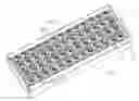
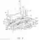
BRIEF DESCRIPTION OF THE DRAWINGSFIG. 1 is a perspective view of a preferred embodiment of the tray of the present invention.
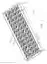
FIG. 2 is an exploded view of a portion of FIG. 1 containing a workpiece therein.
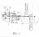
FIG. 3 is a section view of one of the latches in FIG. 2.
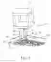
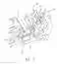
FIG. 4 is a perspective view of an end effector suitable for use with the tray of FIG. 1.
FIG. 5 is an exploded view of the cam portion of the end effector of the present invention.
FIG. 6 is an enlarged view of the end effector being used to grasp different portions of a component from a tray.
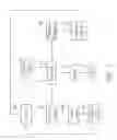
FIG. 7 is a schematic drawing of the tool interface attached to the end effector of FIG. 4.
DETAILED DESCRIPTION OF THE INVENTIONThe invention will now be described in detail with reference to FIGS. 1 and 2. FIG. 1 illustrates a tray 100 having an array of mounts 30 upon which a component or part of a component is placed. FIG. 1 also shows optional chamfered ribs 70 on the rectangular perimeter 75 of tray 100. On the walls opposite perimeter 75 are recesses (not shown) that receive ribs 70 from a second tray to facilitate stacking. A third tray is able to stack onto tray 100 by mating its recesses to ribs 70 on tray 100. Ribs 70 facilitate separating a stack of trays. As without ribs 70, the trays of the invention tend to stick together making disassembly of the stack difficult.
Tray 100 has a major surface 15 upon which an array of latches 50 is integrally formed. Latches 50 are more clearly shown in FIG. 2. Whenever workpiece 65 moves relative to its mount, a portion of latch 50 maintains workpiece 65 in its proper position during assembly, shipping, and handling. Both the mounts 30 and latches 50 are perpendicular to the floor 23 of tray 100. Mounts 30 may have more than one type of shape within the same tray. In FIG. 2, for example, certain mounts 30 have a circular shape, while others have a substantially rectangular shape.
FIG. 2 also illustrates standoffs 27A, 27B attached to major surface 15. Standoffs 27A, 27B further secure workpiece 65 during shipping and handling of the trays. In particular standoffs 27A, 27B and mounts 30 and 31 restrict x/y movement of the workpiece. In the embodiment shown, standoffs 27A, 27B flank an inner periphery of a workpiece as shown in FIG. 2.
Workpieces are manually placed upon one or more mounts 30 of tray 100 by an operator. FIG. 2 illustrates a voice coil 65 on one mount and a flexible circuit board 68 on another mount. In this embodiment, latch 50 is above one side of voice coil 65. Although specific disk drive components are shown in tray 100, other types of workpieces may also be handled by the trays of this invention. For example, tray 100 can also store read/write heads, head suspensions, micro-actuators, as well as the head gimbal assembly shown in FIG. 2.
On the free end of latch 50 is a hook 52 that slides over one side of workpiece 65. Hook 52 is separated from workpiece 65 by a narrow space of approximately 0.002 inches. Hook 52 preferably runs parallel to the parting line of tray 100. Each latch is preferably above a side of a different workpiece. Latch hook 52 prevents workpiece 65 from tilting or displacement during shipping or handling. Latch 50 thereby ensures that the workpieces remain on their mounts within an area surrounding the workpiece called the “retention space”. For example, if workpiece 65 vibrates, hook 52 on latch 50 blocks to workpiece 65 from falling off its mount, thereby retaining workpiece 65 in its desired position on the mount. By providing a latch 50 and retention space, workpiece 65 is prevented from abrading tray 100. In turn, the limited movement of the workpiece relative to its mount results in less contamination, since particle generation is virtually avoided by the reduction in tray abrasion. Any residue that may be generated can be removed through the plurality of openings 37 that penetrate floor 23.
Latch 50 can be a clip, spring, or any other similar type of resilient mechanism. A sectional view of a preferred embodiment of latch 50 is provided in FIG. 3. As shown in FIG. 3, latch 50 consists of a first loop 51 and a second loop 53. The center-to-center distance between loop 51 and loop 53 has a distance 310 of approximately 3.80 mm. The free end of loop 51 has a hook 52 that runs parallel to the parting line of tray 100. In a preferred embodiment, the bottom portion 55 of hook 52 is separated by a distance 320 of approximately 3.70 mm from reference plane 35. The two loops 51, 53 have external radii of 1.60 mm and 1.80 mm, respectively. The thickness of the latches preferably ranges from approximately 0.60 mm to 1.20 mm. Latches having the above dimensions are effective in restraining excessive vertical movement of a workpiece.
Latch 50 is generally stationary during use. However, as explained below, latch 50 can be displaced prior to removing components from tray 100. In this case, latch 50 has a draft angle that ranges from 0.50 to 2.0 degrees, and a spring constant of between 4.0 and 5.0 lbs/inch. In a preferred embodiment latch 50 has a spring constant of approximately 4.20 lbs/inch.
Workpieces are preferably removed from tray 100 using a robotic system. One such system, illustrated in FIG. 4, employs an end effector 40 comprising gripping arms 44, 46 and a cam 73. As shown in FIG. 4, cam 73 is parallel to both gripping arms 44, 46. End effector 40 operates to sequentially transfer each component from tray 100. FIG. 4 also illustrates a tool mounting station 75 upon which various tools for operating the end effector are attached.
The manner in which the latch is cleared from the retention space will now be described. FIG. 5 illustrates an enlarged view of cam 73. Cam 73 includes a shaft 48 and a lobe 43 that are coupled to a motor (not shown). Both the shaft 48 and lobe 43 rotate to displace hook 52 away from component 65. Lobe 43 gradually displaces hook 52 away from the retention space. Cam 73 maintains latch 50 in an extended position until the components 65 and 68 have been lifted away from tray 100.
When latch 50 is outside the retention space, gripping arms 44 and 46 are simultaneously lowered to the position shown in FIG. 6—just above components 65 and 68. Both of the gripping arms 44, 46 operate in unison to retrieve components from tray 100. Specifically, while gripping arm 44 grasps component 65, gripping arm 46 captures HSA 68. Gripping arm 46 may comprise a pneumatic cylinder that operates with air pressure sufficient to lift up parts being stored in tray 100. In the present embodiment, pneumatic cylinder 46 picks up a head stack assembly (HSA) 68 using between about 5-10 psi of air pressure.
Gripping arm 46 includes locating pins 41 within a groove on the underside of cylinder 46. Locating pins 41 move outward along the groove (not shown) to grasp HSA 68 via the workpiece openings 33. The pneumatic air pressure exiting cylinder 46 enables the cylinder 46 to effectively retain HSA. The other gripping arm 44 is coupled to a vacuum source as indicated in the schematic of FIG. 7. FIG. 6 illustrates gripping arm 44 as including a tubular stem 38 and a cup 31 that suctions component 65 with a vacuum. While cylinder 46 grips HSA 68, gripping arm 44 grips component 65. When a sensor detects that both 65 and 68 are adequately grasped, end effector 40 moves components 65 and 68 out of their mounts 30 and into hardware, such as a disk drive, printed circuit board or computer shell. Once components 65 and 68 are lifted above the retention space, cam 73 returns latch 50 to a nonextended position. Then end effector 40 transfers the workpieces into a disk drive, or other hardware. Subsequently, end effector 40 is indexed by a controller to return to a new position on tray 100.
An example of a suitable tool interface for end effector 40 is shown in FIG. 7. A robotic controller 82 is coupled to a vacuum source, a motor, and a pressure regulator. Pressure regulator 63 ensures that the pressure exiting cylinder 46 is within the desired ranged necessary to grip the components stored within tray 100. Vacuum is supplied through a control valve and a vacuum stem 38. Signals from both gripping arm 44 and pneumatic cylinder 46 are fed to controller 82 by the sensor. The end effector 40 may optionally be coupled to a machine vision system provided by, for example, video cameras connected to a computer processor, so that the robot 82 can recognize the location of the end effector and adjust its position. The controller thus controls the indexing and movement of end effector 40 during automated retrieval of components from tray 100.
The trays of the present invention are preferably manufactured with a standard injection molding process. Suitable molding materials for forming the tray include conductive, thermoplastic, non-conductive, and insulated plastic. In addition, the trays can be manufactured from material having electrostatic dissipating properties. The trays may also be manufactured using a thermoformed process.
While the present invention has been described with specific examples, the skilled artisan will appreciate that various features of the invention may be modified without departing from the spirit and scope of the invention. It is therefore the intent that the scope of the invention is to be defined by the appended claims.
Claims
What is claimed:1. An apparatus for handling workpieces comprising:
a tray having a major surface;
an array of mounts attached to the major surface upon which at least one workpiece is placed;
an array of latches integrally formed with the tray, wherein each latch is separated from the workpiece by a narrow space.
2. The apparatus of claim 1, wherein the array of mounts are adjacent to the array of latches.
3. The apparatus of claim 1, wherein a hook on one end of each latch is above a retention space adjacent said workpiece.
4. The apparatus of claim 1, wherein the latch comprises a resilient spring in which a portion of the spring is below the plane of the major surface.
5. The apparatus of claim 3, wherein the hook restrains excessive movement of a workpiece positioned below the latch.
6. The apparatus of claim 1, wherein the latch is orthogonal to the major surface of the tray.
7. The apparatus of clam 1, further comprising a plurality of standoffs on the major surface.
8. The apparatus of claim 1, wherein the workpiece comprises a read/write head, head suspension, micro-actuator, or head gimbal assembly.
9. An apparatus for handling a plurality of workpieces comprising:
a tray having two endwalls and two sidewalls and a major surface adapted to support the workpiece;
an array of mounts attached to the major surface wherein each mount receives a workpiece;
an array of resilient members attached to the major surface and separate from the array of mounts, at least one resilient member being above one of the plurality of workpieces; wherein each resilient member maintains each workpiece on its respective mount.
10. The apparatus of claim 9, wherein part of the resilient member is below the plane of the major surface.
11. The apparatus of claim 9, wherein each resilient member has a hook on one end above a retention space adjacent said workpiece.
12. The apparatus of claim 9, wherein the resilient member comprises a latch, spring, clip, or similar mechanism.
13. The apparatus of claim 9, wherein the resilient member restrains excessive vertical movement of the workpiece.
14. The apparatus of claim 9, wherein the sidewalls of the tray are provided with a chamfered rib for stacking purposes.
15. The apparatus of claim 9, wherein the workpiece comprises a read/write head, head suspension, micro-actuator, or head gimbal assembly.
16. A method of using an apparatus for handling a workpiece comprising a unitary structure that includes:
a) providing a tray having an array of latches and an array of mounts on a major surface;
b) inserting a workpiece on one of the array of mounts beneath a latch that is integral with the tray;
c) robotically displacing the latch into an extended position; and
d) then removing the workpiece from the tray.
Images & Drawings included:

Sources:
- United States Patent and Trademark Office - verify current appl. status at the USPTO↗
Recent applications in this class:
- » 20240404856 2024-12-05
MODULE TRAY FOR SEMICONDUCTOR DEVICE - » 20240404855 2024-12-05
MODULE TRAY FOR SEMICONDUCTOR DEVICE - » 20240355657 2024-10-24
HOLDING PLATE, HOLDING SYSTEM, USE OF THE HOLDING PLATE, USE OF THE HOLDING SYSTEM AND PROVISIONING METHOD - » 20240312815 2024-09-19
FACEPLATE LOADING PLATFORM - » 20240170315 2024-05-23
CLIP AND LID SYSTEM FOR A CHIP TRAY - » 20240055286 2024-02-15
Module tray for semiconductor device - » 20240047249 2024-02-08
Transfer system for wafer cassettes - » 20230253226 2023-08-10
CHIP CARRIER - » 20230170236 2023-06-01
TRAY CARRIER AND CORRESPONDING METHOD - » 20230101674 2023-03-30
TRAY AND DESTRUCTIVE ANALYSIS AUTOMATION APPARATUS INCLUDING THE SAME