Fuel filler cap
US20060283860A1
2006-12-21
11/452,975
2006-06-15
Abstract:
A fuel filler cap has a filler cap main body, which is configured to be screwed into a fuel inlet and generates a click sound when it properly closes the fuel inlet, and an illustration portion provided in the filler cap main body and including an illustration portion that leads in a closing operation with the click sound.
Interested in similar patents?
Get notified when new applications in this technology area are published.
Classification:
B60K15/0406 » CPC main
Arrangement in connection with fuel supply of combustion engines or other fuel consuming energy converters, e.g. fuel cells ; Mounting or construction of fuel tanks; Fuel tanks; Tank inlets Filler caps for fuel tanks
B60W2050/143 » CPC further
Details of control systems for road vehicle drive control not related to the control of a particular sub-unit, e.g. process diagnostic or vehicle driver interfaces; Interaction between the driver and the control system; Means for informing the driver, warning the driver or prompting a driver intervention Alarm means
B65D41/04 IPC
Caps, e.g. crown caps or crown seals, i.e. members having parts arranged for engagement with the external periphery of a neck or wall defining a pouring opening or discharge aperture; Protective cap-like covers for closure members, e.g. decorative covers of metal foil or paper; Caps or cap-like covers without lines of weakness, tearing strips, tags, or like opening or removal devices Threaded or like caps or cap-like covers secured by rotation
B65D47/02 IPC
Closures with filling and discharging, or with discharging, devices for initially filling and for preventing subsequent refilling
Description
CROSS-REFERENCE TO RELATED APPLICATIONSThis non-provisional application incorporates by reference the subject matter of Application No. 2005-176571 filed in Japan on Jun. 16, 2005, on which a priority claim is based under 35 U.S.C. §119(a).
BACKGROUND OF THE INVENTION1. Field of the Invention
The present invention relates to a fuel filler cap, which closes a fuel inlet of, for example, a car.
2. Description of the Related Art
Generally, a fuel inlet of a car is closed by a fuel filler cap, which is screwed after fueling, as disclosed in, for example, Jpn. Pat. Appln. KOKAI Publication No. 11-254979.
To prevent fuel from leaking from the fuel inlet, the fuel inlet need be closed by a fuel filler cap securely.
To securely close the fuel inlet, a technique provides a fuel filler cap incorporating a click generating portion. In this art, when the fuel filler cap is screwed in by a predetermined amount, an operation handle portion in the click generating portion rotates at idle and a click sound is generated. With this structure, the operator is led to close the fuel filler cap securely until fastening force exceeding predetermined force is generated. As a result, fuel leakage can be prevented.
Some types of fuel filler cap body have a letter portion, which indicates letters to lead the operator to continue the closing operation until a predetermined fastening torque is generated.
In this type of fuel filler cap, however, since the space for indicating letters is limited, letters may inevitably be small. Therefore, even if the fuel filler cap bears the letters instructing the operator to fasten the cap by fastening torque of a predetermined level or higher, if a car user (operator) having little knowledge of cars is refilling the car in a self-service gas station or the like, it is difficult for the operator to recognize the contents of the indication of the closing operation within a short period of time. Under these circumstances, there is a demand for a technique to assist the operator to recognize the instructions within a short period of time in which he or she is closing the fuel filer cap after fueling, and lead the operator to fasten the cap with fastening torque of a predetermined level or higher.
BRIEF SUMMARY OF THE INVENTIONAn object of the present invention is to provide a fuel filler cap which leads the operator to fasten the cap with fastening torque of a predetermined level or higher.
To achieve the above object, according to an aspect of the present invention, the filler cap body includes an illustration portion to lead the operator to perform a closing operation with a click sound.
BRIEF DESCRIPTION OF THE SEVERAL VIEWS OF THE DRAWINGThe nature of this invention, as well as other objects and advantages thereof, will be explained in the following with reference to the accompanying drawings, in which like reference characters designate the same or similar parts throughout the figures and wherein:
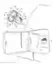
FIG. 1 is a perspective view showing a fuel filler cap according a first embodiment of the present invention and a fuel inlet on which the cap is to be attached;
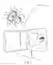
FIG. 2 is an enlarged front view of an illustration portion designated by A in FIG. 1;
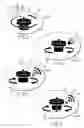
FIG. 3 is a front view showing an illustration portion according to a second embodiment of the present invention;
FIG. 4 is a front view showing an illustration portion according to a third embodiment of the present invention; and
FIG. 5 is a front view showing an illustration portion according to a fourth embodiment of the present invention.
DETAILED DESCRIPTION OF THE INVENTION First EmbodimentA first embodiment of the present invention will be described with reference to FIGS. 1 and 2.
FIG. 1 shows a part of a rear side of a vehicle, for example, a car. In FIG. 1, a reference numeral 1 denotes a car body. A fuel opening portion 2 is formed in a panel portion forming the rear side of the car body 1. A fuel lid 3 opens and closes the fuel opening portion 2. A fuel filler neck bracket 4 is attached to an interior of the fuel opening portion 2. A fuel inlet 5 is formed in a bottom portion of the bracket 4. The fuel inlet 5 communicates with a fuel tank (not shown) via a fuel filler neck 6 and a filler hose (not shown). The car is refueled through the fuel inlet 5. A female screw portion 7 is formed in the inner surface of an end portion of the fuel filler neck 6 connected to the fuel inlet 5.
A fuel filler cap 10 closes the fuel inlet 5. The cap 10 has a main body 10a as a filler cap main body. The main body 10a has, for example, a screw portion 12 and an operation handle portion 13 for operating the screw portion 12. The screw portion 12 has a short columnar shape, and is configured to be screwed into the fuel inlet 5. An operation handle portion 13, which is disc-shaped, is connected to a proximal portion of the screw portion. A male screw portion 14 is formed on a peripheral surface of the screw portion 12.
The operation handle portion 13 has a disc portion 15 and a holding portion 16. The disc portion 15 has an outer diameter larger than the diameter of the fuel inlet 5. The holding portion 16 projects from a central portion of an outer surface of the disc portion 15. When the operator holds the holding portion 16, inserts a top end portion of the screw portion 12 into the fuel inlet 5, and rotates the screw portion 12 with the holding portion 16, for example, clockwise, the screw portion 12 is screwed into the fuel inlet 5 until the disc portion 15 is brought into contact with an opening edge of the fuel inlet 5.
A click generating portion 20 (click generating function) is formed in a part of the main body 10a, for example, between the screw portion 12 and the operation handle portion 13. The click generating portion 20 supports, for example, the screw portion 12 and the disc portion 15 to be rotatable around an relative to each other.
The click generating portion 20 includes a projection group 21. The projection group 21 is formed in one of the proximal portion of the screw portion 12 and the disc portion 15. In the projection group 21, a plurality of projections are annularly arranged (annular broken lines in FIG. 1 indicate the position of the projection group 21). The click generating portion 20 includes an engaging portion 22 (only a part of which is shown) and an elastic engaging portion 23 (only a part of which is shown). An engaging portion 22 and an elastic engaging portion 23 are formed in the other of the proximal portion of the screw portion 12 and the disc portion 15. The engaging portion 22 engages with the projection group 21 in a direction in which the fuel filler cap 10 is loosened. The elastic engaging portion 23 elastically engages with the projection group 22 in a direction in which the filler cap 10 is closed.
The screw portion 12 and the operation handle portion 13 are rotatably connected to each other at a support portion 24. The elastic engaging portion 23 is set so as to run over the projections when it receives fastening torque of a predetermined level or higher. Therefore, when the fuel filler cap 20 is screwed into the fuel inlet 5 properly, the elastic engaging portion 23 exhibits behavior of running over the projections. As a result, the operation handle portion 13 (the disc portion 15 and the holding portion 16) rotates at idle, thereby relieving excessive fastening torque. In this time, the elastic engaging portion 23 behavior of running over the projection generates a click sound. In other words, the fuel filler cap 20 has such a structure as to generate a click sound while rotating at idle, when it is closed properly.
The main body 10a of the fuel filler cap 10 has an illustration portion 30, which leads the operator to perform a proper closing operation. The illustration portion 30 is located in a position easily visible to the operator, as designated by A in FIG. 1. For example, it is provided on a surface of the operation handle portion 13 which faces the operator; more specifically, a side surface 15a of the disc portion 15 which faces the operator (adjacent to the holding portion 16). FIG. 2 shows the illustration portion 30, which is enlarged. The illustration portion is depicted preferably in white on a black background, because the fuel filler cap 10 is generally black. The illustration portion 30 is depicted with black lines on a white background in FIG. 1. In FIG. 2, since the drawing paper is white, the illustration portion 30 is depicted in black on the white background.
The illustration portion 30 will now be described with reference to FIG. 2. The illustration portion 30 is made up of a main body shape portion 31 representing an exterior form (shape) of the main body (filler cap main body) 10a, an arrow portion 32 representing the state of closing the main body 10a, and a sound generation symbol 33 representing that, for example, a few click sounds are generated from the main body 10a. The main body shape portion 31 corresponds to an example of a first illustration symbol. The arrow portion 32 corresponds to an example of a second illustration symbol. The arrow portion 32 is depicted, for example, clockwise, and expresses a closing direction. The sound generation symbol 33 corresponds to an example of a third illustration symbol. It is depicted as the combination of two wave portions 33a arranged side by side, each consisting of a plurality of arc lines different in length, and two short arrows 33b representing the movement of the operation handle portion 13 when the click sound is generated.
The illustration portion 30 expresses that operation of closing the fuel filler cap 10 which is required for preventing fuel leakage. More specifically, it expresses the operation of “rotating the fuel filler cap 10 clockwise until a click sound is generated a few times”.
With the fuel filler cap 10 constructed as described above, the operator can understand the contents of operation only by looking at the illustration portion 30. For example, when closing the fuel inlet 5 after refueling, the operator understands that it is necessary to insert the fuel filler cap 10 into the fuel inlet 5 and thereafter rotate the cap 10 until a click sound is generated a few times, based on the illustration representing the main body shape portion 31, the arrow portion 32 and the sound generation symbol 33.
In accordance with the instructions, the operator inserts the screw portion 12 of the fuel filler cap 10 into the fuel inlet 5 and then rotates the cap clockwise (at idle) until a click sound is generated a few times as indicated on the illustration portion 30. Thus, a closing operation is performed securely; that is, the fuel filler cap 10 is fastened with fastening torque of a predetermined level or higher, thereby preventing fuel leakage securely. In other words, the fuel filler cap 10 is prevented from being attached loosely to the fuel inlet 5.
Moreover, since the illustration portion 30 is simple and available irrespective of language, it is advantageous in that it can be used in any countries. Especially the illustration portion 30 is easily visible, since it is located in such a position of the operation handle portion that faces the operator. Furthermore, the illustration portion 30 is depicted by using the main body shape portion 31, the arrow portion 32 representing the closing direction and the sound generation symbol 33 representing that, for example, a click sound is generated a few times. Thus, the contents of the closing operation are expressed in such a manner that the operator can easily understand them.
Second EmbodimentFIG. 3 shows a second embodiment of the present invention.
In this embodiment, for example, a propagation symbol 40, representing that sound is propagated from one point, is used as the sound generation symbol 33. The illustration portion 30 made up of the propagation symbol 40, the main body shape portion 31 and the arrow portion 32 also provides the same effect as that in the first embodiment.
Third EmbodimentFIG. 4 shows a third embodiment of the present invention. In this embodiment, for example, a speaker symbol 45, representing that sound is generated from a speaker, is used as the sound generation symbol 33. The illustration portion 30 made up of the speaker symbol 45, the main body shape portion 31 and the arrow portion 32 also provides the same effect as that in the first embodiment.
Fourth EmbodimentFIG. 5 shows a fourth embodiment of the present invention. This embodiment is a modification of the second embodiment. In the fourth embodiment, an arrow portion 41, representing that the main body 10a is inserted in the fuel inlet 5, is added to the second embodiment. The use of the arrow portion 41 makes the operation of closing the fuel filler cap 10 easier to understand.
In the descriptions of the second to fourth embodiments, the same portions as those in the first embodiment are identified by the same reference numerals and the descriptions thereof are omitted.
The present invention is not limited to the above embodiments, but may be variously modified without departing from the scope of the invention. For example, in the above embodiments, the illustration portion 30 is made up of the main body shape portion 31, the arrow portion 32 and the sound generation portion 33, or additionally includes the arrow portion 41. However, another symbol may be used in the illustration portion 30, as far as it makes the closing operation is easily understandable. Further, the illustration portion 30 may be depicted in a different expression, or black and white in the illustration portion 30 may be reversed. Furthermore, the illustration portion 30 may be expressed in line drawing or in any other color or a variety of colors.
The invention thus described, it will be obvious that the same may be varied in many ways. Such variations are not to be regarded as a departure from the spirit and scope of the invention, and all such modifications as would be obvious to one skilled in the art are intended to be included within the scope of the following claims.
Claims
What is claimed is:1. A fuel filler cap comprising:
a filler cap main body, which is configured to be screwed into a fuel inlet and generates a click sound when it properly closes the fuel inlet; and
an illustration portion, which is provided in the filler cap main body and leads in a closing operation with the click sound.
2. The fuel filler cap according to claim 1, wherein the filler cap main body includes an operation handle portion to perform the closing operation, and the illustration portion is provided in a surface of the operation handle that faces in front.
3. The fuel filler cap according to claim 1, wherein the illustration portion includes a first illustration symbol representing a filler cap main body shape, a second illustration symbol representing a direction of closing the filler cap main body and a third illustration symbol representing that the click sound is generated from the filler cap main body.
4. The fuel filler cap according to claim 2, wherein the illustration portion includes a first illustration symbol representing a filler cap main body shape, a second illustration symbol representing a direction of closing the filler cap main body and a third illustration symbol representing that the click sound is generated from the filler cap main body.
Images & Drawings included:
Sources:
- United States Patent and Trademark Office - verify current appl. status at the USPTO↗
Similar patent applications:
- » 20220227222
Fuel filler cap - » 20050263526
Fuel filler cap - » 20060246819
Fuel filler cap for a model vehicle - » 20070144609
Fuel filler cap for a model vehicle - » 20110139780
FUEL FILLER CAP - » 20210016657
FUEL FILLER CAP CANISTER - » 20050263525
Fuel filler cap - » 20080000543
Filler cap of fuel tank - » 20190210455
Filler cap for fuel tank - » 20090272746
Fuel Cap and Filler Neck
Recent applications in this class:
- » 20230347731 2023-11-02
Fuel type identifying gas cap - » 20230339310 2023-10-26
Closing system for vehicle supply system - » 20230173913 2023-06-08
Method and system for determining the closure status of a fuel tank closure - » 20230135107 2023-05-04
Fuel cap for vehicle having locking structure generating sound interval - » 20230128430 2023-04-27
Fuel cap - » 20230087162 2023-03-23
Driving device for energy replenishment port visor member - » 20220402356 2022-12-22
System for controlling vehicle - » 20220227223 2022-07-21
Fully-integrated, fluid flow-control module designed for installation within an ISO filler neck of a top-fill def tank - » 20220227222 2022-07-21
Fuel filler cap - » 20220219527 2022-07-14
Fuel filler pipe