Apparatus and method for installing lines in conduits
US20060284149A1
2006-12-21
11/183,371
2005-07-18
Abstract:
An apparatus for placing lines in a conduit is disclosed. The device uses a battery powered, motor driven wheeled body to roll through the conduit pulling a jet line. The apparatus is used instead of “fish” tape, vacuum, or compressed air to draw a jet line through the conduit.
Interested in similar patents?
Get notified when new applications in this technology area are published.
Classification:
H02G1/08 » CPC main
Methods or apparatus specially adapted for installing, maintaining, repairing or dismantling electric cables or lines for laying cables, e.g. laying apparatus on vehicle through tubing or conduit, e.g. rod or draw wire for pushing or pulling
H02G1/085 » CPC further
Methods or apparatus specially adapted for installing, maintaining, repairing or dismantling electric cables or lines for laying cables, e.g. laying apparatus on vehicle through tubing or conduit, e.g. rod or draw wire for pushing or pulling using portable tools
E21C29/16 » CPC further
Propulsion of machines for slitting or completely freeing the mineral from the seam by cable or chains by haulage cable or chain pulling the machine along the working face Winches or other means for pulling cable or chain
Description
CROSS REFERENCE TO RELATED APPLICATIONSThis application is a continuation-in-part of co-pending and co-owned U.S. patent application Ser. No. 11/154,506, entitled “Apparatus and Method for Installing Lines in Conduits”, filed with the U.S. Patent and Trademark Office on Jun. 16, 2005 by the inventor herein, the specification of which is included herein by reference.
BACKGROUND OF THE INVENTION1. Field of the Invention
This invention generally relates to the field of line threading devices for elongated conduits and, in particular, to an apparatus and method of installing utility lines, such as telephone, fiber optic, or electrical wiring in a conduit.
2. Background of the Prior Art
As most electricians are aware, one of the most difficult chores that they encounter is the threading of wires and cable through elongated tubular conduits. Depending on the gauge and composition of the wires, as well as the length of the conduits and the number and sharpness of the bends in the conduit, feed of the wires through the conduits can be a difficult and trying chore. These difficulties have spurred much activity in terms of time and effort in an attempt to devise a suitable system or apparatus for “fishing” conduit that would be effective, inexpensive, and simple enough to be conducted by unskilled labor working under the direction of a professional electrician.
One approach has involved the use of a “fish tape” which consists of a thin, highly flexible metal strap or tape that can be inserted into one end of the conduit and pushed through and out the other end of the conduit. The wire is then connected to the fish tape at one end of the conduit and the fish tape drawn back through the conduit with the wire attached. Such a system works fairly well, where the length of conduit is short, and the bends in the conduit are kept shallow and few in number. However, this is not always practicable.
Another approach in common use involves introducing a light weight rope, cord, or thread into the conduit by attaching it to a projectile or missile that is then inserted into one end of the conduit and driven through by air or other fluid admitted under pressure into the conduit behind the projectile. Alternatively, a partial vacuum can be created in the conduit ahead of the projectile, causing the projectile to be sucked through the conduit. In each instance, the cord is drawn with the projectile or missile through the conduit, the cord then being useful as a pull line to introduce the wire.
Such projectiles or missiles have taken several forms. For example, it was early proposed that the missile be light in weight and fit loosely within the conduit so that it would not catch as it is driven through the conduit. Such a projectile was usually given the shape of a cone, a cup, or a thimble and arranged so as to present a flared wide area surface to increase its response to the force of the pressurized fluid. However, as the projectile moved away from the source of pressurized air, the inefficiency of the system became more pronounced, and the missile would decelerate and often come to a halt short of the conduit end. The employment of such a loosely fitting missile was particularly unsatisfactory where it was proposed to move the projectile in response to creation of a vacuum in the conduit ahead of the missile.
Although each of the projectiles worked satisfactorily under controlled circumstances, each presented its own special problems. In many instances, the conduit may be in the ceiling requiring the high pressure or vacuum hose to be lifted over the operator's head throughout the duration of the procedure. Often, the project would get stuck in the conduit. Particularly in the case of very long conduits, the pressure or vacuum system tends to be less effective.
Accordingly, there remains a need for a safe and simple apparatus that is effective in threading a line into a conduit to install telephone, electric, or fiber optic lines.
SUMMARY OF THE INVENTIONIt is, therefore, an object of the present invention to provide a device for installing lines in conduits that avoids the disadvantages of the prior art.
It is another object of the present invention to provide a motorized conduit “mouse” that rolls through the conduit. A related object is to provide a conduit “mouse” having a motor and at least one drive wheel. A further related object is to provide a conduit “mouse” that can pull a jet line through a conduit.
Another object of the present invention is to provide a device for installing lines in conduits that is effective in elongated conduits up to several hundred feet long. A related object of the present invention is to provide a device for installing lines in conduits that is effective in conduits of varying diameters.
In accordance with the above objects, a device for installing lines in conduits is disclosed. The device uses a battery powered, motor driven wheeled body to roll through the conduit pulling a jet line. The apparatus is used instead of “fish” tape, vacuum, or compressed air to draw a jet line through the conduit.
BRIEF DESCRIPTION OF THE DRAWINGSThe above and other features, aspects, and advantages of the present invention are considered in more detail, in relation to the following description of embodiments thereof shown in the accompanying drawings, in which:
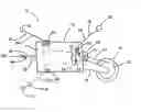
FIG. 1 shows a side elevational view of a line installing apparatus according to one embodiment of the present invention.
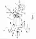
FIG. 2 shows a plan view of a line installing apparatus according to one embodiment of the present invention.
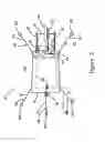
FIG. 3 shows an end elevational view of a line installing apparatus according to one embodiment of the present invention.
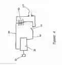
FIG. 4 shows an electrical schematic diagram for a line installing apparatus according to one embodiment of the present invention.
DETAILED DESCRIPTION OF THE INVENTIONThe invention summarized above and defined by the enumerated claims may be better understood by referring to the following description, which should be read in conjunction with the accompanying drawings in which like reference numbers are used for like parts. This description of an embodiment, set out below to enable one to practice an implementation of the invention, is not intended to limit the preferred embodiment, but to serve as a particular example thereof. Those skilled in the art should appreciate that they may readily use the conception and specific embodiments disclosed as a basis for modifying or designing other methods and systems for carrying out the same purposes of the present invention. Those skilled in the art should also realize that such equivalent assemblies do not depart from the spirit and scope of the invention in its broadest form.
Referring to the figures, FIGS. 1, 2, and 3 show a conduit “mouse”, indicated generally as 10, according to the present invention. The “mouse” 10 comprises a substantially cylindrical body 13 that is generally hollow and open on a front end and closed by a plate 14 on a back end. A pair of arms 15, 16 extends from the front end of such body 13. The arms 15, 16 support at least one drive wheel 19 that rotates about an axle 22. In a preferred embodiment, an electric motor 25 that is powered by a battery 28 is operationally connected to the at least one wheel 19 by a pulley 31. The pulley 31 is driven by a drive flange 33 on the operational output of the motor 25. The pulley drives the at least one drive wheel 19 by a drive extension 35, attached to the drive wheel 19.
On the back end of the body 13, opposite the motor 25, a connection point, such as an eye or ring 38, is provided. The ring 38 should be attached to the plate 14 such that the ring 38 is permitted to rotate about a circumference that is aligned with the longitudinal axis of the body 13.
To ensure the “mouse” 10 remains substantially centered in a conduit, at least one alignment arm 48 is attached to the body 13. The alignment arm 48 comprises a resilient arm 50, made of spring steel or other appropriate material, having a wheel 53 rotationally attached to the distal end of resilient arm 50. The other end of resilient arm 50 is attached to the body 13 by an appropriate fastener 56. In the exemplary embodiment shown in FIGS. 1 and 2, a plurality of alignment arms 48 is attached to the front and back of the body 13.
Referring to FIG. 4, the motor 25 is powered by a suitable battery 28. A simplex switch 41 controls power to the motor 25. The battery 28 is connected to the motor 25 by suitable wires 44, 45 through the switch 41. The switch 41 can be mounted adjacent to the motor 25 or to plate 14. In a preferred embodiment, the battery 28 is a Lithium polymer rechargeable battery or a Nickel-Cadmium rechargeable battery. Other types of batteries can be used. A charging port 60 for the battery 28 is also provided.
In use, a long string or ‘jet line’ is attached to the ring 38, and the switch 41 is positioned to provide power to the motor 25 to rotate the drive wheel 19. Once the drive wheel 19 is rotating, the “mouse” 10 is placed in an open end of a conduit, which, in some cases can be several hundred feet long, and released. The “mouse” 10 will crawl through the conduit and can be recovered at the other end. After the “mouse” 10 has been recovered, the ‘jet line’ is used to pull a wire, telephone line, or fiber optic cable through the conduit.
The invention has been described with references to a preferred embodiment. While specific values, relationships, materials and steps have been set forth for purposes of describing concepts of the invention, it will be appreciated by persons skilled in the art that numerous variations and/or modifications may be made to the invention as shown in the specific embodiments without departing from the spirit or scope of the basic concepts and operating principles of the invention as broadly described. It should be recognized that, in the light of the above teachings, those skilled in the art can modify those specifics without departing from the invention taught herein. Having now fully set forth the preferred embodiments and certain modifications of the concept underlying the present invention, various other embodiments as well as certain variations and modifications of the embodiments herein shown and described will obviously occur to those skilled in the art upon becoming familiar with said underlying concept. It is intended to include all such modifications, alternatives and other embodiments insofar as they come within the scope of the appended claims or equivalents thereof. It should be understood, therefore, that the invention may be practiced otherwise than as specifically set forth herein. Consequently, the present embodiments are to be considered in all respects as illustrative and not restrictive.
Claims
What is claimed is:1. An apparatus for installing lines in a conduit, comprising:
a body;
a motor installed in said body;
at least one drive wheel operationally connected to said motor; and
a connection point connected to said body for attaching a jet line thereto.
2. The apparatus for installing lines in a conduit according to claim 1, further comprising at least one alignment arm attached to said body.
3. The apparatus for installing lines in a conduit according to claim 2, wherein said at least one alignment arm further comprises a wheel rotationally attached to an end of said alignment arm.
4. The apparatus for installing lines in a conduit according to claim 2, wherein said at least one alignment arm is attached to said body by an appropriate fastener.
5. The apparatus for installing lines in a conduit according to claim 1, wherein said motor is an electric motor, said apparatus further comprising a battery.
6. The apparatus for installing lines in a conduit according to claim 5, further comprising a switch for selectively supplying electrical energy from said battery to said motor.
7. The apparatus for installing lines in a conduit according to claim 1, said motor further comprising a drive flange and said drive wheel further comprising a drive extension, said apparatus further comprising a pulley operationally attached to said drive flange and said drive extension.
8. A method of installing lines in a conduit, comprising the steps of:
providing a body comprising a motor installed in said body;
connecting a jet line to said body;
placing said body into one end of said conduit; and
causing said body to crawl through said conduit.
9. The method of installing lines in a conduit according to claim 8, said body further comprising at least one alignment arm attached to said body.
10. The method of installing lines in a conduit according to claim 7, wherein said motor is an electric motor, said body further comprising a battery.
11. The method of installing lines in a conduit according to claim 10, said body further comprising a switch for selectively supplying electrical energy from said battery to said motor.
12. The method of installing lines in a conduit according to claim 11, further comprising the steps of placing the switch in a position to supply power from said batter to said motor before placing said body into one end of said conduit.
Images & Drawings included:
Sources:
- United States Patent and Trademark Office - verify current appl. status at the USPTO↗
Similar patent applications:
Recent applications in this class:
- » 20250141196 2025-05-01
JAW ENGAGEMENT ASSIST SYSTEM - » 20250087978 2025-03-13
EASY PULL ELECTRICAL CONDUIT - » 20250015567 2025-01-09
CABLE PULLER ADAPTER FOR USE WITH A CABLE PULLER AND ITS METHOD OF USE - » 20240322532 2024-09-26
TRANSMISSION LINE ADVANCEMENT SYSTEM INCLUDING A TRANSMISSION LINE SENSOR - » 20240178641 2024-05-30
Conductor Identification - » 20240088633 2024-03-14
SPOOL AND CONDUIT STORING SYSTEM AND METHOD FOR LIFT PLATFORM - » 20230187914 2023-06-15
CABLE LAYING SYSTEM FOR AUTOMATED LAYING OF CABLES IN A BUILDING WITH A CABLE LAYING DEVICE AND CABLE LAYING DEVICE - » 20230178969 2023-06-08
Wireless control in a cable feeder and puller system - » 20230014525 2023-01-19
Apparatus for pushing conductors into conduit and other structures - » 20230014038 2023-01-19
Communications cable with fabric sleeve