Asphalt compaction device with pneumatic wheels
US20060285924A1
2006-12-21
11/253,983
2005-10-18
Abstract:
An asphalt compaction device including a primary compaction plate and a secondary compaction plate for concentrating force, resulting in an increased compaction rate. The secondary compaction plate may be either rotated or extended into its operative position. The asphalt compaction device may include a single primary compaction plate intended to be moved and steered by a user. Alternatively, the asphalt compaction device may include an articulated machine with multiple primary compaction plates. Additionally, any of the articulated segments of the compaction device may include pneumatic tires to aid in the compaction of the asphalt, to prevent the asphalt from spreading away from the sides of the compaction device, and to assist in steering the compaction device.
Interested in similar patents?
Get notified when new applications in this technology area are published.
Classification:
E01C19/38 » CPC main
Machines, tools or auxiliary devices for preparing or distributing paving materials, for working the placed materials, or for forming, consolidating, or finishing the paving for consolidating or finishing laid-down unset materials; Tamping or vibrating apparatus other than rollers ; Devices for ramming individual paving elements; Power-driven rammers or tampers, e.g. air-hammer impacted shoes for ramming stone-sett paving; Hand-actuated ramming or tamping machines, e.g. tampers with manually hoisted dropping weight with means specifically for generating vibrations, e.g. vibrating plate compactors, immersion vibrators
E01C19/40 » CPC further
Machines, tools or auxiliary devices for preparing or distributing paving materials, for working the placed materials, or for forming, consolidating, or finishing the paving for consolidating or finishing laid-down unset materials; Tamping or vibrating apparatus other than rollers ; Devices for ramming individual paving elements; Power-driven rammers or tampers, e.g. air-hammer impacted shoes for ramming stone-sett paving; Hand-actuated ramming or tamping machines, e.g. tampers with manually hoisted dropping weight adapted to impart a smooth finish to the paving, e.g. tamping or vibrating finishers
E01C19/30 » CPC further
Machines, tools or auxiliary devices for preparing or distributing paving materials, for working the placed materials, or for forming, consolidating, or finishing the paving for consolidating or finishing laid-down unset materials Tamping or vibrating apparatus other than rollers ; Devices for ramming individual paving elements
Description
REFERENCE TO RELATED APPLICATIONSThis is a continuation-in-part of U.S. patent application Ser. No. 11/133,694, filed on May 20, 2005.
BACKGROUND OF THE INVENTION1. Field of the Invention
This invention is related in general to the field of construction. In particular, the invention consists of a device and method for improved compaction of asphalt.
2. Description of the Prior Art
Asphalt is a material well-known in the construction industry used to create a surface for supporting vehicles. In this capacity, asphalt is often used to create both parking lots and roads. However, the application of asphalt requires many disparate steps to ensure that the finished surface is both smooth and durable.
In order to properly apply asphalt, it is necessary that the asphalt be deposited on the intended surface after it has been heated to a high temperature, producing a pliable and workable material. The required temperature for application may vary based on ambient environmental conditions, the intended use of the product, and local regulations. Those skilled in the art of applying asphalt can readily ascertain the appropriate application temperature.
Once asphalt has been applied, it must be compacted to increase its cohesiveness, to prevent water seepage, and to resist cracking and splitting due to use and changes in its ambient environment. Many methods of compacting asphalt are well known in the art. For example, one method entails the use of large heavy rollers to exert force on the asphalt. However, these rollers not only produce force normal to the surface, but also tend to push the asphalt in front of the roller, forming a ridge or wave of semi-fluid material. In order to reduce this effect, some applications involve rolling newly applied asphalt once or twice and then waiting an extended period of time before rolling the material again. This waiting period extends the time needed to finish the application of the asphalt. Accordingly, it is desirable to have a means for compacting asphalt that reduces or eliminates the wait period inherent in the use of large rollers.
Another method of asphalt compaction entails utilizing a vibrating plate. This plate is often first pushed over the seams of the newly applied asphalt to seal the material where it meets asphalt that has been previously applied. This is especially useful when the asphalt application is for a patch or repair of previously applied asphalt. Once the edges of the new application has been sealed, the vibrating plate is then passed over the rest of the new application, applying a normal force that increases the cohesiveness and seals the asphalt. Using a vibrating plate eliminates the formation of the pressure ridge encountered when using heavy rollers. Accordingly, waiting periods may not be required between passes using a vibrating plate. However, traditional vibrating plates do not produce compaction levels equivalent to those produced by heavy rollers. This results in most asphalt applications either exclusively using heavy rollers with their corresponding wait periods or first using a vibrating plate followed by the use of a heavy roller. Accordingly, it is desirable to have a device that can produce compaction levels equivalent to those produced by heavy rollers without the associated wait periods and without requiring multiple pieces of equipment.
SUMMARY OF THE INVENTIONThe invention disclosed herein utilizes a vibrating plate with one or more secondary surfaces used to concentrate and localize the force applied by the vibrating plate. The newly improved vibrating plate may be either a small push-type model that can be moved and steered by a user or a large, articulated machine. The secondary surfaces may either extend across the width of the primary vibrating plate or may include a dynamic shape and size to increase the compaction effectiveness.
Another embodiment of the invention includes pneumatic tires for assisting in the compaction of the asphalt. Additionally, the pneumatic tires may provide assistance in steering an articulated machine that includes the above-mentioned vibrating plate with one or more secondary surfaces.
Various other purposes and advantages of the invention will become clear from its description in the specification that follows and from the novel features particularly pointed out in the appended claims. Therefore, to the accomplishment of the objectives described above, this invention comprises the features hereinafter illustrated in the drawings, fully described in the detailed description of the preferred embodiments and particularly pointed out in the claims. However, such drawings and description disclose just a few of the various ways in which the invention may be practiced.
BRIEF DESCRIPTION OF THE DRAWINGSFIG. 1 is an illustration of a vibrating compaction device with a primary plate, a secondary compaction plate, and a tertiary compaction plate, according to the invention.
FIG. 2 is an illustration of a vibrating compaction device with a secondary compaction plate that can be extended and retracted.
FIG. 3 is an illustration of an articulated vibrating compaction device with a pair of primary compaction plates and a secondary compaction plate, according to the invention.
FIG. 4 is an illustration of the articulated vibrating compaction device of FIG. 3 illustrating the application of the secondary compaction plate.
FIG. 5 is an illustration of an articulated vibrating compaction device with a secondary compaction plate that can be extended and retracted.
FIG. 6 is an illustration of an articulated vibrating compaction device including a compaction plate and pneumatic tires.
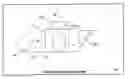
DESCRIPTION OF THE PREFERRED EMBODIMENTSThis invention is based on the idea of using multiple compaction plates of varying shapes and sizes to concentrate the force applied by a vibrating compaction plate to increase compaction rates of newly applied asphalt. Referring to figures, wherein like parts are designated with the same reference numerals and symbols, FIG. 1 is an illustration of a vibrating compaction device 10 with a primary compaction plate 12 and a secondary compaction plate 14, according to the invention. The primary compaction plate 12 is similar to those well-known in the art of asphalt compaction devices. A motor 16 or engine provides an up-and-down movement of the primary compaction plate 12 resulting in a vibration of the plate against the surface of the asphalt. One method of providing this up-and-down movement is to connect an eccentric 17 to the motor 16. A second eccentric 18 may be connected to a generator 19 which is, in turn, powered by the motor 16. In this manner, two eccentrics having different magnitudes of force may be synchronized. Alternatively, the two eccentrics may be connected by a shaft, with the second eccentric free-turning until it is hydraulically locked to the shaft. Additionally, the use of two eccentrics 17,18 may provide a reinforcing downward force while reducing or eliminating lateral force imparted to the asphalt compaction device.
The vibrating compaction device 10 may be rotated to bring the secondary compaction plate 14 in contact with the surface of the asphalt. In this embodiment of the invention, the secondary compaction plate is the same width as the primary compaction plate 12 but has a smaller length resulting in a small footprint. The motor 16 continues to produce a force equivalent to that normally applied through the primary compaction plate. However, since the footprint of the secondary compaction plate has a smaller contact area, the force exerted by the vibrating compaction device 10 is concentrated into a smaller area. In this manner, the ability of the vibrating compaction device 10 to compact the asphalt is increased, resulting in a higher compaction rate than can be achieved using the primary compaction plate 12.
Alternatively, the primary compaction plate 12 may be integrated with the secondary compaction plate 14 to form a unified compaction plate with a first and second surface. Here, the second surface is affixed to the first surface in a manner that forms a 135 degree angle between the two surfaces. However, the invention is not limited to any specific angle and may include an angle equal to or greater than 90 degrees and less than or equal to 180 degrees.
FIG. 1 also illustrates a tertiary compaction plate 20. In this embodiment of the invention, the tertiary compaction plate 20 has a width which is less than that of the primary compaction plate 12. Additionally, the tertiary plate may be formed in the shape of a semi-circle, an ellipse, a free-form shape, a triangle, or other polygon. Because the surface area of the tertiary compaction plate 20 is less than that of the primary compaction plate 10 and the secondary compaction plate, the tertiary compaction plate 20 may be used to apply even more force to the surface of the asphalt, thus increasing the rate of compaction. The non-traditional shape of the tertiary compaction plate 20 may be used to concentrate the force of the vibrating compaction device 10 along a focused path, such as a seam or newly filled-in trench. In an alternate embodiment of the invention, the secondary compaction plate may also include a non-traditional shape such as a semi-circle, ellipse, free-form shape, triangle, or other polygon. Additionally, the primary compaction plate 10 may include a plurality of surfaces including a primary, secondary, and tertiary surface. The angle formed by the tertiary surface and the primary surface may be greater than or equal to 90 degrees and less than or equal to 180 degrees.
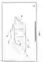
FIG. 2 is an illustration of a vibrating compaction device 10 with a secondary compaction plate 14 that can be extended and retracted with respect to the primary compaction plate 12. In this embodiment of the invention, the width of the secondary compaction plate 14 is the same as that of the primary compaction plate 12. However, the secondary compaction plate 14 may assume any width, either less than, equal to, or greater than that of the primary compaction plate. Likewise, while this embodiment of the invention includes a rectangular secondary compaction plate 14, the secondary compaction plate 14 may assume any shape. The result is that the secondary compaction plate 14 may be extended away from the primary compaction plate resulting in a focused application of the vibrating compaction device's downward force. Additionally, the secondary compaction plate 14 may be retracted so that its application surface (side facing the asphalt) is flush with or recessed above that of the primary compaction plate.
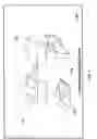
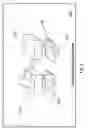
FIG. 3 is an illustration of an articulated vibrating compaction device 100 with a pair of primary compaction plates 112 and a secondary compaction plate 114, according to the invention. In this embodiment of the invention, the articulated segments 115 are used to steer the articulate vibrating compaction device. A first primary compaction plate 112a may be rotated that the secondary compaction plate 114 is applied to the surface to be compacted, as illustrated in FIG. 4. Additionally, the articulated vibrating compaction device 100 may include additional secondary compaction plates or tertiary compaction plates 118.
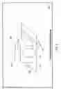
FIG. 5 is an illustration of an articulated vibrating compaction device 100 with a secondary compaction plate 114 that can be extended and retracted with respect to one of the primary compaction plates 112. While this embodiment of the invention includes a rectangular secondary compaction plate 114, the secondary compaction plate 114 may assume any usable shape. The result is that the secondary compaction plate 114 may be extended away from the primary compaction plate resulting in a focused application of the vibrating compaction device's downward force. Additionally, the secondary compaction plate 114 may be retracted so that its application surface (side facing the asphalt) is flush with or recessed above that of the primary compaction plate.
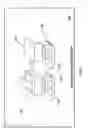
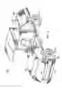
Yet another embodiment of the invention is illustrated in FIG. 6. Here, an articulated vibrating compaction device 200 includes a primary compaction plate 202 connected to an eccentric roller 204 located in a first articulated segment 206. As the eccentric roller 204 rotates, it imparts an up-and-down movement to the primary compaction plate 202 resulting in a vibration of the plate against the surface of the asphalt (not shown). A user may steer the articulated vibrating compaction device 200 by rotating the first articulated segment 206 relative to a second articulated segment 208. Locomotion is provided by a pulling motion of the primary compaction plate 202 as it is eccentrically vibrated.
A first set of pneumatic tires 210 may be placed adjacent to the primary compaction plate. These tires may provide compaction of the asphalt adjacent to the area being compacted by the primary compaction plate 202. Additionally, these tires may prevent asphalt which is being compacted by the primary compaction plate from spreading away from the sides of the primary compaction plate. This prevents a bow wave of asphalt from forming along the sides of the path of the articulated vibration compaction device 200. Additionally, this first set of pneumatic tires 210 may assist in steering the articulated vibration compaction device.
The articulated vibrating compaction device 200 may include a secondary compaction plate 212 which can be rotated so as to come in contact with the surface of the asphalt. In this embodiment of the invention, the secondary compaction plate is the same width as the primary compaction plate 202 but has a smaller length resulting in a smaller area of compaction, while the eccentric roller 204 continues to produce a force equivalent to that normally applied through the primary compaction plate 202. However, since the footprint of the secondary compaction plate is smaller, the force exerted by the articulated vibrating compaction device 200 is concentrated into a smaller area. In this manner, the ability of the articulated vibrating compaction device 200 to compact the asphalt is increased, resulting in a higher compaction rate than can be achieved using the primary compaction plate 202.
In one embodiment of the invention, the primary compaction plate 202 may be integrated with the secondary compaction plate 212 to form a unified compaction plate with a first and second surface. Here, the second surface is affixed to the first surface in a manner that forms a 135 degree angle between the two surfaces. However, the invention is not limited to any specific angle and may include an angle equal to or greater than 90 degrees and less than or equal to 180 degrees.
A second set of pneumatic tires 214 may be included in the second articulated segment 208. This second set of tires may be used to provide auxiliary compaction. Additionally, the second set of tires may assist in the steering of the articulated vibrating compaction device 200. In yet another embodiment of the invention, a second primary compaction plate, with or without another secondary compaction plate, may be included in the second articulated segment as well.
Those skilled in the art of making asphalt compaction systems may develop other embodiments of the present invention. However, the terms and expressions which have been employed in the foregoing specification are used therein as terms of description and not of limitation, and there is no intention in the use of such terms and expressions of excluding equivalents of the features shown and described or portions thereof, it being recognized that the scope of the invention is defined and limited only by the claims which follow.
Claims
1. An articulated vibrating compaction device, comprising:
a first segment including a first vibration source adapted to produce a first oscillating force and a first primary compaction plate adapted to receive the first oscillating force from the first vibration source; and
a second segment including a first set of pneumatic tires,
wherein the first primary compaction plate includes a first surface adapted to transmit the first oscillating force to a surface of a material and a second surface disparate from the first surface adapted to concentrate the oscillating force and to transmit the oscillating force to a surface of material.
2. (canceled)
3. (canceled)
4. The articulated vibrating compaction device of claim 3, wherein the second surface is adapted to selectively extend below the first surface.
5. The articulated vibrating compaction device of claim 4, wherein the second surface is further adapted to selectively retract above the first surface.
6. The articulated vibrating compaction device of claim 1, wherein the first segment further comprises a second set of pneumatic tires.
7. The articulated vibrating compaction device of claim 1, wherein the second segment further comprises a second vibration source adapted to produce a second oscillating force and a second primary compaction plate adapted to receive the second oscillating force from the second vibration source.
8. (canceled)
9. The articulated vibrating compaction device of claim 1, wherein the first vibration source includes a first eccentric motion device.
10. The articulated vibrating compaction device of claim 9, wherein the first vibration source includes a second eccentric motion device.
11. The articulated vibrating compaction device of claim 10, wherein the first eccentric motion device and the second eccentric motion device are adapted to produce a complementary downward force.
12. The articulated vibrating compaction device of claim 10, wherein the first eccentric motion device and the second eccentric motion device are adapted to impart no lateral motion to the articulated vibrating compaction device.
Images & Drawings included:
Sources:
- United States Patent and Trademark Office - verify current appl. status at the USPTO↗
Recent applications in this class:
- » 20250163656 2025-05-22
PLATE COMPACTOR - » 20240410119 2024-12-12
Vibrator Mechanism Usable With A Concrete Finishing Tool - » 20240141600 2024-05-02
Breather for vibration generating device - » 20230374741 2023-11-23
Plate compactor - » 20230121043 2023-04-20
MULTI-PURPOSE VIBRATORY CONCRETE TOOL - » 20220010505 2022-01-13
Plate compactor - » 20220010504 2022-01-13
Plate compactor - » 20210189665 2021-06-24
Vibrating float tool - » 20210062437 2021-03-04
Automatic vibrator assembly usable with a concrete finishing tool - » 20190145061 2019-05-16
RIG MOUNTED COMPACTOR