Grinding wheel spindle
US20060286908A1
2006-12-21
10/559,582
2004-12-06
Abstract:
A spindle for a grinding wheel which is to grind re-entrant cams on camshafts is described, comprising a drive motor, a shaft extending from the motor at the end of which is mounted a grinding wheel, and a rigid elongate casing extending from the motor and encasing the shaft. The length of the shaft and casing is selected to be at least as long as the axial length of cam shafts to be ground by the wheel. The shaft is carried in three hydrostatic bearings. One bearing is located near the grinding wheel at the end of the rigid casing remote from the motor. The assembly increases the shaft stiffness and its resistance to bending. A second bearing is located at the inboard end of the shaft and the third bearing is located within the motor at the far end of the shaft. The length of the rotor-bearing part is shorter than the external part of the shaft, which is constructed so that the stiffness and the support of the shorter part of the shaft dictate that the bending resonance of the longer external part is above the critical spindle rotational frequency. The motor housing is symmetrical and includes a water cooling jacket in which water follows a helical path around the motor, to avoid cooling one side of the motor more than another. The spindle is constructed to be axisymmetrical, so that any heat generated within the bearings dissipates radially and uniformly into the surrounding material. Oil is supplied under pressure to the bearings by a pump from a reservoir to which oil returns from the bearings. The oil is heated in each bearing and the heated oil drains into lower regions of the enclosure formed by the shaft casing and motor housing. The lower regions of this enclosure constitute a separate oil collection box mounted so as not to strain the shaft. A thermal barrier is provided between the upper and lower regions of the enclosure. During assembly the internal bores of two of the bearings are initially aligned and the third bearing is adjusted radially to bring all three bores into alignment.
Inventors:
- James Andrew Chaundler 1 🇬🇧 Olney, United Kingdom
- Walter Maximillian Markus Knuefermann 1 🇬🇧 Bedford, United Kingdom
Interested in similar patents?
Get notified when new applications in this technology area are published.
Classification:
B24B19/12 » CPC main
Single-purpose machines or devices for particular grinding operations not covered by any other main group for grinding non-circular cross-sections, e.g. shafts of elliptical or polygonal cross-section for grinding cams or camshafts
B24B41/04 » CPC further
Component parts such as frames, beds, carriages, headstocks Headstocks; Working-spindles; Features relating thereto
B24B7/00 IPC
Machines or devices designed for grinding plane surfaces on work, including polishing plane glass surfaces; Accessories therefor
Description
BACKGROUNDAutomotive engine designers have realised that a better performing engine can be achieved by modification of the camshaft lift profile. Thus the profile of that part of the cam which controls the actual opening and closing of the valve, is modified from a conventional flat or convex shape so as to possess a concave region. A camshaft of this type is known as having a re-entrant profile.
This type of profile manifests itself on the cam lobe as a depression in the lift/closure flank of the cam, which can only be produced with a grinding wheel whose external radius is the same as, or more preferably smaller than, the minimum radius of the cam form. Non re-entrant cam profiles can of course be ground with wheels of unlimited radius.
A number of issues are faced when designing grinding wheel spindles for this task;
-
- 1. Due to the small grinding wheel diameter, the spindle speed has to be proportionally higher to maintain a satisfactory wheel surface speed.
- 2. The grinding wheel must be capable of reaching the base circle diameter of each cam lobe, and in particular a cam lobe at the end of a camshaft remote from the spindle housing, while allowing the tips of other lobes to rotate clear of the spindle body is situated parallel to the camshaft. Therefore the spindle shaft is restricted in diameter to allow this clearance.
It is therefore necessary for the rotating shaft to be long, to be of small diameter and to be able to run at high rotational speeds.
Spindle design considerations dictate that the first resonant bending mode for a rotating shaft should reside beyond the maximum spindle rotating frequency. This arises from the observation that as spindle speed approaches its resonant frequency, resonance can be excited and spindle performance will be affected, often to the point of failure.
Hitherto this problem has usually been avoided by arranging that the resonant frequency of the spindle is as high as possible. Conventionally this has been achieved by using shafts which are short in axial length and have as large a diameter as is practical.
This is the very antithesis of the requirements for a grinding wheel spindle which is adapted to grind re-entrant cam profiles.
SUMMARY OF INVENTIONAccording to the present invention there is provided a spindle for a grinding wheel which is to grind re-entrant cams on camshafts comprising a drive motor, a shaft extending from the motor at the end of which is mounted a grinding wheel, and a rigid elongate casing extending from the motor and encasing the shaft, wherein the length of the shaft and casing is selected to be at least as long as the axial length of cam shafts to be ground by the wheel, the shaft is carried in three bearings each of which is a hydrostatic bearing, and one of the bearings is located near the end of the shaft carrying the grinding wheel so as to be at the end of the rigid casing remote from the motor, thereby to increase the shaft stiffness and increase its resistance to bending.
A second bearing may be located at the inboard end of the external part of the shaft, and the third bearing is located within the motor at the said other end of the shaft.
Typically the shaft is constructed so as to have at least two different diameters, and that part of the shaft which extends within the motor has a greater diameter than does that part of the shaft which extends axially externally therefrom.
The grinding wheel is preferably demountably fixed to the shaft.
The motor is usually an electric motor, and the stator of the motor is preferably secured within a rigid housing.
The non-rotating element of each of the three bearings is preferably secured within either the rigid elongate casing or the rigid motor housing.
According to a preferred aspect of the invention the axial length of the rotor-bearing part of the shaft is shorter than the external part of the shaft, and the shaft is constructed so that the stiffness and the support of the shorter part of the shaft situated between the second and third bearings dictate that the bending resonance of the longer external part is above the critical spindle rotational frequency
Preferably a symmetrical design of housing is employed for the motor.
As already stated, traditionally a grinding wheel spindle shaft has only been supported by two bearings and therefore bearing alignment has not been an issue. However, if three bearings are to be employed, alignment of the three bearings is very important. Where hydrostatic bearings are involved this is a very real problem since typically hydrostatic bearings have radial clearances (and therefore an oil film thickness) of the order of 25 microns, and if vibration is not to be introduced due to misalignment, any adjustment mechanism to achieve alignment needs to be capable of microscopic movements much smaller than the hydrostatic film thickness.
According therefore to another aspect of the present invention, during assembly the internal bores of two of the bearings are initially aligned and then the third bearing is then adjusted radially to bring all three bores into alignment.
However, alignment of the bearings is not restricted to ensuring their alignment during assembly, since at the high speeds required of grinding processes using small wheels, considerable heat can be generated within the bearings, and the spindle can also become heated by heat from the grinding wheel at one end and the electric motor (when under load) at the other end. This can result in variations in the spindle temperature in a non-axisymmetrical manner, resulting in bending due to differential thermal expansion taking place. This can result in misalignment of the spindle shaft and the bearings. This is particularly the case if the differential thermal expansion is occurring in different radial regions of the spindle structure.
Using a Symmetrical Design of Housing for the Motor Assists
Preferably the motor housing includes a water cooling jacket in which water is forced to follow a helical path around the motor, so as to avoid cooling one side of the motor more than another.
Preferably the spindle is constructed to be axisymmetrical, so that any heat generated within the bearings dissipates radially into the surrounding material in a uniform manner, so that in use the spindle housing will tend to warm up and cool down uniformly, and therefore expand and contract uniformly.
In use, oil is supplied under pressure hydrostatic to the bearings by a pump which draws oil from a reservoir to which oil returns from the bearings the oil becomes heated in each bearing and the heated oil drains into lower regions of the enclosure formed by the rigid elongate shaft casing and the motor housing. As a result the lower regions of the enclosure can become heated in use to a higher temperature then the upper regions thereof
This can result in bending and distortion of the spindle housing which again can cause misalignment of the bearings and can impart a strain on the spindle shaft.
In order to overcome the potential for distortion due to a hot zone being created in the lower regions of the spindle housing the lower regions of the enclosure are preferably formed as a separate oil collection box which is mounted to the remainder of the enclosure in such a manner that it will not impart a strain on the spindle shaft.
In order to reduce the transfer of heat to the bearings and upper regions of the enclosure a thermal barrier may be provided between the said lower regions and the remainder of the enclosure to reduce the transfer of heat from the hot oil to the upper regions of the enclosure and thereby prevent thermally induced misalignment of the three bearings and any strain on the spindle shaft caused by any such misalignment.
The invention will now be described by way of example with reference to the accompanying drawings in which:
FIGS. 1(a) and (b) illustrate how conventional profile and re-entrant profile cam can be ground,
FIG. 2 illustrates how the spindle shaft diameter is restricted where the workpiece contains regions of differing radial extent as in the case of cams along an engine camshaft,
FIG. 3 illustrates the axial space required for camshaft clearance,
FIG. 4 illustrates diagrammatically how the spindle shaft can be supported by three bearings (instead of the conventional two),
FIG. 5 illustrates diagrammatically how cooling fluid can be made to flow in a helical path around the spindle drive motor and,
FIG. 6 shows how oil leaves a hydrostatic bearing.
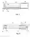
As shown in FIG. 1(a) a conventional cam profile 10 which contains no re-entrant (concave curvature) region can be ground using a relatively large diameter grinding wheel 12. Where (as is usual) the wheel diameter is considerably greater than the diameter of the spindle and drive motor, the wheel can be positioned anywhere along the length of a camshaft workpiece without there being any risk that the spindle or motor will be engaged by any part of a rotating cam.
The situation is rather different when grinding re-entrant cam profiles such as shown in FIG. 1(b). Here the diameter of the grinding wheel 14 must be such that it can enter the region of “concave” curvature 16,18 around the profile 20, to grind each curved face without simultaneously grinding away adjoining larger radiused regions of the profile—as would occur if a larger diameter wheel (such as 12 in FIG. 1(a)) were to be used.
It has been proposed to use two grinding wheels and to grind re-entrant profiles such as 20, by first using a larger wheel such as in FIG. 1(a) to form a non re-entrant profile (or partly re-entrant to the extent that the diameter of the larger wheel will allow) and then to use a smaller wheel such as shown in FIG. 1(b) to grind the re-entrant (concave) regions 16, 18.
However, this presents problems where there is a requirement for significantly smaller radius re-entrance as has been a feature of such cams during the last 5 years or so. Conformed radius of 50 mm have been a standard required and latterly there is a requirement for radius as small as 10 mm cams. Correspondingly smaller diameter wheels therefore have to be employed. The problem is demonstrated in FIG. 2, which shows how the cams do not all protrude in the one radial direction from the camshaft, and the base circle region 22 of one cam 23 can coincide with the tip 24 of another cam 25, albeit axially distant from the former. The wheel diameter is denoted by 26 and the wheel is shown mounted on a shaft 27. The diameter of the wheel is such as to be capable of grinding the desired radius of curvature of the re-entrancy in the cam lobe.
In order to follow the cam lobe surface as the camshaft rotates about its axis 28, the wheel axis 30 has to move towards and away from the camshaft axis 28 during the grinding process, typically under computer control in manner known per se. This is achieved by moving the wheelhead 32 in the forward and backward directions indicated by arrow 34. However, as will be seen with particular reference to FIG. 3, when the wheelhead 32 has moved to the right in FIG. 2, so that the wheel 26 can grind the base circle region 22 of a cam 23, it is important that the spindle housing 36 surrounding the shaft 27 does not interfere with the tips of other cams such as tip 24 of cam 25 in FIG. 2. This puts a constraint on the cross section size of the spindle housing 36.
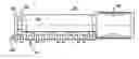
FIG. 3 shows the drive motor housing 38 which is larger in diameter than the spindle housing 36. This demonstrates that the spindle needs to extend axially to the left of the drive motor housing 38 by a least the axial length of the camshaft 40, so that the housing 38 will not interfere with the rotating cams. The spindle shaft 27 therefore has to be much longer than the case where the wheel diameter is significantly greater than that of the spindle housing 36 and drive motor housing 38. (It will be appreciated that where a larger diameter wheel is involved the shaft 27 need only protrude from the drive motor housing 38 by a sufficient length to allow the wheel to be mounted thereon). Since the spindle shaft 27 now needs to be as long as the workpiece 40, and the spindle and shaft are constrained in diameter for the reasons given above, the invention proposes the use of the third bearing as shown in FIG. 4, so as to stiffen the shaft.
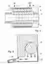
In FIG. 4 the rotor 40 can be seen mounted on, or formed integrally with, part of the spindle shaft 27 and the small diameter grinding wheel 26 is shown mounted on the extreme left hand (outboard) end of the shaft. The latter is supported by three hydrostatic bearings 44,46,48. The bearings 44 and 46 are located at opposite ends of the rotor 40 and the outer race of bearing 44 is mounted within the right hand end of the housing 38 which houses the stator (not shown) of the motor.
The bearing 48 is located adjacent to the grinding wheel while bearings 44 and 46 are positioned either side of the rotor 40,
The outer race of bearing 48 is secured within the spindle body 36 while the outer race of bearing 46 is located at the interface between the spindle body 36 and the motor housing 38, and also forms the location reference between the two.
During manufacture two of the bearings are first aligned, and then the third bearing is adjusted radially so as to accurately align with the other two bearings, so that the shaft 27 runs true.
To facilitate a comparison of FIGS. 3 and 4 the housings 36, 38 are shown in dotted outline in FIG. 4
More detail of the motor is shown in FIG. 5 which shows the shaft 27, rotor 40, stator 50 and housing 38. Around the stator is a cylindrical coolant jacket 52 through which cooling liquid (typically water) is caused to flow from an inlet 54 to an outlet 56. In so doing it is forced to traverse a helical path denoted in dotted outline at 58, so that there is no short straight path between inlet and outlet. In this way heat is removed in a generally uniform manner from the stator 50 and the housing 38 and no one region of the housing or stator should become hotter than any other region thereof.
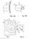
FIG. 6 shows how an oil collection chamber 60 can be fitted below a hydrostatic bearing housing 62 so as to collect oil under gravity as it leaves the bearing. By incorporating a seal 64 composed of poor thermal material between the chamber 60 and the housing 62, to form a thermal break, so any heat contained in the oil will not heat up the lower part of the housing 62 relative to the upper part thereof, as could otherwise happen, resulting in possible distortion of the housing 62. Oil leaves the chamber 60 via passage 66 to return to a reservoir (not shown) which may include an oil cooler.
Claims
1. A spindle for a grinding wheel which is to grind re-entrant cams on camshafts comprising a shaft at one end of which is mounted the grinding wheel, drive means for driving the other end of the shaft, and a rigid elongate casing extending axially from the drive means and encasing the shaft, characterised in that the drive means is an electric motor, and in that the length of the shaft and casing is selected to be at least as long as the axial length of a camshaft to be ground by the wheel, the shaft being carried in three hydrostatic bearings, one of which is located near said one end of the shaft so as to be at the end of the rigid casing remote from the motor, thereby to increase the shaft stiffness and increase its resistance to bending, the two other bearings disposed on opposite sides of the motor.
2. A spindle as claimed in claim 1 wherein the second bearing is located at the inboard end of the external part of the shaft, and the third bearing is located within the motor at said other end of the shaft.
3. A spindle as claimed in claim 1 or claim 2 wherein the stator of the motor is secured within a rigid housing and the non-rotating element of each of the three bearings is secured within either the rigid elongate casing or the rigid motor housing.
4. A spindle as claimed in claim 2 or claim 3 wherein the axial length of the part of the shaft which carries the rotor of the motor is shorter than the external part of the shaft, the shaft being constructed so that the stiffness and the support of the shorter part of the shaft situated between the second and third bearings dictate that the bending resonance of the longer external part is above the critical spindle rotational frequency.
5. A spindle as claimed in any one of claims l to 4 in which a symmetrical design of housing is employed for the motor.
6. A spindle as claimed in claim 5 wherein the motor housing includes a water cooling jacket in which water is forced to follow a helical path around the motor, so as to avoid cooling one side of the motor more than another.
7. A spindle as claimed in any one of claims 1 to 6 wherein the spindle is constructed to be axisymmetrical, so that any heat generated within the bearings dissipates radially into the surrounding material in a uniform manner, so that in use the spindle casing will tend to warm up and cool down uniformly, and therefore expand and contract uniformly.
8. A spindle as claimed in any one of claims 1 to 7 in which, in use, oil is supplied under pressure to the bearings by a pump which draws oil from a reservoir to which oil returns from the bearings.
9. A spindle as claimed in claim 8 comprising an enclosure formed by the rigid casing and a housing for the motor, wherein oil heated in use in each bearing drains into the lower regions of the enclosure and can thereby become heated to a higher temperature then the upper regions thereof.
10. A spindle as claimed in claim 9 wherein the lower regions of the enclosure are formed as a separate oil collection box which is mounted to the remainder of the enclosure in such a manner that it will not impart a strain on the spindle shaft.
11. A spindle as claimed in claim 9 or claim 10 wherein a thermal barrier is provided between the said lower regions and the remainder of the enclosure to reduce the transfer of heat from the hot oil to the upper regions of the enclosure and thereby prevent thermally induced misalignment of the three bearings and any strain on the spindle shaft caused by any such misalignment.
12. A method of constructing a spindle as claimed in claim 2 wherein during assembly the internal bores of two of the bearings are initially aligned and the third bearing is adjusted radially to bring all three bores into alignment.
Images & Drawings included:
Sources:
- United States Patent and Trademark Office - verify current appl. status at the USPTO↗
Similar patent applications:
Recent applications in this class:
- » 20170266776 2017-09-21
Honing method and inner cam with C-shaped cross section - » 20170157729 2017-06-08
Method for producing a camshaft assembly - » 20170144264 2017-05-25
Cam grinding machine and cam grinding method - » 20160297050 2016-10-13
Accommodating assembly for the grinding of a camshaft and method for grinding the camshaft - » 20120131790 2012-05-31
CAM GRINDING DEVICE - » 20100233939 2010-09-16
Method of and apparatus for grinding cams of a camshaft - » 20090223049 2009-09-10
Method and device for the finish machining of composite camshafts and eccentric shafts - » 20080188161 2008-08-07
METHOD AND SYSTEM FOR FORMING A WORKPIECE - » 20080173128 2008-07-24
Shaft with functional bodies such as camshafts for internal combustion engines, method of producing them and engines equipped therewith - » 20070264913 2007-11-15
Method for grinding of cam profiles