Handhold wireless device
US20060287011A1
2006-12-21
11/237,677
2005-09-29
✅ Patent granted
US 7,596,394 B2
2009-09-29
-
-
CongVan Tran
2025-10-13
Abstract:
The present invention relates to a handhold wireless device, comprising a main body and a hanging frame; wherein the two sides of the main body are each provided with a guiding trench having a first end and a second end and for allowing the hanging frame sliding between the two ends. When the frame is slid to the first end, the frame is accommodated in the trench, and when the frame is slid to the second end, the frame is extended out the main body for hanging. When the frame is slid to the second end, the wireless device can be hung on a hanger. Alternatively, when the frame is at the second end, it can be rotated at an angle to be a supporter of the device to stand.
Assignee:
- LITE-ON IT CORPORATION 270 🇹🇼 Taipei, Taiwan
Interested in similar patents?
Get notified when new applications in this technology area are published.
Classification:
H04M1/0235 » CPC main
Substation equipment, e.g. for use by subscribers; Constructional features of telephone sets; Portable telephone sets, e.g. cordless phones, mobile phones or bar type handsets; Portable telephones comprising a plurality of mechanically joined movable body parts, e.g. hinged housings characterized by the relative motions of the body parts Slidable or telescopic telephones, i.e. with a relative translation movement of the body parts; Telephones using a combination of translation and other relative motions of the body parts
H04M1/0214 » CPC further
Substation equipment, e.g. for use by subscribers; Constructional features of telephone sets; Portable telephone sets, e.g. cordless phones, mobile phones or bar type handsets; Portable telephones comprising a plurality of mechanically joined movable body parts, e.g. hinged housings characterized by the relative motions of the body parts Foldable telephones, i.e. with body parts pivoting to an open position around an axis parallel to the plane they define in closed position
H04M1/04 » CPC further
Substation equipment, e.g. for use by subscribers; Constructional features of telephone sets Supports for telephone transmitters or receivers
H04M1/00 IPC
Substation equipment, e.g. for use by subscribers
Description
This Non-provisional application claims priority under 35 U.S.C. §119(a) on Patent Application No(s). 094120698 filed in Taiwan, Republic of China on June 21, 2005, the entire contents of which are thereby incorporated by reference.
FIELD OF THE INVENTIONThe present invention relates to a handhold wireless device, particularly to a handhold wireless device which is capable of hanging on a wall and standing on a plane.
DESCRIPTION OF RELATED ARTWith developing of remote control device, almost electronic apparatus such as television, video, stereo, and the like are controlled by using a wireless control device. Moreover, mobile phone is popular in the modern living. Such wireless devices are desired to be designed as thinner, lighter, and smaller as possible. Consequent, such wireless devices are not easy to find out after using since user always forgets where they put.
If there is any means on such wireless devices for hanging or standing, they would be hung on a wall or standing on a table or plane and thus can resolve the above problems.
SUMMARY OF THE INVENTIONThe one object of the present invention is to provide a handhold wireless device, which is capable of hanging on a wall or a door knob by using a hanging frame provided on a main body.
The other object of the present invention is to provide a handhold wireless device, which is capable of standing on a plane by rotating a hanging frame in a certain angle.
To achieve the above objects, the present invention provides a handhold wireless device which comprises a main body and a hanging frame; wherein the two sides of the main body are each provided with a guiding trench having a first end and a second end and for allowing the hanging frame sliding between the two ends. When the frame is slid to the first end, the frame is accommodated in the trench, and when the frame is slid to the second end, the frame is extended out the main body for hanging. Thereby, when the hanging frame is positioned at the second end, the wireless device can be hung on a hanger and the frame can further be rotated at an angle to be a supporter of the device to stand.
According to the present handhold wireless device, the hanging frame is in a form of U-type and its two ends are each provided with a pivot which can slide in the trench.
According to the present handhold wireless device, the guiding trench is further provided with an extrusion rib along its wall for lodging the hanging frame in.
According to the present handhold wireless device, the pivot is further provided with a neck part for lodging with the extrusion rib.
According to the present handhold wireless device, the main body or the hanging frame or the both are partly provided with or made from a magnet for attaching on a metal surface.
According to the present handhold wireless device, the hanging frame can further be rotated in an angle to be a supporter for allowing the device standing when the hanging frame is slid to the second end.
BRIEF DESCRIPTION OF DRAWINGSThe present invention is illustrated more detail by reference to the accompanying drawings, wherein:
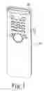
FIG. 1 is a schematic drawing of the handhold wireless device according to the present invention;
FIG. 2 is a side-viewing drawing of the present handhold wireless device in which the hanging frame is positioned at the first end of the trench;
FIG. 3 is a section drawing of the handhold wireless device shown in FIG. 2 along the line A-A;
FIG. 4 is a side-viewing drawing of the present handhold wireless device in which the hanging frame is positioned at the second end of the trench;
FIG. 5 is a section drawing of the handhold wireless device shown in FIG. 4 along the line A-A;
FIG. 6 is a side-viewing drawing of the present handhold wireless device in which the hanging frame stand on a plane; and
FIG. 7 is a schematic drawing of the present handhold wireless device in which the hanging frame is hung on a hanger.
DETAILED DESCRIPTION OF THE INVENTIONThe present invention is illustrated in more detail by reference the following embodiments which are only used for illustration without limiting the scope of the present invention.
Please refer to FIGS. 1-3. FIG. 1 is a schematic drawing of the handhold wireless device according to the present invention. FIG. 2 is a side-viewing drawing of the present handhold wireless device in which the hanging frame is positioned at the first end of the trench. FIG. 3 is a section drawing of the handhold wireless device shown in FIG. 2 along the line A-A.
As shown in FIG. 1 and FIG. 2, the handhold wireless device according to the present invention comprises a main body 10 and a hanging frame 20; wherein the two sides of the main body 10 are each provided with a guiding trench 11 having a first end and a second end and for allowing the hanging frame 20 sliding between the two ends. In the guiding trench, there further provides with an extrusion rib 12 along its wall for lodging said hanging frame in (as shown in FIG. 3).
The hanging frame 20 is in a form of U-type and its two ends are each provided with a pivot 22 which can slide in the trench. Also, the pivot 22 is further provided with a neck part 221 for lodging with the extrusion rib 12.
When the frame 20 is slid to the first end, the frame is accommodated in the trench 11, as shown in FIG. 2, and when the frame 20 is slid to the second end, the frame 20 is extended out the main body 10 for hanging, as shown in the FIG. 4.
Please also refer to FIGS. 4-7. FIG. 4 is a side-viewing drawing of the present handhold wireless device in which the hanging frame is positioned at the second end of the trench. FIG. 5 is a section drawing of the handhold wireless device shown in FIG. 4 along the line A-A. FIG. 6 is a side-viewing drawing of the present handhold wireless device in which the hanging frame stand on a plane. FIG. 7 is a schematic drawing of the present handhold wireless device in which the hanging frame is hung on a hanger.
According to the present invention, the handhold wireless device can be hung on a hanger 30 or a door knob through the use of the hanging frame 20 when the hanging frame 20 is slid to the second end of the trench 11, as shown in FIG. 7. Alternatively, the hanging frame 20 can further be rotated in an angle to be a supporter of the main body 10 to stand on table or any plane.
Moreover, the main body 10 or the hanging frame 20 or the both are partly provided with or made from a magnet 40, as shown in FIG. 2, for attaching on a metal surface such on a refrigerator.
While the present invention has been particularly shown and described with reference to exemplary embodiments thereof, it will be understood by those of ordinary skill in the art that various changes and modifications may be made therein without departing from the spirit and scope of the present invention as defined by the following claims.
Claims
What is claimed is:1. A handhold wireless device, comprising
a main body, the two sides of which are each provided with a guiding trench having a first end and a second end; and
a hanging frame, which is slid between the first and the second ends, wherein the frame is accommodated in the trench when it is slid to the first end, and the frame is extended out the main body for hanging when it is slid to the second end.
2. The handhold wireless device according to claim 1, wherein said hanging frame is in a form of a U-shape and two ends of the frame are each provided with a pivot.
3. The handhold wireless device according to claim 2, wherein said guiding trench is further provided with an extrusion rib along its wall for lodging said hanging frame in.
4. The handhold wireless device according to claim 3, wherein said pivot is further provided with a neck part for lodging with said extrusion rib.
5. The handhold wireless device according to claim 1, wherein said hanging frame is rotated in an angle to be a supporter for allowing the device standing when said hanging frame is slid to the second end.
6. The handhold wireless device according to claim 1, wherein said main body is partly provided with or made from a magnet for attaching on a metal surface.
7. The handhold wireless device according to claim 1, wherein said hanging frame is partly provided with or made from a magnet for attaching on a metal surface.
Images & Drawings included:


Sources:
- United States Patent and Trademark Office - verify current appl. status at the USPTO↗
Recent applications in this class:
- » 20250240359 2025-07-24
SLIDABLE AND ROLLABLE DEVICE AND DISPLAY DEVICE - » 20250211660 2025-06-26
ELECTRONIC DEVICE INCLUDING FLEXIBLE DISPLAY BUFFER STRUCTURE - » 20250047767 2025-02-06
CONVEYING A STATE OF AN ELECTRONIC DEVICE WHILE THE DISPLAY IS OFF - » 20250030788 2025-01-23
ELECTRONIC DEVICE COMPRISING ROLLABLE DISPLAY, AND METHOD FOR OPERATING SAME - » 20250023967 2025-01-16
SLIDABLE ELECTRONIC DEVICE COMPRISING FLEXIBLE DISPLAY - » 20240414250 2024-12-12
ELECTRONIC DEVICE COMPRISING FLEXIBLE DISPLAY AND METHOD FOR CONTROLLING ELECTRONIC DEVICE - » 20240267445 2024-08-08
ELECTRONIC DEVICE - » 20240267444 2024-08-08
Electronic device having antennas - » 20240223686 2024-07-04
ELECTRONIC DEVICE AND METHOD FOR CONTROLLING DRIVING OF MOTOR - » 20240129391 2024-04-18
Electronic Devices with Translating Flexible Displays and Corresponding Methods for Managing Display Position as a Function Content Presentation
Recent applications for this Assignee:
- » 20150206584 2015-07-23
CONTROLLING METHOD FOR SOLID STATE DRIVE WITH RESISTIVE RANDOM-ACCESS MEMORY - » 20150194133 2015-07-09
PORTABLE ELECTRONIC DEVICE WITH PROJECTING FUNCTION AND PROJECTING METHOD THEREOF - » 20150187398 2015-07-02
Control method for nonvolatile memory device with vertically stacked structure - » 20150186149 2015-07-02
Processing system of electronic device and operating method thereof with connected computer device - » 20150186052 2015-07-02
Storage device and data transmission control method thereof - » 20150185593 2015-07-02
Pico projection fixing module - » 20150124533 2015-05-07
Solid state storage device and sensing voltage setting method thereof - » 20150118957 2015-04-30
Near field communication system and method for providing an effective antenna that is adaptable for different antenna configurations and locations of a portable device - » 20150109859 2015-04-23
Electronic device with solid state drive and associated control method - » 20150109588 2015-04-23
Micro projector device and control method thereof