Structural assembly
US20070095484A1
2007-05-03
10/560,611
2004-06-21
Abstract:
A structural assembly for the construction of buildings and other types of structures where a covering is fixed to a frame by a removable seal. The seal is spring biased to secure the covering against the frame in at least two places. The system provides for quick assembly and with the use of different types of connectors and joiners, different types of structures of variable design can be formed for temporary or permanent use.
Interested in similar patents?
Get notified when new applications in this technology area are published.
Classification:
F16B5/0692 » CPC main
Joining sheets or plates, e.g. panels, to one another or to strips or bars parallel to them by means of clamps or clips joining flexible sheets to other sheets or plates or to strips or bars
A01G9/1407 » CPC further
Cultivation in receptacles, forcing-frames or greenhouses ; Edging for beds, lawn or the like; Greenhouses of flexible synthetic material
Y02A40/25 » CPC further
Adaptation technologies in agriculture, forestry, livestock or agroalimentary production in agriculture Greenhouse technology, e.g. cooling systems therefor
A47H1/00 IPC
Curtain suspension devices
A47H1/00 IPC
Curtains; Draperies
Description
FIELD OF INVENTIONThe present invention relates to building structures involving securing covering to a frame. The present invention has particular but not exclusive application for emergency and temporary shelters and greenhouses. Greenhouses are described in the body of the specification as an example of the present invention and are described in the specification by way of example only.
BACKGROUNDGreenhouses usually consist of a frame covered with shade cloth so to protect plants housed within the greenhouse from the weather, particularly the effects of the sun. The shade cloth is often attached by clips such as shown in U.S. Pat. No. 5,497,537, clasps as disclosed in U.S. Pat. No. 4,378,617, nail strips as shown in U.S. Pat. No. 4,974,298, or suspended on the frame by covering loops. Each of these different forms of securing the covering to the frame has problems. Where the covering is fastened at a fixed point, such as with clips and clasps the covering has a tendency to tear about the fastened point during high winds or storms. Some methods of fastening the covering also fail to maintain the stretched position of the shade cloth over the frame subsequently resulting in the frame not being adequately covered by the shade cloth.
U.S. Pat. No. 4,788,806 discloses a framework assembly with a molding strip locatable within a channel to fix a flexible covering. The molding strip is able to snap fit within the channel to fix the covering. The covering however can only be fixed one way and the channel and molding strip has only one orientation.
U.S. Pat. No. 4,233,790 discloses a fixing arrangement where there is a channel with longitudinally extending rigid bars along the channel walls and a locking member with two bars positioned so to complement the channel grooves formed by the rigid bars. Under stressful conditions the locking member may be dislodged and the covering loosened from the channel as the locking member does not clamp the covering against the channel wall and dislodgement of one portion of the locking member affects the positioning of other portions of the locking member.
OBJECT OF THE INVENTIONIt is an object of the present invention to provide an alternative means for securing a covering to a frame. It is a further object to provide an alternative structural assembly whereby a covering is secured to the frame and covers the frame to form a desired structure.
STATEMENT OF THE INVENTIONIn one aspect the present invention broadly resides in a system for securing a covering to a frame including
a longitudinal frame member with a longitudinally extending recess, said recess having a plurality of longitudinally extending ribs on each opposing face of the recess walls; and
a resiliently deformable sealing member having a substantially complementary profile to the recess;
wherein said covering is locatable between said recess and the inserted sealing member and secured in position by the outwardly directed spring bias of the inserted sealing member against the recess walls.
There are preferably two longitudinally extending ribs on each opposing inner face of the recess walls that can engage complementary grooves in the sealing member. The covering is preferably positioned so that it Is captured by both ribs on one recess face when the sealing member is inserted. The advantage of being captured by both of the ribs on one of the faces is that there are two securing points thereby reducing the tendency for slippage or tearing of the covering. The advantage of having ribs on both inner faces of the recess is that the frame member may be placed in either orientation relative to the covering during fastening.
The frame member is preferably substantially cylindrical to provide integral strength and surfaces without edges to avoid abrasive wear of the contacting covering.
The frame member is preferably connectable with other frame members. The frame member preferably has hollow ends or narrower diameter ends that provide for the fitting of connector members or other frame members with connectable ends.
The resiliently deformable sealing member is preferably made of plastics and designed to deform during insertion with a spring bias that has a tendency to push the outer surfaces of the sealing member against the recess wall faces. The sealing member preferably clamps the covering to the opposing recess wall because of the outwardly directed spring bias when the sealing member is inserted within the recess.
Preferably the sealing member has two relatively independent legs which are biased to moving outwardly. The legs are preferably independent to the extent that the legs operate substantially Independently. Each leg preferably has a spring bias directed outwardly and when inserted within the recess, each of the legs is disposed to abut the opposing recess wall surface thereby clamping the covering between the recess wall and the sealing member. Being resiliently deformable and having outwardly disposed spring biased legs, the sealing member can be easily removed and repositioned without damaging the sealing member.
The sealing member may be of any desired length or width but preferably with a substantially constant profile.
When inserted the sealing member is substantially flush with the cylindrical frame member.
The covering may be any sized portion of a suitable fabric including shade cloth, canvas and plastics material.
In another aspect the invention broadly resides in a structural assembly including
a plurality of longitudinal frame members, each of said frame members has a longitudinally extending recess, each of said recesses has a plurality of longitudinally extending ribs on each opposing face of the recess walls;
connector means for connecting the frame members;
one or more resiliently deformable sealing members, each of said sealing members has a substantially complementary profile to the recess; and
one or more coverings wherein each of said coverings is locatable between said recess and the inserted sealing member and secured in position by the outwardly directed spring bias of the inserted sealing, member against the recess walls.
The frame members, sealing member(s) and covering(s) are preferably as described in the above mentioned description. The connector means may include connector members such as a 90 degree joiner, a 120 degree joiner, a straight joiner, a three way joiner, a four way joiner, a spreader, an end adaptor, and one or more different types of brackets. Each of the (assembled) connector members preferably has a recess similar to the frame member. Each of the connector members preferably has a connector portion locatable within the open end of the frame member. The connector portion preferably forms an inner sleeve. The connector portion has a substantially cylindrical shape with one or more outwardly extending projections to abut the inner cylindrical surface of the frame member. The outwardly extending projections preferably are adapted to secure or lock against the inner surface of the frame member. The three way joiner, 120 degree joiner and 90 degree joiner may have an outer surface with a locator portion that is adapted to engage a complementary locator portion of another member thereby fixing the position of the members relative to each other. One locator portion preferably has two or more dimples while a complementary locator portion has two or more pins that can engage the dimples. Preferably the end adaptor has a locator portion with two or more pins.
With the frame member and the connector members, different types of structures can be formed. The different types of building structures include shade houses and greenhouses, shade tunnels, animal shelters, awnings, canopies, carports, temporary accommodation, emergency shelters, canopies on the back of trucks and bus shelters.
In a further aspect the invention broadly resides in a method of assembling a structure as described above including
building a frame with frame members and connecting members as described above;
positioning one or more covering members over the frame; and
inserting the sealing member to secure the covering member to the frame member.
The covering member is preferably sealed while tension is kept on the covering member.
The integrity of the frame may be maintained by bolting the frame members and connector members together to avoid accidental disassembly. An advantage of the system is that the assembly and disassembly can be relatively quick.
A variety of different structures may be formed with the abovementioned method. In one preferred embodiment the structure formed by the method is a modular structure wherein each module has a length and width not greater than approximately 6 metres and any one structure may comprise one or more modules.
In another aspect the invention broadly resides in a system for assembling a structure including
forming a frame with a plurality of longitudinal frame members, each of said frame members has a longitudinally extending recess, each of said recesses has a plurality of longitudinally extending ribs on each opposing face of the recess walls; connecting frame members with suitable connectors wherein the recesses are aligned for inserting a sealing member;
positioning a covering over the frame and inserting one or more resiliently deformable sealing members so that the covering is secured within the recess by the sealing members wherein each of said sealing members has a substantially complementary profile to the recess and an outwardly directed spring bias against the recess walls.
Structures can be made in a modular arrangement and two or more modules can be joined to form a structure of a desired size. Where the particular structure is longer or wider than 6 metres, the structure is formed by joining two or more modules. In this way, the use of modules provides easy and reproducible assembly for larger structures without compromising structural integrity and strength.
BRIEF DESCRIPTION OF THE DRAWINGSIn order that the present invention be more readily understood and put into practical effect, reference will now be made to the accompanying drawings wherein:
FIG. 1 is a cross-sectional view of the frame member of the preferred embodiment;
FIG. 2 is a diagrammatic view of the frame member with the seal;
FIG. 3a is a cross-sectional view of the seal;
FIGS. 3b and 3c are diagrammatic views of the seal;
FIG. 4 is a side view of a 120 degree joiner with joining frame members;
FIG. 5 is a cross-sectional view of the 120 degree joiner at A-A shown in FIG. 4;
FIG. 6 is a cross-sectional view of the 120 degree joiner at B-B shown in FIG. 4;
FIG. 7 is a diagrammatic view of a flange connecting bracket;
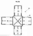
FIG. 8a is a diagrammatic view of a vertical four way joiner while FIG. 8b is a diagrammatic view of a flat four way joiner;
FIG. 9 is a side view of an end bracket;
FIG. 10 is an alternate side view of an end bracket;
FIG. 11 is a side view of a diagonal tube bracket;
FIG. 12 is an alternate side view of a diagonal tube bracket;
FIG. 13 is an end view of the diagonal tube bracket;
FIG. 14 is a diagrammatic view of an end adapter;
FIG. 15 is a side view of a 90 degree joiner,
FIG. 16 is a diagrammatic view of a three way joiner;
FIG. 17a is a diagrammatic view of a post bracket;
FIG. 17b is a diagrammatic view of an alternate door trim;
FIG. 18 is a diagrammatic view of the frame of a shelter;
FIG. 19a is a diagrammatic view of a fascia awning while FIG. 19b is an off-the-wall awning; and
FIG. 20 is a diagrammatic view of an emergency shelter.
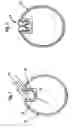
DETAILED DESCRIPTION OF THE PREFERRED EMBODIMENTIn FIGS. 1 and 2, there is shown a tubular frame member 10 with a longitudinal recess 11 in which the seal 12 can be located. The tubular frame member 10 is substantially cylindrical in shape. The longitudinal recess 11 is substantially rectangular in shape with two spaced apart ribs 13 on each of the opposing side walls 14, 15 with a first groove 16 formed between the two ribs 13 and a second groove 17 formed between recess base wall 18 and adjacent rib 13.
The seal 12 is also shown in FIG. 3a, 3b and 3c. The seal 12 has a top portion 21 and legs 22, 23. Legs 22, 23 are shaped so that when they are pressed together they deform but resume their initial shape in the absence of the deforming force. When there is a deforming force, legs 22 and 23 move together with bridge portions 24, 25 abutting. The lower portions 26, 27 of each leg 22, 23 respectively moves to fit within the recess 11. Each leg 22, 23 has projections 28, 29 that are shaped to complement grooves 16 and 17 within the recess 11. When the seal 12 is positioned within the recess 11, the projections 28, 29 engage grooves 16, 17 respectively, ribs 13 engage grooves 30 on either side of projection 28 and top portion 21 forms a seal with the outer surface of the frame member 10. Each of the legs 22,23 have an outwardly directed spring bias which when located within the recess 11 pushes against the corresponding recess side wall. The seal 12 is made of plastics preferably extruded PVC.
The frame member 10 is made of aluminum by an extruded process.
A 120 degree joiner 40 is shown in FIG. 4. The 120 degree joiner 40 comprises two connector sleeve portions 41, and a corner portion 42. The connector sleeve portions 41 have outwardly extending ribs 43 for abutting the inner surface of frame member 10. The connector sleeve portions 41 have a recess 44 that nests about recess 11 on the tubular frame member 10. The fifting of the recess 44 about recess 11 serves to prevent the 120 degree joiner 40 from rotating within the frame member 10. The corner portion 42 also has a recess portion 45. The recess portion 45 is in line with recess 44. The recess portion 45 has two ribs on each opposing sidewall surface and is similar in shape to recess 11. The recess portion 45 can accommodate the seal 12. Recess 44 is shown in FIG. 6 while recess portion 45 is shown in FIG. 5. The 120 degree portions 40 are typically used to form framework for roofs.
The 120 degree joiner 40 is cast-molded in two parts and assembled with guide pins and sockets. Apertures 51, 52 shown in FIG. 6 allow the two part 120 degree joiner 40 to be bolted together to maintain the assembled state. There are other corner joiners induding 106 degree joiner and 148 degree joiner.
In FIG. 7 there is shown a connector bracket 70 having a connector portion 71 and flange 72. The connector portion 71 is shaped to form a sleeve substantially surrounding the frame member 10. The flange 72 can serve as a window or door jamb or architrave.
FIG. 8a shows a vertical four way joiner 80 with four connector portions 81 and a corner portion 82. FIG. 8b shows a flat four way joiner 83 with four connector portions 84 and a corner portion 85. The connector portions 81, 84 are similar to the connector portions 41 described in the 120 degree joiners 40. The four way joiners 80, 83 are used to connect intersecting frame members during the construction of shelter.
FIGS. 9 and 10 show an end bracket 90 having a connector portion 91 and spreader portion 93. The connector portion 91 has longitudinally extending ribs 92 which can abut the inner wall of the frame member 10 when inserted within the frame member 10. The spreader portion 93 is substantially cup-shaped for supporting frame members 10. The end bracket 90 can be used to provide support and connection between horizontally and vertically displaced frame members 10.
FIGS. 11, 12 and 13 show a diagonal tube bracket 110 which has a connector portion 111 and a fastening portion 112. The connector portion 111 is cylindrical and can be positioned within frame member 10 while fastening portion 112 can be bolted to another suitable frame member by the fastening of a bolt through aperture 113 and another frame member or connector. The diagonal tube bracket 110 is useful when the cylindrically shaped frame member 10 needs to be fastened to a substantially flat or rectangular frame member.
An adaptor 140 is shown in FIG. 14 and has an adaptor portion 141 and a connector portion 142. The connector portion 142 is similar to connector portions of other bracket and joiner members. The connector portion 142 is insertable within the frame member 10 and has ribs 145 for abutting against the inner wall of the frame member 10. The connector portion 142 is substantially cylindrical in shape with a portion removed to allow the adaptor 140 to be positioned relative to the recess 11 of the frame member 10. The adaptor portion 141 has a circular wall 143 with two locating pins 144 that extend outwardly. The adaptor 140 is designed for use with a frame member 10 to abut against a joiner or bracket with corresponding locating sockets.
In FIG. 15 there is shown a 90 degree joiner 150 with connector portions 151 and corner portion 152. The connector portions 151 are insertable within frame members 10 and are similar to connector portions of other bracket and joiner members. The corner portion 152 has a locator portion 153 that has a circular wall 154 with four locating sockets 155. The locator portion 153 has four spaced apart locator sockets 155 that allow the adaptor 140 to be positioned in one of two alternate 90 degree positions.
In FIG. 16 is shown a three-way joiner 160 where there are three connector portions 161 and a central portion 162. The three-way joiner 160 may have connector portions 161 in any suitable arrangement. The connector portions 161 are similar to connector portions of other bracket and joiner members. Central portion 162 may have a locator portion similar to the locator portion 153 shown in FIG. 15.
A post bracket 170 is shown in FIG. 17a and comprises a post portion 171 and a bracket portion 172. The post portion 171 is an elongate portion with a rectangular cross-section while the bracket portion 172 has a substantially U-shaped bracket sharing a base wall 173 with the post portion 171. The post bracket 170 is used to attach to the length of the frame members 10 to provide a flat surface for doorway frames and window architraves and lintels.
In FIG. 17b there is shown an alternate door trim 175 where the covering is sandwiched between the trim 175 and the frame 176. The trim 175 is fastened to the frame 176 by fasteners at flange 177 and held in position by hook-shaped portion 178.
There may be other types of connectors such as other multi-way joiners and U-shaped brackets.
From these frame members, connectors and joiners different types of structures can be formed. These include by way of example, shelters (FIGS. 18 and 20) and awnings (FIGS. 19a and 19b). Frame members, connectors and joiners may be used to produce other types of structures including patio awning, greenhouses or shade houses, pergolas and car ports. As well the same structure may have different designs such as patio awning with bull nose section.
With reference to FIG. 18 there is shown a shelter 181 with frame members 10 forming uprights, roof frames and base frames. The frame members 10 are connected by three way joiners 160, 120 degree joiners 40, 148 degree joiners and adapters 140. The frame is covered with a shade cloth to form a greenhouse. In contrast, a similar frame is covered with canvas 201 and fly screen mesh 202 in FIG. 20 to provide an emergency or temporary shelter 200. Permanent doors may be installed in the shelters with the use of post brackets and flange brackets.
In FIGS. 19a and 19b, there is shown two different types of awnings for screening a window from the effects of the sun. FIG. 19a shows a fascia type awning 190 whereas FIG. 19b shows an off-the-wall type awning 191. The frame for the awnings comprises frame members 10 connected by 90 degree joiners. Shade cloth 192 is stretched across the frame and fixed in position by seal 12.
When the frame has been constructed, covering such as shade cloth, canvass, plastic sheeting or any other suitable material may be inserted within the recess and fixed in position by the seal. The covering is clamped in position by the engagement of ribs 13 of the frame member 10 with recesses 30 on the seal 12. With two ribs 13 either side of recess side walls 14, 15 the covering is clamped in two positions irrespective of which side the covering is placed. As a consequence the resulting structure can be assembled quickly and with the covering securely fastened.
AdvantagesThe advantages of the present invention include the quick assembly of a suitable frame with the rapid fixing of covering the frame by a removable seal. With the different types of connectors and joiners, different types of structures of variable design can be formed for temporary or permanent use.
VariationsIt will of course be realised that while the foregoing has been given by way of illustrative example of this invention, all such and other modifications and variations thereto as would be apparent to persons skilled in the art are deemed to fall within the broad scope and ambit of this invention as is herein set forth.
Throughout the description and claims this specification the word “comprise” and variations of that word such as “comprises” and “comprising”, are not intended to exclude other additives, components, integers or steps.
Claims
1. A system for securing a covering to a frame including
a longitudinal frame member with a longitudinally extending recess, said recess having a plurality of longitudinally extending ribs on each opposing face of the recess walls; and
a resiliently deformable sealing member having a substantially complementary profile to the recess; wherein said covering is locatable between said recess and the inserted sealing member and secured in position by the outwardly directed spring bias of the inserted sealing member against the recess walls.
2. A system as claimed in claim 1 wherein there are two longitudinally extending ribs on each opposing inner face of the recess walls that can engage complementary grooves in the sealing member, thereby providing for the securing of the covering by both ribs on one recess face when the sealing member is inserted.
3. A system as claimed in claim 1 wherein the frame member is preferably substantially cylindrical to provide integral strength and surfaces without edges to avoid abrasive wear of the contacting covering.
4. A system as claimed in claim 1 wherein the sealing member has two relatively independent legs which are biased to moving outwardly and operate substantially independently.
5. A structural assembly including
a plurality of longitudinal frame members, each of said frame members has a longitudinally extending recess, each of said recesses has a plurality of longitudinally extending ribs on each opposing face of the recess walls;
a connector for connecting the frame members; one or more resiliently deformable sealing members, each of said sealing members has a substantially complementary profile to the recess; and
one or more coverings wherein each of said coverings is locatable between said recess and the inserted sealing member and secured in position by the outwardly directed spring bias of the inserted sealing member against the recess walls.
6. A structural assembly as claimed in claim 5, wherein there are two longitudinally extending ribs on each opposing inner face of the recess walls that can engage complementary grooves in the sealing member, thereby providing for the securing of the covering by both ribs on one recess face when the sealing member is inserted.
7. A structural assembly as claimed in claim 5, wherein the frame member is preferably substantially cylindrical to provide integral strength and surfaces without edges to avoid abrasive wear of the contacting covering.
8. A structural assembly as claimed in claim 5, wherein the sealing member has two relatively independent legs which are biased to moving outwardly and operate substantially independently.
9. A structural assembly as claimed in claim 5, wherein the connector includes connector members such as a 90 degree joiner, a 120 degree joiner, a straight joiner, a three way joiner, a four way joiner, a spreader, an end adaptor, and one or more different types of brackets.
10. A structural assembly as claimed in claim 5, wherein the connector member has a recess similar to the frame member.
11. A structural assembly as claimed in claim 5 wherein the connector member has a connector portion that forms an inner sleeve engageable within the open end of the frame member; said connector portion has a substantially cylindrical shape with one or more outwardly extending projections to abut the inner cylindrical surface of the frame member; said outwardly extending projections are adapted to secure or lock against the inner surface of the frame member.
12. A structural assembly as claimed in claim 5, wherein the assembled structure includes shade houses and greenhouses, shade tunnels, animal shelters, awnings, canopies, carports, temporary accommodation, emergency shelters, canopies on the back of trucks and bus shelters.
13. A system for assembling a structure including
forming a frame with a plurality of longitudinal frame members, each of said frame members has a longitudinally extending recess, each of said recesses has a plurality of longitudinally extending ribs on each opposing face of the recess walls; connecting frame members with suitable connectors wherein the recesses are aligned for inserting a sealing member;
positioning a covering over the frame and inserting one or more resiliently deformable sealing members so that the covering is secured within the recess by the sealing members wherein each of said sealing members has a substantially complementary profile to the recess and an outwardly directed spring bias against the recess walls.
14. A system as claimed in claim 13 wherein the structure is a modular structure and two or more modules can be joined to form a structure of a desired size.
15. A system as claimed in claim 13 wherein modular units are formed when the particular structure is longer or wider than 6 meters.
Images & Drawings included:


Sources:
- United States Patent and Trademark Office - verify current appl. status at the USPTO↗
Similar patent applications:
- » 20080083107
Structure Assembling Method and Structure Assembling Apparatus Using Electronic Tag with Attitude Sensor, and Data Storage for Maintaining Structure - » 20200130298
Method of manufacturing composite laminate panel sub-elements for a modular assembly structure, a method of assembling the sub-elements, and a structure assembled of the panel sub-elements - » 20250162396
STRUCTURAL ASSEMBLY AND VEHICLE HAVING STRUCTURAL ASSEMBLY - » 20240123807
STRUCTURAL ASSEMBLY AND VEHICLE HAVING STRUCTURAL ASSEMBLY - » 20240109407
Structural assembly and vehicle having structural assembly - » 20240123808
Structural assembly and vehicle having structural assembly - » 20230158876
Structural assembly and vehicle having structural assembly - » 20240034138
Structural assembly and vehicle having structural assembly - » 20170072661
Assembly structure, method to form assembly structure and method to form close-loop sealant structure - » 20060207189
Deployable structural assemblies, systems for deploying such structural assemblies
Recent applications in this class:
- » 20240352958 2024-10-24
MOUNTING STRIP - » 20220307531 2022-09-29
NETTING GRIPPING CLIPS - » 20220018370 2022-01-20
Cable hook of a fixing device for a trampoline - » 20200408233 2020-12-31
Connector and fence using same - » 20200408232 2020-12-31
MOUNTING STRIP - » 20200040922 2020-02-06
Cable hook of a fixing device for a trampoline - » 20190242419 2019-08-08
System for fastening a planar element to a component and fastening clip for use in such a system - » 20190136885 2019-05-09
Securement Clip for Pipe and Scaffold Engaged Fabric - » 20180347606 2018-12-06
Securement clip for pipe and scaffold engaged fabric - » 20180245615 2018-08-30
Connecting Assembly