Circuit for driving network indicator
US20070101014A1
2007-05-03
11/308,937
2006-05-29
✅ Patent granted
US 7,656,306 B2
2010-02-02
-
-
Jeffery Hofsass
2028-02-28
Abstract:
A circuit assembly for indicating statuses of a network includes an indicator circuit having a first indicator and a second indicator, a networking chipset including a first port for outputting a network type signal, a second port for outputting a linking status signal, and a third port for outputting a data transfer signal, and a driving circuit. The driving circuit includes a first transistor, a second transistor, and a power supply is capable of powering the first and second indicators. The second indicator is connected between the power supply and the third port to indicate data transfer status of the networking chipset. The first port and the second port are connected to the first indicator via the first transistor and the second transistor. The first transistor accepts the linking status signal to generate an assistant signal transferred to the second transistor. The second transistor accepts the network type signal, and compares the network type signal with the assistant signal to determine switching on or off the second transistor to control the indicator.
Assignee:
- HON HAI PRECISION INDUSTRY CO., LTD. 624 🇹🇼 Taipei Hsien, Taiwan
- Hong Fu Jin Precision Industry (Shenzhen) Co., Ltd. 1,915 🇨🇳 Shenzhen, Guangdong Province, China
- Hon Hai Precision Industry Co., Ltd. 1 🇹🇼 Tu-Cheng, Taipei Haien, Taiwan
Interested in similar patents?
Get notified when new applications in this technology area are published.
Classification:
H04B3/46 » CPC main
Line transmission systems; Details Monitoring; Testing
G06F15/16 IPC
Digital computers in general ; Data processing equipment in general Combinations of two or more digital computers each having at least an arithmetic unit, a program unit and a register, e.g. for a simultaneous processing of several programs
Description
FIELD OF THE INVENTIONThe present invention relates to indicator circuits, and particularly to a circuit which can drive a network indicator to show working status of a network.
DESCRIPTION OF RELATED ARTRecently, more and more people use internet network to deal with affairs, and the internet network plays a more and more important role in our lives. The internet network is used for meetings, watching films, playing games, and so on. Users naturally hope the networks will have a high data transfer speed. When optical fiber is used for an internet network to transfer data, and so data transfer rates have increased. For example, more and more network's bandwidth has from 10 MB to 100 MB.
In the past, networking chipsets that conform to 10 MB bandwidth were used in networking cards to connect computers to the internet network. Now, because of advances in the development of the internet network, some new networking chipsets that conform to 10 MB and 100 MB bandwidth simultaneously are developed to correspond to different networks. When the networking card that is configured for the new networking chipset is used, it is difficult to ascertain the bandwidth of the network that it is linked to.
What is needed, therefore, is a circuit that can indicate a status of the network that a computer is linked with.
SUMMARY OF THE INVENTIONA circuit assembly for indicating statuses of a network includes an indicator circuit having a first indicator and a second indicator, a networking chipset including a first port for outputting a network type signal, a second port for outputting a linking status signal, and a third port for outputting a data transfer signal, and a driving circuit. The driving circuit includes a first transistor, a second transistor, and a power supply is capable of powering the first and second indicators. The second indicator is connected between the power supply and the third port to indicate data transfer status of the networking chipset. The first port and the second port are connected to the first indicator via the first transistor and the second transistor. The first transistor accepts the linking status signal to generate an assistant signal transferred to the second transistor. The second transistor accepts the network type signal, and compares the network type signal with the assistant signal to determine switching on or off the second transistor to control the indicator.
Other advantages and novel features will be drawn from the following detailed description of a preferred embodiment with attached drawings, in which:
BRIEF DESCRIPTION OF THE DRAWINGSThe drawing is a circuit diagram of a circuit for driving a network indictor.
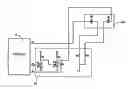
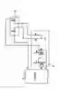
DETAILED DESCRIPTION OF THE INVENTIONReferring to the drawing, a circuit in accordance with a preferred embodiment of the present invention is shown for indicating statuses of a network. The circuit includes a networking chipset 10, a driving circuit 30, and an indicator circuit 40.
The indicator circuit 40 includes a first LED D1 for indicating a type of the network, and a second LED D2 for indicating a data transfer status of the network.
The networking chipset 10 includes a first port 11 for outputting a network type signal, a second port 12 for outputting a linking status signal, and a third port 13 for outputting a data transfer signal.
The driving circuit 30 includes a first transistor Q1, a second transistor Q2, a power supply V, and a number of resistors R1, R2, R3, R4 and R5. The power supply V is provided with a high-level voltage. A base of the first transistor Q1 is coupled to the second port 12. An emitter of the first transistor Q1 is grounded. A collector of the first transistor Q1 is coupled to the power supply V via the resistor R3.
A base of the second transistor Q2 is coupled to a node between the resistor R3 and the collector of the first transistor Q1. An emitter of the second transistor Q2 is coupled to the first port 11. A collector of the second transistor Q2 is coupled to the power supply V via the resistor R2. The resistor R1 is coupled between the emitter and the collector of the second transistor Q2. The collector of the second transistor Q2 is coupled to a negative end of the first LED D1.
A positive end of the first LED D1 is coupled to the power supply V via the resistor R4. A positive end of the second LED D2 is coupled to the power supply V via the resistor R5. A negative end of the first LED D2 is coupled to the third port 13.
When the networking chipset 10 is not linked to a network, the second port 12 outputs a high level linking status signal. The first transistor Q1 conducts. A low level assistant signal is generated on the collector of the first transistor Q1, so the base of the second transistor Q2 is enabled at a low level. The second transistor Q2 is in an off state. The collector of the second transistor Q2 is enabled at a high level. The negative end of the first LED D1 is at a high level, so that the first LED D1 is not on. Simultaneously, no data is transferred by the networking chipset 10, so the third port 13 outputs a high level data transfer signal. Thus, the second LED D2 is not on.
When the networking chipset 10 is connected to a network, the second port 12 outputs a low level linking status signal. The first transistor Q1 is in an off state. A high level assistant signal is generated on the collector of the first transistor Q1, so the base of the second transistor Q2 is enabled at a high level.
If a bandwidth of the network is 10 MB, the first port 11 outputs a high level network type signal. The emitter of the second transistor Q2 is enabled at a high level. The voltage difference between the base and the emitter of the second transistor Q2 is too small to switch on the second transistor Q2. The collector of the second transistor Q2 is enabled at a high level, so the first LED D1 is not on thus indicating connection to the network with 10 MB of bandwidth.
If a bandwidth of the network is 100 MB, the first port 11 outputs a low level network type signal. The emitter of the second transistor Q2 is enabled at a low level. The voltage difference between the base and the emitter of the second transistor Q2 is large enough to switch on the second transistor Q2. The collector of the second transistor Q2 is enabled at a low level, so the first LED D1 conducts and lights to indicate connection to the network with 100 MB of bandwidth.
When the networking chipset 10 is connected to the network, and there is data transferred by the networking chipset 10, the third port 13 outputs a square-wave signal. The second LED D2 is switched between on and off, so the LED D2 flickers to indicate that the networking chipset 10 is transferring date.
It is to be understood, however, that even though numerous characteristics and advantages have been set forth in the foregoing description of preferred embodiments, together with details of the structures and functions of the preferred embodiments, the disclosure is illustrative only, and changes may be made in detail, especially in matters of shape, size, and arrangement of parts within the principles of the invention to the full extent indicated by the broad general meaning of the terms in which the appended claims are expressed.
Claims
What is claimed is:1. A circuit assembly for indicating statuses of a network, comprising:
an indicator circuit comprising a first indicator and a second indicator;
a networking chipset comprising a first port for outputting a network type signal, a second port for outputting a linking status signal, and a third port for outputting a data transfer signal; and
a driving circuit comprising a first transistor, a second transistor, and a power supply capable of powering the first and second indicators, the second indicator connected between the power supply and the third port to indicate data transfer status of the networking chipset, the first port and the second port connected to the first indicator via the first transistor and the second transistor to control the first indicator; a base of the first transistor capable of receiving the linking status signal from the second port, a collector of the first transistor outputting an assistant signal corresponding to the linking status signal, the assistant signal compared with the network type signal received by an emitter of the second transistor for controlling the conduction of the second transistor in order to light or unknot light the second LED to indicate the network's type.
2. The circuit assembly as described in claim 1, wherein the linking status signal indicates whether the networking chipset is connected to the network, and the network type signal indicates the bandwidth of the network.
3. The circuit assembly as described in claim 2, wherein the network type signal is at a high level when the bandwidth of the network is 10 MB, and the network type signal is at a low level when the bandwidth of the network is 100 MB.
4. The circuit assembly as described in claim 1, wherein the first and second indicators are LEDs.
5. The circuit assembly as described in claim 1, wherein a collector of the first transistor is coupled to the power supply via a resistor, and the collector of the second transistor is coupled to the power supply via another resistor.
6. The circuit assembly as described in claim 1, wherein a resistor is connected between the collector and an emitter of the second transistor.
7. A circuit assembly for indicating statuses of a network, comprising:
a networking chipset providing a network type signal definably corresponding to a type of the network;
an indicator definably corresponding to the type of the network; and
a driving circuit comprising a transistor, and a power supply capable of powering the indicator, the indicator electrically connectable in series between the power supply and the transistor;
wherein the transistor receives the network type signal from said networking chipset and an assistant signal, and compares the network type signal with the assistant signal to determine switching on or off the transistor to control the indicator.
8. The circuit assembly as described in claim 7, wherein the network type signal indicates the bandwidth of the network.
9. The circuit assembly as described in claim 8, wherein the network type signal is at a high level when the bandwidth of the network is 10 MB, and the network type signal is at a low level when the bandwidth of the network is 100 MB.
10. The circuit assembly as described in claim 7, further comprising a second indicator capable of accepting a data transfer signal from the networking chipset.
11. The circuit assembly as described in claim 7, further comprising a first transistor, wherein the networking chipset provides a linking status signal, the linking status signal is transferred to the first transistor to generate the assistant signal.
12. The circuit assembly as described in claim 11, wherein the assistant signal is a high-level signal.
13. The circuit assembly as described in claim 11, wherein the linking status signal indicates whether the networking chipset is connected to the network.
14. The circuit assembly as described in claim 11, wherein the networking chipset comprises a first port for outputting the network type signal and a second port for outputting the linking status signal, an emitter of the transistor is coupled to the first port of the networking chipset, a base of the first transistor is coupled to the second port of the networking chipset.
15. The circuit assembly as described in claim 14, wherein the assistant signal is generated on a collector of the first transistor, and transferred to a base of the transistor.
16. A circuit assembly comprising:
a chipset used to generate first signals identifying a current type of connectable networks, and second signals identifying a current status of connective linking to any available network;
an indicator used to indicate said current type of connectable networks;
a first power supply providing a preset voltage;
a second power supply powering said indicator; and
a driving circuit electrically connectable between said chipset, said first power supply and said indicator, said driving circuit accepting said second signals in order to allow passing of said first signals based on said second signals, and said indicator enabling to indicate said current type of connectable networks based on a comparative result of said preset voltage and said passing first signals.
17. The circuit assembly as described in claim 16, wherein said driving circuit comprises two transistors used to accept said second signals to allow said passing of said first signals.
18. The circuit assembly as described in claim 16, wherein said chipset is used to generate third signals transmissible to another indicator in order to indicate a current status of data transfer.
Images & Drawings included:
Sources:
- United States Patent and Trademark Office - verify current appl. status at the USPTO↗
Recent applications in this class:
- » 20250286582 2025-09-11
METHODS AND SYSTEMS FOR IDENTIFYING A FEATURE IN A COMMUNICATION NETWORK - » 20250119177 2025-04-10
MEASUREMENT SYSTEM AND METHOD FOR CHARACTERIZING A MULTI-CORE CABLE - » 20250112667 2025-04-03
Receiver Performance Measurement System and Method Thereof - » 20250070821 2025-02-27
HELICOPTER AUDIO CABLE TEST SYSTEM AND METHOD - » 20240380431 2024-11-14
LOAD CONDITION DETECTION - » 20240348286 2024-10-17
Waveguide component for high frequency testing - » 20240322858 2024-09-26
CONTROL APPARATUS, CONTROL SYSTEM, CONTROL METHOD, AND NON-TRANSITORY COMPUTER READABLE MEDIUM - » 20240235612 2024-07-11
Detection circuit for detecting transmission directionality of transmission line - » 20240088939 2024-03-14
COMMUNICATION DEVICE AND COMMUNICATION METHOD - » 20240080064 2024-03-07
Controller network with break warning features
Recent applications for this Assignee:
- » 20120329427 2012-12-27
Wireless unlocking system - » 20120304477 2012-12-06
Counterbore hole chamfer depth measuring apparatus and method - » 20120276769 2012-11-01
Connector retaining device - » 20120270418 2012-10-25
Printed circuit board used in server - » 20120262041 2012-10-18
Electronic device enclosure - » 20120251746 2012-10-04
Device housing and method for making the same - » 20120236486 2012-09-20
Power supply - » 20120231659 2012-09-13
Connector assembly - » 20120220174 2012-08-30
Cable clamp having a base with a tapered hole and a sleeve with a tapered outer wall to clamp a cable in-between - » 20120194117 2012-08-02
Fan control system