Assembled device of a light module and a liquid crystal panel
US20070103930A1
2007-05-10
11/269,656
2005-11-09
Abstract:
An assembled device of a light module and a liquid crystal panel is composed of a liquid crystal panel whose bottom surface is provided with a light module which includes a circuit board on which are welded at least more than one blue light chip, which is next to a red light chip, as a blue light emitting source, and more than one red light chip as a red light emitting source. A light emitting illumination layer, which is made by uniformly mixing an illumination powder with a transparent glue, is located above the blue light chip and the red light chip, so as to develop into a white light as a back light source whose rendering effect and uniformity are of a good quality and can be easily controlled.
Interested in similar patents?
Get notified when new applications in this technology area are published.
Classification:
H01L2224/73265 » CPC further
Indexing scheme for arrangements for connecting or disconnecting semiconductor or solid-state bodies and methods related thereto as covered by; Means for bonding being of different types provided for in two or more of groups; Location after the connecting process on different surfaces Layer and wire connectors
H01L2924/00014 » CPC further
Indexing scheme for arrangements or methods for connecting or disconnecting semiconductor or solid-state bodies as covered by; Technical content checked by a classifier the subject-matter covered by the group, the symbol of which is combined with the symbol of this group, being disclosed without further technical details
A47F3/00 IPC
Show cases or show cabinets
Description
BACKGROUND OF THE INVENTIONa) Field of the Invention
The present invention relates to an assembled device of a light module and a liquid crystal panel and more particularly to a device wherein a back light source in a white color on the liquid crystal panel is provided with a better light rendering effect.
b) Description of the Prior Art
A typical structure of an assembled device of a liquid crystal panel and a back light source is disclosed in the Taiwan Utility Model Reg. No. M245448, “Light Module of A Liquid Crystal Display,” wherein the light emitting diode used by the light source is composed of an ultraviolet (UV) LED and illumination materials which can emit red, blue, and green light (R, B, G). Its drawback is that the ultraviolet light will create damage to the structure of epoxy resin which is used widely, thereby causing a problem of attenuation to the white light, and enabling a weak brightness to the white light. In particular, the cladding layer of the aforementioned invention is made by mixing illumination powders of red, green, and blue colors. Therefore, another drawback is that the proportions of these three colors and the manufacturing process are difficult to control. Moreover, the claim item 5 of the aforementioned invention discloses that the light emitter diode is a blue light LED, and the illumination powders are red and green light illumination materials. However, it is found that it is difficult to control the proportions of red and green illumination powders and the manufacturing process, so as to hard to control the uniformity of the mixed light (or the white light), thereby causing an inferior light rendering effect to the white light manifested by the liquid crystal panel.
In the Taiwan Utility Model Reg. No. M251143, “Light Device of a Liquid Crystal Screen,” the light source uses a blue light or UV light with the wavelength between 202 nm and 500 nm as a single light source. However, the light source is in short of red light in the spectrum. Therefore, the white light mixed by exciting the illumination board (or the mixed light) is not provided with a good rendering effect and uniformity, and is defined as an impure white light by human eyes.
The Taiwan Utility Model Reg. No. 1228837, “Light Emitting Device,” invented by the present inventor is a white light LED, which uses a blue light and a red light emitting chips (LED) as two light sources. The illumination layer is glued on the blue light chips and the red light chips, and is excited by a light source to emit a green light which is mixed with the blue and red light to form the white light. The invention effectively overcomes the problem of hard to control the proportions of illumination powders of different colors and the manufacturing process as described in the aforementioned invention, and uses the red light LED to replace a conventional red illumination powder, so as to enable the material of illumination layer to be a single color material. This kind of design can solve the problem of hard to control the mixing proportions of different colors and the manufacturing process, and can further control the wavelength of single excited light (i.e., the wavelength of green light). In addition, the invention uses a mixing of the red light emitted from the red light LED, the excited light, and the blue light, to obtain a white light with a better rendering effect. However, the implementation of invention is limited to the new design of white light LED, and there is still no extended implementation applied to the assembled device of a liquid crystal panel and a back light module.
SUMMARY OF THE INVENTIONThe primary object of present invention is to provide an assembled device of a light module and a liquid crystal panel, wherein a white light transmitted from a back light source is provided with a rendering effect and uniformity which are easy to control and are of a good quality.
Another object of the present invention is to provide an assembled device of a light module and a liquid crystal panel, wherein an illumination layer used for the back light module is a light emitting material, such that the wavelength of excited light can be easily controlled, thereby achieving a function of easily controlling the rendering effect and uniformity of the white light from back light source of the liquid crystal panel.
Still another object of the present invention is to provide an assembled device of light module and a liquid crystal panel, wherein the device can be replaced by easily exchanging a light diffusion plate coated with an illumination layer.
To enable a further understanding of the said objectives and the technological methods of the invention herein, the brief description of the drawings below is followed by the detailed description of the preferred embodiments.
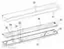
BRIEF DESCRIPTION OF THE DRAWINGSFIG. 1 shows a perspective view upon assembling the present invention.
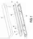
FIG. 2 shows a perspective view upon assembling another implementation of the present invention.
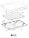
FIG. 3 shows a local cross sectional view of the present invention.
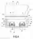
FIG. 4 shows a local cross sectional view of another implementation of the present invention.
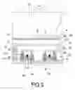
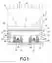
FIG. 5 shows a local cross sectional view of a third implementation of the present invention.
FIG. 6 shows a local cross sectional view of a fourth implementation of the present invention.
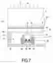
FIG. 7 shows a local cross sectional view of a fifth implementation of the present invention.
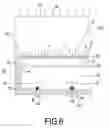
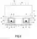
FIG. 8 shows a local cross sectional view of a sixth implementation of the present invention.
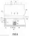
FIG. 9 shows a local cross sectional view of a seventh implementation of the present invention.
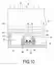
FIG. 10 shows a local cross sectional view of an eight implementation of the present invention.
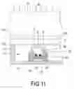
FIG. 11 shows a local cross sectional view of a ninth implementation of the present invention.
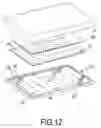
FIG. 12 shows a local cross sectional view of a tenth implementation of the present invention.
DETAILED DESCRIPTION OF THE PREFERRED EMBODIMENTSReferring to FIG. 1, FIG. 2, FIG. 3, FIG. 4, FIG. 5, FIG. 6, FIG. 7, and FIG. 8, the present invention is to provide an assembled device of a light module and a liquid crystal panel comprising a liquid crystal panel 10 whose bottom surface 11 is provided with a light module 20 which includes a circuit board 21 on which are welded at least more than one blue light chip 32 as a blue light B emitting source, and more than one red light chip 34 as a red light R, next to the blue light chip 32, as a red light R emitting source. A light emitting illumination layer 40 is made by uniformly mixing an illumination powder with a transparent glue, and is located on the blue light chip 32 and red light chip 34.
Accordingly, a light diffusion plate 12 is located between the light module 20 and the liquid crystal panel 10, and the illumination layer 40 can be uniformly coated on an upper surface 121 or a lower surface 122 of the light diffusion plate 12. An adhesive layer 124 is located at the lower surface 122 of light diffusion plate 12 for being attached to a frame 211 at a periphery of circuit board 21 (as shown in FIG. 3).
Accordingly, the blue light chip 32 and the red light chip 34 are located in a slot 61 of a same light reflection cap 60 whose pins 62, 64 of two electrodes are welded on the circuit board 21, and the transparent glue 45 is filled in the slot 61.
Accordingly, the blue light chip 32 and the red light chip 34 are located in slots 61 of light reflection caps 60, (60), respectively, and pins 62, 64 of electrodes of the two light reflection caps 60, (60) are welded on the circuit board 21, respectively. A pitch L between the two light reflection caps 60, (60) is controlled to be within 1 mm (as shown in FIG. 5). A transparent glue 45 is filled in the slots 61 of two light reflection caps 60, (60), and on a surface of the circuit board 21.
Accordingly, one or two or three combinations from the following mixtures can be chosen as a material of illumination powder in the illumination layer 40: the aluminum garnet series activated by plutonium and containing Y and Al (YAG:Ce3+), the garnet series activated by europium (YAG:EU2+/3+), and the garnet series activated by terbium (YAG:Tb3+).
Accordingly, a transparent light enhancing membrane 125 or a piece of prism used for enhancing light is added between the liquid crystal panel 10 and the light diffusion plate 12 (as shown in FIG. 12).
Accordingly, the plural and neighboring blue light chips 32 and red light chips 34 are welded on the circuit board 21 in multiple rows of one-dimensional array (as shown in FIG. 2).
Referring to FIG. 1, a liquid crystal panel 10, a light diffusion plate 12, and a light module 20 are in a rectangular shape with a smaller area, which can be applied to a small-scale liquid crystal screen. On the other hand, a liquid crystal panel 10, a light diffusion plate 12, and a light module 20 as shown in FIG. 2 are in a rectangular shape with a larger area, which can be applied to a large-scale liquid crystal screen.
Referring to FIG. 3, a light diffusion plate 12 is a transparent plastic membrane or a thin sheet, whose upper surface 121 is uniformly coated with an illumination layer 40, and whose lower surface 122 is uniformly coated with an adhesive layer 124. A frame 211 is located at a periphery of circuit board 21, and the adhesive layer 124 is attached on the frame 211. In addition, the illumination layer 40 coated on the upper surface 121 of light diffusion plate 12 can be fitted on a bottom surface 11 of a liquid crystal panel 10. Naturally, the illumination layer 40 can be also coated on the upper and lower surfaces 121, 122 of light diffusion plate 12 (not shown in the drawing).
A blue light chip 32 is located in a slot 61 of independent light reflection cap 60, and a red light chip 34 is located in a slot 61 of another independent light reflection cap (60). A pitch L of every neighboring light reflection caps 60, (60) is controlled to be about 1 mm. A transparent glue 45 is sealed in two slots 61, (61) separately, so as to package the blue light chip 32 and the red light chip 34. Pins 62, 64 of positive and negative electrode enable the blue light chip 32 and red light chip 34 to emit a blue light B and a red light R simultaneously, by a function of electrodes. The blue light B and red light R transmits out of the transparent glue 45, the adhesive layer 124, the light diffusion plate 12, the illumination layer 40, and the liquid crystal panel 10, respectively, wherein the blue light B is primarily used to excite the illumination layer 40 to emit an excited light G with a wavelength between 500 nm and 570 nm, which is defined as a green light. The excited light G, the blue light B, and the red light R transmit out of the liquid crystal panel 10 and constitute into a mixed light, which is defined as a white light W. The white light W forms a back light source of the liquid crystal panel 10.
Referring to FIG. 4, an adhesive layer 124 of light diffusion plate 12 can form a square frame to be attached on a frame 211 of circuit board 21, so as to save an area of adhesive layer 121 as shown in FIG. 3.
Referring to FIG. 5, an illumination layer 40 is coated on a lower surface 122 of light diffusion plate 12, and a transparent adhesive layer 124 is coated on a lower surface of illumination layer 40, such that a blue light B and a red light R can transmit from the adhesive layer 124, and the illumination layer 40 can be excited by the blue light B to generate an excited light G. The excited light G, the blue light B, and a red light R transmit out of a liquid crystal panel 10 and constitute into a mixed light, which is defined as a white light W. The white light W serves as a back light source of a liquid crystal screen.
Referring to FIG. 6, a blue light chip 32 and a red light chip 34 are directly welded on a circuit board 21 by pins 62, 64 of positive and negative electrodes, and a transparent glue 45 is filled on a surface of circuit board 21 to completely package the blue light chip 32 and the red light chip 34. An adhesive layer 124 is attached on a surface of transparent glue 45. A blue light B and a red light R emitted from the blue light chip 32 and red light chip 34 transmit out of the transparent glue 45, the adhesive layer 124, a light diffusion plate 12, an illumination layer 40, and a liquid crystal panel 10, wherein the blue light B is used to excite the illumination layer 40 to generate an excited light G. The excited light G and the blue, red lights B, R are mixed to form into a mixed light, which is defined as a white light W.
Referring to FIG. 7, a blue light and a red light chip 32, 34 are installed in a slot 61 of a same light reflection cap 60 and are packaged by a transparent glue 45 at the same time. The blue light and the red light chips 32, 34 emit a blue and a red light B, R which transmit out of the transparent glue 45, a light diffusion plate 12, an illumination layer 40 and a liquid crystal panel 10, wherein the blue light B is primarily used to excite the illumination layer 40 to generate an excited light G to be mixed with the blue and red lights B, R for forming a mixed light (i.e., a white light W), as a back light source of liquid crystal screen.
Referring to FIG. 8, an illumination layer 40 is filled in a slot 61 of light reflection cap 60, to package a blue light chip 32; whereas a transparent glue 45 is filled in a slot 61 of another light reflection cap 60, to package a red light chip 34. A transparent light diffusion plate 12 is located above the light reflection cap 60, such that an excited light G will be generated by exciting the illumination layer 40 with a blue light B, and will transmit out of a light diffusion plate 12 and a liquid crystal panel 10. In addition, a red light R also transmits out of the transparent glue 45, the light diffusion plate 12, and the liquid crystal panel 10, so as to mix the blue, red, and excited lights (B, R, G), thereby forming a mixed light.
Referring to FIG. 9, a blue light chip 32, a red light chip 34, and an illumination layer 40 are installed in a slot 52 and packaged by a bulb-shape transparent glue 45, and a mixed white light W transmits out of a light diffusion plate 12, wherein a main wiring frame 50, and pins of electrodes 56, 55 are welded on a circuit board 21.
Referring to FIG. 10, a blue light chip 32 and a red light chip 34 are installed in a slot 61 of light reflection cap 60, whereas a transparent glue 45 is filled in the slot 61 and packages the blue light chip 32 and the red light chip 34. When the blue and red light chips 32, 34 emit a blue light B and a red light R, the lights will transmit out of the transparent glue 45. A material in light diffusion plate 12 is uniformly mixed into an illuminator which will be excited to an excited light G. Next, a white light W is formed by mixing the excited light G, the blue light B, and the red light R, and transmits out of a liquid crystal panel 10.
Referring to FIG. 11, an illumination layer 40 is filled in a slot 61 of light reflection cap 60 and further packages a blue light chip 32 and a red light chip 34. The blue light chip 32 and the red light chip 34 emit a blue light B and a red light R to excite the illumination layer 40 to generate an excited light G which will mix with the blue light B and the red light R to form a white light W transmitting out of a light diffusion plate 12 and a liquid crystal panel 10.
Referring to FIG. 12, a layer of light enhancing membrane 125 or a piece of prism used for enhancing light can be added on an upper surface 121 of light diffusion plate 12 according to a requirement of designer, which is also an effective implementation of the present invention.
The essential features of present invention lie in that the blue light chip 32 and the red light chip 34, which are mutually independent chips, are used as the back light source of liquid crystal panel 10, and a single color illumination material is further chosen as the illumination layer 10, for example, YAG:Ce3+ or YAG:EU2+/3+ or YAG:Tb3+ of a same color, or a combination of one or two or three kinds of those materials. Accordingly, the problem of considering a proportion of mixing with illumination powders of other different colors does not exist, and the color of light enabled by the illumination layer 40 of a single material is defined as a green light with a wavelength between 500 nm and 570 nm. Therefore, it is easy control the wavelength of excited light G (i.e., defined as the green light) generated when the illumination layer 40 is excited by the blue light B.
The red light chip 34 is a light emitting diode, and the blue light chip 32 is also a light emitting diode. Therefore, by a means of circuit control, the red light chip 34 and the blue light chip can be controlled to emit lights simultaneously, and strength of light emitting can also be controlled, such that the rendering of white light W can be initiated simultaneously.
Referring to FIG. 3, FIG. 4, FIG. 5, FIG. 6, and FIG. 7, when a light diffusion plate 12 and an illumination layer 40 is aging due to a long term interaction of light and electricity, such that a white light W is not provided with a good rendering effect, the entire light diffusion plate 12 containing the illumination layer 40 can be replaced. By an upward force with a human finger, the entire light diffusion plate 12 containing the illumination layer 40 can be torn off the circuit board 21 by a means of its adhesive layer 124, and a new light diffusion plate 12 containing the illumination layer 40 can be attached to the circuit board 21 with its adhesive layer 124, to achieve an object of exchanging with a new product, thereby maintaining a new status of rendering effect of the white light W of liquid crystal panel 10.
It is of course to be understood that the embodiments described herein is merely illustrative of the principles of the invention and that a wide variety of modifications thereto may be effected by persons skilled in the art without departing from the spirit and scope of the invention as set forth in the following claims.
Claims
What is claimed is:1. An assembled device of a light module and a liquid crystal panel comprising a liquid crystal panel whose bottom surface is provided with a light module which includes a circuit board on which are welded at least more than one blue light chip, which is next to a red light chip, as a blue light emitting source, and more than one red light chip as a red light emitting source; a light emitting illumination layer made by uniformly mixing an illumination powder with a transparent glue, and located on the blue light chips and the red light chips.
2. The assembled device of a light module and a liquid crystal panel according to claim 1, wherein a light diffusion plate is located between the light module and the liquid crystal panel, the illumination layer can be uniformly coated on a surface of the light diffusion plate whose lower surface is provided with an adhesive layer for attaching to a frame at a periphery of the circuit board.
3. The assembled device of a light module and a liquid crystal panel according to claim 1, wherein the blue light chip and the red light chip are installed in a slot of a same light reflection cap whose pins of two electrodes are welded on the circuit board and the transparent glue is filled in the slot.
4. The assembled device of a light module and a liquid crystal panel according to claim 1, wherein the blue light chip and the red light chip are independently installed in slots of two separate light reflection caps whose pins of two electrodes are separately welded on the circuit board and whose pitch is controlled to be within 1 mm, and the transparent glue is filled in the slots of two light reflection caps and on the surface of circuit board.
5. The assembled device of a light module and a liquid crystal panel according to claim 1, wherein one or two or three combinations from the following mixtures can be chosen as a material of illumination powder in the illumination layer: the aluminum garnet series activated by plutonium and containing Y and Al (YAG:Ce3+), the garnet series activated by europium (YAG:EU2+/3+), and the garnet series activated by terbium (YAG:Tb3+).
6. The assembled device of a light module and a liquid crystal panel according to claim 1, wherein a transparent light enhancing membrane used for enhancing light is added between the liquid crystal panel and the light diffusion plate.
7. The assembled device of a light module and a liquid crystal panel according to claim 1, wherein the plural and neighboring blue light chips and red light chips are welded on the circuit board in multiple rows of one-dimensional array.
Images & Drawings included:
Sources:
- United States Patent and Trademark Office - verify current appl. status at the USPTO↗
Similar patent applications:
Recent applications in this class:
- » 20250147357 2025-05-08
LIGHT-EMITTING SUBSTRATE AND MANUFACTURING METHOD THEREOF, BACKLIGHT MODULE, AND DISPLAY DEVICE - » 20250138365 2025-05-01
ELECTRONIC DEVICE - » 20250138364 2025-05-01
ILLUMINATION UNIT AND DISPLAY APPARATUS - » 20250138363 2025-05-01
BACKLIGHT PANEL - » 20250130459 2025-04-24
Backlight unit having a rear plate that includes a second bead disposed between a substrate seating unit and a first bead - » 20250102858 2025-03-27
LIGHTING APPARATUS - » 20250102857 2025-03-27
TRANSPARENT DISPLAY - » 20250044646 2025-02-06
LENS UNIT AND A DISPLAY DEVICE INCLUDING THE SAME - » 20250044639 2025-02-06
LIGHT EMITTING DEVICE - » 20250044638 2025-02-06
PLANAR LIGHT SOURCE AND LIQUID CRYSTAL DISPLAY DEVICE