Apparatus for video graphics array testing
US20070109307A1
2007-05-17
11/309,418
2006-08-04
✅ Patent granted
US 7,696,956 B2
2010-04-13
-
-
Bipin Shalwala | Keith Crawley
2028-11-27
Abstract:
An apparatus for video graphics array (VGA) testing includes a connector, a switch, and an output. The connector has at least one signal output pin. The signal output pin of the VGA connector is connected to the output via the switch. The output can be coupled with an oscilloscope or other similar signal analyzing device. It is simple and efficient to use the apparatus for coupling a VGA connector of a computer with an oscilloscope in the VGA testing process.
Inventors:
- TAI-CHEN WANG 12 🇹🇼 Tu-Cheng, Taiwan
- HUANG-NIEN LIN 6 🇹🇼 Tu-Cheng, Taiwan
- Xue-feng Deng 1 🇨🇳 Shenzhen, China
- Hao-yu Guo 1 🇨🇳 Shenzhen, China
Assignee:
- HON HAI PRECISION INDUSTRY CO., LTD. 12,833 🇹🇼 Tu-Cheng, Taiwan
- HON HAI PRECISION INDUSTRY CO., LTD. 2,357 🇹🇼 Tu-Cheng, Taipei Hsien, Taiwan
- Hong Fu Jin Precision Indsutry (ShenZhen) Co., Ltd. 4 🇨🇳 Shenzhen, Guangdong Province, China
Interested in similar patents?
Get notified when new applications in this technology area are published.
Classification:
G09G5/006 » CPC main
Control arrangements or circuits for visual indicators common to cathode-ray tube indicators and other visual indicators; Details of a display terminal, the details relating to the control arrangement of the display terminal and to the interfaces thereto Details of the interface to the display terminal
G09G3/006 » CPC further
Control arrangements or circuits, of interest only in connection with visual indicators other than cathode-ray tubes Electronic inspection or testing of displays and display drivers, e.g. of LED or LCD displays
G06F13/14 IPC
Interconnection of, or transfer of information or other signals between, memories, input/output devices or central processing units Handling requests for interconnection or transfer
G09G1/06 IPC
Control arrangements or circuits, of interest only in connection with cathode-ray tube indicators; General aspects or details, e.g. selection emphasis on particular characters, dashed line or dotted line generation; Preprocessing of data using single beam tubes e.g. three-dimensional or perspective representation, rotation or translation of display pattern, hidden lines, shadows,
G01R31/28 IPC
Arrangements for testing electric properties; Arrangements for locating electric faults; Arrangements for electrical testing characterised by what is being tested not provided for elsewhere Testing of electronic circuits, e.g. by signal tracer
H04N17/00 IPC
Diagnosis, testing or measuring for television systems or their details
Description
FIELD OF THE INVENTIONThe present invention relates to an apparatus for video graphics array (VGA) testing.
DESCRIPTION OF RELATED ARTGenerally, personal computers all use the same type of 15 pin display connector. Because that connector was used in the original IBM Video Graphics Array (VGA) card, it is often referred to simply as the VGA connector. Since the VGA connector is so widely used it acts as a standard that enables different graphic display electronics providers to provide equipment that mate with displays from different display providers.
VGA connectors are widely used among all kinds of video adapters. A generic VGA connector has fifteen pins, twelve of which serve pre-determined functions. For example, the first pin is for transferring red color signals, the third pin is for transferring blue color signals, and the fourteenth pin is for transferring vertical sync signals.
VGA testing is performed to test the quality of VGA signals transmitted by a VGA connector. Performance quality of a VGA card can be ascertained by testing the video information signals transferred by the VGA connector. Conventionally, analysis of the signals is usually done with an oscilloscope. Probes of the oscilloscope are manually touched to each pin of the VGA connector and signal from the pin is then analyzed. It is inconvenient and time consuming to connect with each pin in this way.
What is needed is an apparatus for coupling the VGA connector of a computer with a VGA testing device such as an oscilloscope.
SUMMARY OF THE INVENTIONAn exemplary apparatus for video graphics array (VGA) testing includes a connector, a switch, and an output. The connector has at least one signal output pin. The signal output pin of the VGA connector is connected to the output via the switch. The output can be coupled with an oscilloscope or other similar device suitable for signal analysis.
Other advantages and novel features will become more apparent from the following detailed description when taken in conjunction with the accompanying drawings, in which:
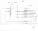
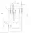
BRIEF DESCRIPTION OF THE DRAWINGSFIG. 1 is a schematic diagram of one embodiment of an apparatus for testing a VGA connector in accordance with a preferred embodiment of the present invention.
DETAILED DESCRIPTION OF THE INVENTIONReferring to FIG. 1, an apparatus 10 includes a VGA connector 12, a switch circuit 14, a first output JP1, and a second output JP2. The VGA connector 12 includes a plurality of signal output pins such as a red signal pin R, a green signal pin G, a blue signal pin B, a vertical sync signal pin VSYNC, and a horizontal sync signal pin HSYNC. The switch circuit includes a plurality of switches S1˜S8.
The red signal pin R is coupled with the first output JP1 and the second output JP2 via the switches S1 and S2 respectively. The green signal pin G is coupled with the first output JP1 and the second output JP2 via the switches S3 and S4 respectively. The blue signal pin B is coupled with the first output JP1 and the second output JP2 via the switches S5 and S6 respectively. The vertical sync signal pin VSYNC is coupled with the first output JP1 via the switch S7. The horizontal sync signal pin HSYNC is coupled with the first output JP1 via the switch S8.
In VGA testing process, the VGA connector 12 is coupled with a computer while the first and second outputs JP1 and JP2 are correspondingly coupled with first and second inputs of an oscilloscope, or other similar device used in the analysis of signals, respectively. The apparatus 10 can selectively transmit signals from the VGA connector 12 to the oscilloscope via the switch circuit 14. The quality of the VGA signals can be ascertained by analysis with the oscilloscope.
It is to be understood, however, that even though numerous characteristics and advantages of the present embodiments have been set forth in the foregoing description, together with details of the structure and function of the invention, the disclosure is illustrative only, and changes may be made in detail, especially in matters of shape, size, and arrangement of parts within the principles of the invention to the full extent indicated by the broad general meaning of the terms in which the appended claims are expressed.
Claims
What is claimed is:1. An apparatus for video graphics array (VGA) testing, comprising:
a VGA connector with a plurality of signal output pins;
a first output and a second output to be coupled with a signal analyzing device; and
a plurality of switches coupling the signal output pins of the VGA connector with the first output and the second output.
2. The apparatus as claimed in claim 1, wherein the output signal pins include a red signal pin, a green signal pin, a blue signal pin, a vertical sync signal pin, and a horizontal sync signal pin.
3. The apparatus as claimed in claim 2, wherein at least one of the red signal pin, the green signal pin, the blue signal pin, the vertical sync signal pin, and the horizontal sync signal pin is coupled with the first output via a corresponding one of the plurality of switches.
4. The apparatus as claimed in claim 3, wherein the red signal pin, the green signal pin, and the blue signal pin are coupled with the second output respectively via corresponding one of the plurality of switches.
5. A connector testing apparatus comprising:
a connector with a plurality of signal output pins;
an output; and
a plurality of switches coupling the signal output pins of the connector with the output.
6. The connector testing apparatus as claimed in claim 5, wherein the output signal pins include a red signal pin, a green signal pin, a blue signal pin, a vertical sync signal pin, and a horizontal sync signal pin.
7. The connector testing apparatus as claimed in claim 6, wherein at least one of the red signal pin, the green signal pin, the blue signal pin, the vertical sync signal pin, and the horizontal sync signal pin is coupled with the output via a corresponding one of the plurality of switches.
Images & Drawings included:
Sources:
- United States Patent and Trademark Office - verify current appl. status at the USPTO↗
Recent applications in this class:
- » 20250259605 2025-08-14
ELECTRONIC DEVICE FOR PROVIDING POWER TO DISPLAY - » 20250246166 2025-07-31
ELECTRONIC DEVICE AND PROCESSING METHOD - » 20250246165 2025-07-31
DISPLAY APPARATUS - » 20250225950 2025-07-10
REMOTE CONTROL OF FUNCTIONAL PARAMETERS AND RENDERING OF OPERATIONAL PREVIEW OF ELECTRONIC DEVICE - » 20250191552 2025-06-12
DISPLAY DEVICES - » 20250174210 2025-05-29
DISPLAY DEVICE INPUT CIRCUIT, DISPLAY DEVICE AND CONTROL METHOD THEREOF - » 20250149008 2025-05-08
METHOD FOR SHORTENING DISPLAY LATENCY BASED ON VARIABLE REFRESH RATE TECHNOLOGY AND RELATED RENDERING DEVICE THEREOF - » 20250118275 2025-04-10
CLIENT-SERVER VISUALIZATION SYSTEM WITH HYBRID DATA PROCESSING - » 20250118274 2025-04-10
DISPLAY SYSTEM AND OPERATION METHOD FOR DISPLAY SYSTEM - » 20250104666 2025-03-27
DISPLAY DEVICE
Recent applications for this Assignee:
- » 20140233961 2014-08-21
Optical communication module including optical-electrical signal converters and optical signal generators - » 20140083669 2014-03-27
HEAT SINK - » 20140063746 2014-03-06
Electronic device with heat dissipation assembly - » 20140061224 2014-03-06
AUTOMATIC VENDING MACHINE - » 20140060914 2014-03-06
Enclosure with shield apparatus - » 20140058727 2014-02-27
MULTIMEDIA RECORDING SYSTEM AND METHOD - » 20140055955 2014-02-27
Fastener - » 20140055322 2014-02-27
DISPLAY SYSTEM AND HEAD-MOUNTED DISPLAY APPARATUS - » 20140054439 2014-02-27
CONTAINER DATA CENTER WITH SUPPORTING APPARATUS - » 20140054311 2014-02-27
AUTOMATIC VENDING MACHINE WITH MOVING MEMBER FOR PRODUCTS