HEAT SINK
US20140083669A1
2014-03-27
13/669,454
2012-11-06
Abstract:
A heat sink includes a bottom plate, a number of first fins extending up from the bottom plate, and a number of second fins. The second fins are detachably connected to tops of the corresponding first fins.
Assignee:
- HON HAI PRECISION INDUSTRY CO., LTD. 12,828 🇹🇼 Tu-Cheng, Taiwan
- HONG FU JIN PRECISION INDUSTRY (SHENZHEN) CO., LTD. 4,225 🇨🇳 Shenzhen City, China
Interested in similar patents?
Get notified when new applications in this technology area are published.
Classification:
H01L21/4882 » CPC main
Processes or apparatus adapted for the manufacture or treatment of semiconductor or solid state devices or of parts thereof; Manufacture or treatment of semiconductor devices or of parts thereof the devices having at least one potential-jump barrier or surface barrier, e.g. PN junction, depletion layer or carrier concentration layer; Manufacture or treatment of parts, e.g. containers, prior to assembly of the devices, using processes not provided for in a single one of the subgroups -; Conductive parts; Bases, plates or heatsinks Assembly of heatsink parts
H01L23/3672 » CPC further
Details of semiconductor or other solid state devices; Arrangements for cooling, heating, ventilating or temperature compensation ; Temperature sensing arrangements; Selection of materials, or shaping, to facilitate cooling or heating, e.g. heatsinks; Cooling facilitated by shape of device Foil-like cooling fins or heat sinks
H01L2924/0002 » CPC further
Indexing scheme for arrangements or methods for connecting or disconnecting semiconductor or solid-state bodies as covered by; Technical content checked by a classifier Not covered by any one of groups , and
H01L2924/00 » CPC further
Indexing scheme for arrangements or methods for connecting or disconnecting semiconductor or solid-state bodies as covered by
F28F3/02 IPC
Plate-like or laminated elements; Assemblies of plate-like or laminated elements Elements or assemblies thereof with means for increasing heat-transfer area, e.g. with fins, with recesses, with corrugations
Description
BACKGROUND
1. Technical Field
The present disclosure relates to a heat sink.
2. Description of Related Art
Heat dissipation for electronic devices in a server, such as central processing units (CPUs), is generally done by heat sinks. Different CPUs have different heat ratings. However, design of the heat sinks is based on the high heat ratings of the CPUs, which is inflexible.
BRIEF DESCRIPTION OF THE DRAWINGS
Many aspects of the present embodiments can be better understood with reference to the following drawings. The components in the drawings are not necessarily drawn to scale, the emphasis instead being placed upon clearly illustrating the principles of the present embodiments. Moreover, in the drawings, all the views are schematic, and like reference numerals designate corresponding parts throughout the several views.
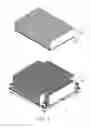
FIG. 1 is an exploded, isometric view of an exemplary embodiment of a heat sink, wherein the heat sink includes a plurality of first fins and a plurality of second fins.
FIG. 2 is an enlarged, inverted view of one of the second fins of FIG. 1.
FIG. 3 is an assembled, isometric view of FIG. 1.
FIG. 4 is an enlarged view of a circled portion IV of FIG. 3.
DETAILED DESCRIPTION
The disclosure, including the accompanying drawings, is illustrated by way of example and not by way of limitation. It should be noted that references to “an” or “one” embodiment in this disclosure are not necessarily to the same embodiment, and such references mean at least one.
FIGS. 1 and 2 show an exemplary embodiment of a heat sink. The heat sink includes a bottom plate 10, a plurality of first fins 20 perpendicularly extending up from the bottom plate 10, and a plurality of second fins 30.
Each second fin 30 includes a main body 31 and a bar 32 connected to a bottom side of the main body 31. A hooking slot 322 is defined in a bottom of the bar 32. A plurality of pairs of resilient tabs 33 extends from a bottom of the bar 32. The resilient tabs 33 of each pair are respectively located at opposite sides of the hooking slot 322. Each resilient tab 33 is substantially C-shaped, arced toward the other resilient tab 33 of the same pair of the resilient tabs 33.
FIGS. 3 and 4 show in assembly, the hooking slot 322 of each second fin 30 is aligned with the corresponding first fin 20 and is manipulated toward the first fin 30. The first fin 20 extends through the pairs of resilient tabs 33 of the second fin 30 and engages in the hooking slot 322, to allow the resilient tabs 33 to resiliently sandwich the first fin 20.
In use, according to the heat rating of the electronic device, a corresponding number of second fins 30 are mounted to the first fins 20. In the embodiment, the second fins 30 are alternately mounted to the first fins 20, for instance, to every other one of the first fins 20.
Even though numerous characteristics and advantages of the embodiments have been set forth in the foregoing description, together with details of the structure and the functions of the embodiments, the disclosure is illustrative only, and changes may be made in details, especially in the matters of shape, size, and arrangement of parts within the principles of the embodiments to the full extent indicated by the broad general meaning of the terms in which the appended claims are expressed.
Claims
What is claimed is:1. A heat sink, comprising:
a bottom plate;
a plurality of first fins extending up from the bottom plate; and
a plurality of second fins detachably connected to tops of corresponding ones of the first fins opposite to the bottom plate.
2. The heat sink of claim 1, wherein a bar is formed on a bottom of each second fin, a hooking slot is defined in a bottom of the bar, the top of the corresponding first fin engages in the hooking slot, a pair of resilient tabs extends from the bottom of the bar, the resilient tabs are located at opposite sides of the hooking slot and resiliently sandwich the corresponding first fin.
3. The heat sink of claim 2, wherein each resilient tab is substantially C-shaped, arced toward the other resilient tab.
4. The heat sink of claim 1, wherein the second fins are alternately mounted to the first fins.
Images & Drawings included:


Sources:
- United States Patent and Trademark Office - verify current appl. status at the USPTO↗
Similar patent applications:
- » 20170271238
Bonded body, power module substrate with heat sink, heat sink, method of manufacturing bonded body, method of manufacturing power module substrate with heat sink, and method of manufacturing heat sink - » 20170271237
Bonded body, power module substrate with heat sink, heat sink, method of manufacturing bonded body, method of manufacturing power module substrate with heat sink, and method of manufacturing heat sink - » 20180108593
Bonded body, substrate for power module with heat sink, heat sink, method for producing bonded body, method for producing substrate for power module with heat sink, and method for producing heat sink - » 20180040535
Bonded body, substrate for power module with heat sink, heat sink, method for producing bonded body, method for producing substrate for power module with heat sink, and method for producing heat sink - » 20180090413
Bonded body, substrate for power module with heat sink, heat sink, method for producing bonded body, method for producing substrate for power module with heat sink, and method for producing heat sink - » 20180068871
Bonded body, substrate for power module with heat sink, heat sink, method for producing bonded body, method for producing substrate for power module with heat sink, and method for producing heat sink - » 20070039726
Fin for a heat sink, heat sink and method for manufacturing a heat sink - » 20110281520
WIRELESS HEAT SINK, WIRELESS HEAT SINK SYSTEM AND WIRELESS HEAT SINKING METHOD FOR THE SAME - » 20140240989
Method of making a heat sink assembly, heat sink assemblies made therefrom, and illumants using the heat sink assembly - » 20110279968
Heat sink having auto switching function, heat sink system and heat sinking method for the same
Recent applications in this class:
- » 20250054775 2025-02-13
INFO PACKAGES INCLUDING THERMAL DISSIPATION BLOCKS - » 20240387195 2024-11-21
CHIP PACKAGE STRUCTURE WITH RING DAM - » 20240371656 2024-11-07
METHOD FOR FORMING SEMICONDUCTOR DEVICE PACKAGE HAVING METAL THERMAL INTERFACE MATERIAL - » 20240304464 2024-09-12
SEMICONDUCTOR PACKAGE AND METHOD OF FABRICATING THE SAME - » 20240203754 2024-06-20
METHOD OF DEPOSITION OF A THERMAL INTERFACE MATERIAL ONTO A CIRCUIT ASSEMBLY AND AN INTEGRATED CIRCUIT FORMED THEREFROM - » 20240021441 2024-01-18
Info packages including thermal dissipation blocks - » 20240014048 2024-01-11
METHOD OF MANUFACTURING SEMICONDUCTOR STRUCTURE HAVING HEAT DISSIPATION STRUCTURE - » 20230411173 2023-12-21
Semiconductor device package having metal thermal interface material - » 20230369068 2023-11-16
CHIP PACKAGE STRUCTURE WITH RING DAM - » 20230369067 2023-11-16
POWER ELECTRONIC SYSTEM AND METHOD FOR FABRICATING A POWER ELECTRONIC SYSTEM
Recent applications for this Assignee:
- » 20140233961 2014-08-21
Optical communication module including optical-electrical signal converters and optical signal generators - » 20140063746 2014-03-06
Electronic device with heat dissipation assembly - » 20140061224 2014-03-06
AUTOMATIC VENDING MACHINE - » 20140060914 2014-03-06
Enclosure with shield apparatus - » 20140058727 2014-02-27
MULTIMEDIA RECORDING SYSTEM AND METHOD - » 20140055955 2014-02-27
Fastener - » 20140055322 2014-02-27
DISPLAY SYSTEM AND HEAD-MOUNTED DISPLAY APPARATUS - » 20140054439 2014-02-27
CONTAINER DATA CENTER WITH SUPPORTING APPARATUS - » 20140054311 2014-02-27
AUTOMATIC VENDING MACHINE WITH MOVING MEMBER FOR PRODUCTS - » 20140049913 2014-02-20
Container data center and heat dissipation system thereof