BACKLIGHT MODULE
US20070109809A1
2007-05-17
11/309,501
2006-08-14
Abstract:
The backlight module includes a casing (21), a light guide plate (26) in the casing (21), a plurality of lamps (23A, 23B, 23C and 23D) arranged to illuminate the light guide plate, a plurality of image sensors (20A, 20B, 20C and 20D) configured for detecting illumination of corresponding lamps, a digital processor (30) configured for processing signals generated by the image sensors, and a plurality of lamp driving loops (32A, 32B, 32C and 32D) configured for receiving feedback signals generated by the digital processor and adjusting a lamp current voltage outputted by a lamp driving loop for each lamp, so as to get an uniform illumination of each lamp.
Assignee:
- HON HAI PRECISION INDUSTRY CO., LTD. 12,828 🇹🇼 Tu-Cheng, Taiwan
Interested in similar patents?
Get notified when new applications in this technology area are published.
Classification:
G02B6/0021 » CPC main
Light guides specially adapted for lighting devices or systems the light guides being planar or of plate-like form; Means for improving the coupling-in of light from the light source into the light guide provided on the surface of the light guide or in the bulk of it by shaping at least a portion of the light guide, e.g. with collimating, focussing or diverging surfaces for housing at least a part of the light source, e.g. by forming holes or recesses
G02B6/0068 » CPC further
Light guides specially adapted for lighting devices or systems the light guides being planar or of plate-like form characterised by the light source being coupled to the light guide Arrangements of plural sources, e.g. multi-colour light sources
G09G3/3406 » CPC further
Control arrangements or circuits, of interest only in connection with visual indicators other than cathode-ray tubes for presentation of an assembly of a number of characters, e.g. a page, by composing the assembly by combination of individual elements arranged in a matrix no fixed position being assigned to or needed to be assigned to the individual characters or partial characters by control of light from an independent source Control of illumination source
H05B41/2824 » CPC further
Circuit arrangements or apparatus for igniting or operating discharge lamps; Circuit arrangements in which the lamp is fed by power derived from dc by means of a converter, e.g. by high-voltage dc using static converters with semiconductor devices by means of a single-switch converter or a parallel push-pull converter in the final stage using control circuits for the switching element
G09G2320/0233 » CPC further
Control of display operating conditions; Improving the quality of display appearance Improving the luminance or brightness uniformity across the screen
G09G2360/145 » CPC further
Aspects of the architecture of display systems; Detecting light within display terminals, e.g. using a single or a plurality of photosensors the light originating from the display screen
F21V7/04 IPC
Reflectors for light sources Optical design
Description
FIELD OF THE INVENTIONThe present invention generally relates to backlight modules, and, particularly, to a backlight module for a liquid crystal display (LCD) device.
DISCUSSION OF THE RELATED ARTMost liquid crystal display (LCD) devices are passive devices in which images are displayed by controlling an amount of light inputted from an external light source. Thus, a separate light source (for example, backlight module) is generally employed for illuminating an LCD panel.
Generally, a backlight module should have good optical illumination and optical uniformity so as to improve the LCD devices' display effect, such as color contrast, optical brightness, and so on.
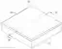
Referring to FIG. 1, a typical backlight module 10 is disposed below a LCD panel 16. The backlight module 10 includes a housing 11, a plurality of lamps 13 disposed in the housing 11 in a parallel manner, a diffusion sheet 14 disposed above the lamps 13, and an optical sheet 15 disposed above the diffusion sheet 14. The housing 11 is a plastic housing, and can also be replaced by a metallic casing. The diffusion sheet 14 is configured for uniformly diffusing the light emitted from the lamps 13, thus, a brightness of the LCD panel 14 would be more uniform. The diffusion sheet 14 is made of transparent resin materials such as polyester (PET) and polycarbonate (PC). The thickness of the diffusion sheet 14 ranges from 0.11 centimeters to 0.15 centimeters. The optical sheet 15 is configured for collimating the emitted light, thereby improving the brightness of light illumination. The optical sheet 15 is also made of transparent resin materials such as polyester (PET) and polycarbonate (PC).
Light emitted from the lamps 13 pass through the diffusion sheet 14 and the optical sheet 15, improving the optical brightness and optical uniformity of the LCD panel 16. However, the lamps are generally not completely identical due to differences developed during manufacturing process. If all of the lamps are driven by the same electric current or voltage, the lamps 13 will illuminate at different variations. Therefore, the optical brightness and optical uniformity of the backlight module 10 will be affected, and accordingly a desired display property of the LCD panel 16 will be reduced.
What is needed, therefore, is a backlight module which can improve the optical brightness and optical uniformity.
SUMMARYThe present invention provides a backlight module. The backlight module includes a casing, a light guide plate disposed in the casing, a plurality of lamps arranged to illuminate the light guide plate, a plurality of image sensors configured for detecting illumination of corresponding lamps, a digital processor configured for processing signals generated by the image sensors, and a plurality of lamp driving loops configured for receiving feedback signals generated by the digital processor and adjusting a lamp current voltage outputted by a lamp driving loop for each lamp, so as to get an uniform illumination of each lamp.
Other advantages and novel features will become more apparent from the following detailed description of preferred embodiments when taken in conjunction with the accompanying drawings.
BRIEF DESCRIPTION OF THE DRAWINGSMany aspects of the backlight module can be better understood with reference to the following drawings. The components in the drawings are not necessarily drawn to scale, the emphasis instead being placed upon clearly illustrating the principles of the backlight module. Moreover, in the drawings, like reference numerals designate corresponding parts throughout the several views.
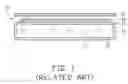
FIG. 1 is a schematic, cross-sectional view of a conventional backlight module;
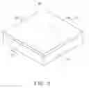
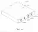
FIG. 2 is a schematic, isometric view of a backlight module according to a first embodiment;
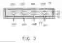
FIG. 3 is a schematic, cross-sectional view taken along the line 111-111 of FIG. 2;
FIG. 4 is a partially isometric view of the backlight module without a casing and reflecting plate of FIG. 2;
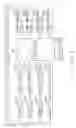
FIG. 5 is a schematic, functional connecting chart of the backlight module of FIG. 2; and
FIG. 6 is a schematic, functional connecting chart of a backlight module according to a second embodiment.
DETAILED DESCRIPTION OF THE EMBODIMENTSReference will now be made to the drawings to describe preferred embodiments of the present backlight module, in detail.
Referring to FIGS. 2 through 4, in a first preferred embodiment, a backlight module 20 includes a casing 21, a light guide plate 26 disposed in the casing 21, a reflecting plate 22, a plurality of lamps 23A, 23B, 23C, and 23D, at least one optical sheet 25, and a plurality of image sensors 20A, 20B, 20C, and 20D. The reflecting plate 22 is disposed between the casing 21 and the light guide plate 26. The lamps 23A, 23B, 23C, and 23D are disposed within the light guide plate 26, for example, the lamps 23A, 23B, 23C, and 23D are disposed in a plurality of receiving hole (not labeled) defined in the light guide plate 26. The receiving hole can also be replaced by a plurality of receiving channel defined in one side of the light guide plate 26. The at least one optical sheet 25 is disposed above the light guide plate 26. The image sensors 20A, 20B, 20C, and 20D are configured for detecting illumination of the corresponding lamps 23A, 23B, 23C, and 23D. The backlight module 20 defines a plurality of through holes 29 below the lamps 23A, 23B, 23C, and 23D; the through holes 29 are configured to run through the reflecting plate 22, the light guide plate 26, and the casing 21. Each of the through hole 29 corresponds to one of the lamps 23A, 23B, 23C, and 23D. The image sensors 20A, 20B, 20C, and 20D are disposed below the casing 21 and aims at the through holes 29 correspondingly.
The lamps 23A, 23B, 23C, and 23D are tubular fluorescent lamps, such as cold cathode fluorescent lamps (CCFLs). The total number of the lamps 23A, 23B, 23C, and 23D are also not limited to this embodiment, and the disposing manner for the lamps 23A, 23B, 23C, and 23D can also be in other manners, such as being disposed in the casing 21.
The optical sheet 25 is selected from one of a diffusing sheet, and a brightness enhancement sheet. The backlight module 20 may also include a plurality of optical sheets 25 according to the actual requirement.
The total number and the disposing manner of the image sensors 20A, 20B, 20C, and 20D corresponds to the total number and the disposing manner of the lamps 23A, 23B, 23C, and 23D so as to detect the illumination of the corresponding lamps 23A, 23B, 23C, and 23D. The image sensors 20A, 20B, 20C, and 20D may also be disposed at any positions in the backlight module 20, and at such positions the image sensors 20A, 20B, 20C, and 20D can effectively detect the illuminations of the lamps 23A, 23B, 23C, and 23D corresponding without interfering with the light emitted from the lamps 23A, 23B, 23C, and 23D. The image sensors 20A, 20B, 20C, and 20D can be selected from a group comprising of a photo diode, a charge couple device, a photoelectric crystal, a photosensitive resistance, and a combination thereof.
Referring to FIG. 5, the backlight module 20 further includes a digital processor 3 electrically connected to the image sensors 20A, 20B, 20C, and 20D, and a plurality of lamp driving loops 32A, 32B, 32C, and 32D electrically connecting with the lamps 23A, 23B, 23C, and 23D respectively. The digital processor 30 is configured for processing signals generated by the image sensors 20A, 20B, 20C, and 20D. The lamp driving loops 32A, 32B, 32C, and 32D are configured for receiving feedback signals generated by the digital processor 30 and adjusting a lamp current or voltage outputted by each driving loop 32A, 32B, 32C, and 32D for each of the lamps 23A, 23B, 23C, and 23D, thus each of the lamps 23A, 23B, 23C, and 23D illuminates uniformly.
When each of the lamps 23A, 23B, 23C, and 23D is driven by the lamp current or voltage outputted by each driving loop 32A, 32B, 32C, and 32D, each of the lamps 23A, 23B, 23C, and 23D are illuminated; each of the image sensors 20A, 20B, 20C, and 20D detects the illumination of each of the lamps 23A, 23B, 23C, and 23D and generates a corresponding signal. The signals generated by the image sensors 20A, 20B, 20C, and 20D are then sent to the digital processor 30. The signals are compared with a required average value, and then the digital processor 30 sends the corresponding feedback signals to the lamp driving loops 32A, 32B, 32C, and 32D. The lamp driving loops 32A, 32B, 32C, and 32D adjust the lamp current or voltage that drives each of the lamps 23A, 23B, 23C and 23D according to the corresponding feedback signals so that each of the lamps 23A, 23B, 23C, and 23D illuminates corresponding to the required average value.
The backlight module 20 further includes an alarm unit 34 connected with the digital processor 30. If one of the image sensors 20A, 20B, 20C, and 20D detects the corresponding illumination and generates a corresponding signal lower than the required average value and such corresponding signal continues over a certain time period, the alarm unit 34 will raise an alarm and further outputs a control signal so that the digital processor 30 cuts off the corresponding signal and the corresponding lamp driving loops 32A, 32B, 32C, and 32D turn off the lamps 23A, 23B, 23C, and 23D correspondingly.
The alarm raised by the backlight module 20 is one of a sound, a flash, and an image. The continuing time of the corresponding signal is selected according to an actual requirement.
Referring to FIG. 6, in a second preferred embodiment, the backlight module (not shown) is substantially the same as the backlight module 20 in the first embodiment. The difference is that the backlight module has a plurality of amplifiers 58A, 58B, 58C, and 58D electrically connecting the image sensors 20A, 20B, 20C, and 20D to the digital processor 30. The amplifiers 58A, 58B, 58C, and 58D are configured for amplifying the signal generated by the image sensors 20A, 20B, 20C, and 20D according to an illumination of the lamps 23A, 23B, 23C and 23D. Therefore, the signal can be more accurately compared with the required average value so that the lamps 23A, 23B, 23C, and 23D can better controlled. The required average value is selected according to an actual requirement.
It is to be understood, however, that even though numerous characteristics and advantages of the present embodiments have been set forth in the foregoing description, together with details of the structures and functions of the embodiments, the disclosure is illustrative only, and changes may be made in detail, especially in matters of shape, size, and arrangement of parts within the principles of the invention to the full extent indicated by the broad general meaning of the terms in which the appended claims are expressed.
Claims
What is claimed is:1. A backlight module, comprising:
a casing;
a light guide plate disposed in the casing;
a plurality of lamps arranged to illuminate the light guide plate;
a plurality of image sensors configured for detecting illumination of corresponding lamps;
a digital processor configured for processing signals generated by the image sensors; and
a plurality of lamp driving loops configured for receiving feedback signals generated by the digital processor and adjusting a lamp current or voltage outputted by a lamp driving loop for each lamp, so as to get an uniform illumination of each lamp.
2. The backlight module according to claim 1, wherein a reflecting plate is disposed between the casing and the light guide plate.
3. The backlight module according to claim 1, wherein the image sensors are disposed at such positions where the image sensors can detect illuminations of the lamps corresponding without interfering with light emitted from the lamps.
4. The backlight module according to claim 1, wherein the lamps are disposed in the light guide plate, the backlight module defines a plurality of through holes below the lamps, the through holes run through the light guide plate and the casing, and each of the through holes corresponds to one of the lamps.
5. The backlight module according to claim 4, wherein each of the image sensors is disposed below the casing and aims at one of the through holes.
6. The backlight module according to claim 1, the backlight module further includes an alarm unit for raising an alarm and outputting a control signal so that the digital processor cuts off the corresponding signal and the corresponding lamp driving loops turn off the lamps correspondingly when one of the image sensors detects the corresponding illumination and generates a corresponding signal lower than a required average value and such corresponding signal continues over a certain time period.
7. The backlight module according to claim 6, wherein the backlight module further includes a plurality of amplifiers connecting the image sensors to the digital processor for amplifying the signal generated by the image sensors according to illumination of the lamps.
8. The backlight module according to claim 7, wherein the alarm raised by the backlight module is one of a sound, a flash and an image.
9. The backlight module according to claim 1, wherein the lamps are cold cathode fluorescent lamps.
10. The backlight module according to claim 1, wherein the image sensors are selected from a group comprising of a photo diode, a charge couple device, a photoelectric crystal, a photosensitive resistance and a combination thereof.
11. A backlight module comprising:
a light guide plate;
a plurality of light sources arranged to illuminate the light guide plate;
a plurality of image sensors positioned corresponding to the light sources and configured for detecting illumination of the corresponding light sources and generating signals associated with the illumination;
a digital processor electrically connected to the image sensors and configured for receiving the signals from the image sensors and generating adjusting signals for adjusting the illumination of the light sources to a predetermined degree; and
a plurality of lamp driving loops electrically connected between the digital processor and the light sources, and configured for adjusting a lamp current or voltage for each lamp in response to the adjusting signals in a manner so as to achieve a predetermined illumination degree of the light guide plate.
12. The backlight module according to claim 11, wherein the lamps are disposed in the light guide plate, the light guide plate defines a plurality of through holes below the lamps, the through holes run through the light guide plate, and each of the through holes corresponds to one of the lamps.
13. The backlight module according to claim 12, wherein each of the image sensors is disposed below the casing and aims at one of the through holes.
14. The backlight module according to claim 11, the backlight module further includes an alarm unit for raising an alarm and outputting a control signal so that the digital processor cuts off the corresponding signal and the corresponding lamp driving loops turn off the lamps correspondingly when one of the image sensors detects the corresponding illumination and generates a corresponding signal lower than a required average value and such corresponding signal continues over a certain time period.
15. The backlight module according to claim 14, wherein the backlight module further includes a plurality of amplifiers electrically connecting the image sensors to the digital processor for amplifying the signal generated by the image sensors according to illumination of the lamps.
16. The backlight module according to claim 15, wherein the alarm raised by the backlight module is one of a sound, a flash and an image.
17. The backlight module according to claim 11, wherein the lamps are cold cathode fluorescent lamps.
18. The backlight module according to claim 11, wherein the image sensors are selected from a group comprising of a photo diode, a charge couple device, a photoelectric crystal, a photosensitive resistance and a combination thereof.
Images & Drawings included:

Sources:
- United States Patent and Trademark Office - verify current appl. status at the USPTO↗
Similar patent applications:
- » 20050162866
Light source portion for backlight module, backlight module using the same, and connection structure of backlight module - » 20140266997
Driving Circuit of Backlight Module, Method for Driving Backlight Module, and LCD Apparatus Incorporated With Such Backlight Module - » 20150362161
LAMPSHADE FOR BACKLIGHT MODULE, BACKLIGHT MODULE AND DISPLAY DEVICE - » 20140133162
Cover for backlight module, backlight module, and liquid crystal display - » 20090201666
Backlight module, backlight module manufacturing method, lighting device, display device and television receiver - » 20130215356
Connecting Piece for Backlight Module, Backlight Module and LCD Device - » 20140160392
OPTICAL FIBER FOR BACKLIGHT MODULE, BACKLIGHT MODULE AND LIQUID CRYSTAL DISPLAY DEVICE - » 20080031007
Housing for backlight module, backlight module and liquid crystal display device - » 20130093991
Backplane of Backlight Module, Backlight Module and LCD Device - » 20170199321
Position-limiting structure for backlight module, backlight module and display device
Recent applications in this class:
- » 20240402409 2024-12-05
RING-SHAPED LIGHT GUIDE MODULE AND LIGHT EMITTING DEVICE - » 20240210609 2024-06-27
LIGHTING FIXTURE WITH WAVEGUIDE - » 20240118476 2024-04-11
Backlight keyswitch and backlight module thereof - » 20240027672 2024-01-25
BACKLIGHT MODULE AND DISPLAY DEVICE - » 20230305212 2023-09-28
Backlight module - » 20230176272 2023-06-08
Light-emitting module and planar light source - » 20230060023 2023-02-23
Light emitting module and planar light source - » 20220252778 2022-08-11
Illumination display panel and method of manufacturing the same - » 20220026620 2022-01-27
Lighting fixture with waveguide - » 20210302644 2021-09-30
Light emitting module
Recent applications for this Assignee:
- » 20140233961 2014-08-21
Optical communication module including optical-electrical signal converters and optical signal generators - » 20140083669 2014-03-27
HEAT SINK - » 20140063746 2014-03-06
Electronic device with heat dissipation assembly - » 20140061224 2014-03-06
AUTOMATIC VENDING MACHINE - » 20140060914 2014-03-06
Enclosure with shield apparatus - » 20140058727 2014-02-27
MULTIMEDIA RECORDING SYSTEM AND METHOD - » 20140055955 2014-02-27
Fastener - » 20140055322 2014-02-27
DISPLAY SYSTEM AND HEAD-MOUNTED DISPLAY APPARATUS - » 20140054439 2014-02-27
CONTAINER DATA CENTER WITH SUPPORTING APPARATUS - » 20140054311 2014-02-27
AUTOMATIC VENDING MACHINE WITH MOVING MEMBER FOR PRODUCTS