Internal combustion engine with dual particulate traps ahead of turbocharger
US20070130946A1
2007-06-14
11/298,882
2005-12-09
Abstract:
An internal combustion engine includes a turbocharger having a turbine, a first set of combustion cylinders, and a second set of combustion cylinders. A first particulate trap is in fluid communication between the first set of combustion cylinders and the turbine. A second particulate trap is in fluid communication between the second set of combustion cylinders and the turbine.
Inventors:
- Richard Edward Winsor 12 🇺🇸 Waterloo, IA, United States
- Kirby Jon Baumgard 4 🇺🇸 Cedar Falls, IA, United States
Interested in similar patents?
Get notified when new applications in this technology area are published.
Classification:
F01N3/021 » CPC main
Exhaust or silencing apparatus having means for purifying, rendering innocuous, or otherwise treating exhaust for cooling, or for removing solid constituents of, exhaust by means of filters
F01N13/011 » CPC further
Exhaust or silencing apparatus characterised by constructional features ; Exhaust or silencing apparatus, or parts thereof, having pertinent characteristics not provided for in, or of interest apart from, groups - , , having two or more purifying devices arranged in parallel
F01N13/107 » CPC further
Exhaust or silencing apparatus characterised by constructional features ; Exhaust or silencing apparatus, or parts thereof, having pertinent characteristics not provided for in, or of interest apart from, groups - , ,; Other arrangements or adaptations of exhaust conduits of exhaust manifolds More than one exhaust manifold or exhaust collector
F02B37/002 » CPC further
Engines characterised by provision of pumps driven at least for part of the time by exhaust using exhaust drives arranged in parallel the exhaust supply to one of the exhaust drives can be interrupted
F02B37/007 » CPC further
Engines characterised by provision of pumps driven at least for part of the time by exhaust with exhaust-driven pumps arranged in parallel, e.g. at least one pump supplying alternatively
F02D41/0007 » CPC further
Electrical control of supply of combustible mixture or its constituents; Controlling intake air for control of turbo-charged or super-charged engines
F02D41/0082 » CPC further
Electrical control of supply of combustible mixture or its constituents; Controlling each cylinder individually per groups or banks
F02D41/029 » CPC further
Electrical control of supply of combustible mixture or its constituents; Circuit arrangements for generating control signals; Introducing corrections for particular conditions exterior to the engine in relation with the state of the exhaust gas treating apparatus to purge or regenerate the exhaust gas treating apparatus the exhaust gas treating apparatus being a particulate filter
F01N13/10 » CPC further
Exhaust or silencing apparatus characterised by constructional features ; Exhaust or silencing apparatus, or parts thereof, having pertinent characteristics not provided for in, or of interest apart from, groups - , ,; Other arrangements or adaptations of exhaust conduits of exhaust manifolds
F01N2340/06 » CPC further
Dimensional characteristics of the exhaust system, e.g. length, diameter or volume of the apparatus; Spatial arrangements of exhaust apparatuses characterised by the arrangement of the exhaust apparatus relative to the turbine of a turbocharger
F01N2430/00 » CPC further
Influencing exhaust purification, e.g. starting of catalytic reaction, filter regeneration, or the like, by controlling engine operating characteristics
F01N2430/02 » CPC further
Influencing exhaust purification, e.g. starting of catalytic reaction, filter regeneration, or the like, by controlling engine operating characteristics by cutting out a part of engine cylinders
F01N2430/06 » CPC further
Influencing exhaust purification, e.g. starting of catalytic reaction, filter regeneration, or the like, by controlling engine operating characteristics by varying fuel-air ratio, e.g. by enriching fuel-air mixture
F02B37/00 » CPC further
Engines characterised by provision of pumps driven at least for part of the time by exhaust
F02D9/06 » CPC further
Controlling engines by throttling air or fuel-and-air induction conduits or exhaust conduits concerning exhaust conduits Exhaust brakes
F02D2009/0279 » CPC further
Controlling engines by throttling air or fuel-and-air induction conduits or exhaust conduits concerning induction conduits; Arrangements; Control features; Details thereof Throttle valve control for intake system with two parallel air flow paths, each controlled by a throttle, e.g. a resilient flap disposed on a throttle
Y02T10/12 » CPC further
Road transport of goods or passengers; Internal combustion engine [ICE] based vehicles Improving ICE efficiencies
Y02T10/12 » CPC further
Road transport of goods or passengers; Internal combustion engine [ICE] based vehicles Improving ICE efficiencies
F01N3/00 IPC
Exhaust or silencing apparatus having means for purifying, rendering innocuous, or otherwise treating exhaust
F02B33/44 IPC
Engines characterised by provision of pumps for charging or scavenging Passages conducting the charge from the pump to the engine inlet, e.g. reservoirs
Description
FIELD OF THE INVENTIONThe present invention relates to internal combustion engines, and, more particularly, to a method and apparatus for filtering particulates from an exhaust stream in such an internal combustion engine.
BACKGROUND OF THE INVENTIONIn order to meet future particulate emission standards for internal combustion (IC) engines, in particular diesel engines, manufacturers of diesel engines are using particulate filters (also referred to as particulate traps). Such particulate traps are typically placed downstream of the turbocharger turbine and remove solid particulate matter before it exits the exhaust system to the ambient environment. After a particulate trap collects particulates for a period of time, increasing the exhaust temperature to a suitable level cleans the trap (also known as regenerating) since the oxygen in the exhaust burns the accumulated carbon in the trap.
Particulate traps for diesel engines are typically relatively large and expensive, and regeneration under light load conditions is problematic because attaining the necessary exhaust temperature is difficult. The use of particulate traps for diesel engines operating under varying load conditions therefore is quite limited.
What is needed in the art is a diesel engine which uses a particulate trap to remove solid particulate matter from the exhaust emissions, with the trap being able to be regenerated under any load conditions on the engine.
SUMMARY OF THE INVENTIONThe invention comprises, in one form thereof, an internal combustion engine including a turbocharger having a turbine, a first set of combustion cylinders, and a second set of combustion cylinders. A first particulate trap is in fluid communication between the first set of combustion cylinders and the turbine. A second particulate trap is in fluid communication between the second set of combustion cylinders and the turbine.
The invention comprises, in another form thereof, a method of operating an internal combustion engine with a plurality of combustion cylinders, including the steps of: filtering particulates from a first set of the combustion cylinders using a first particulate trap in communication between the first set of combustion cylinders and a turbocharger; and filtering particulates from a second set of the combustion cylinders using a second particulate trap in communication between the second set of combustion cylinders and the turbocharger.
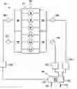
BRIEF DESCRIPTION OF THE DRAWINGSFIG. 1 is a schematic view of an embodiment of an internal combustion engine of the present invention;
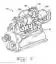
FIG. 2 is a perspective view of the internal combustion engine shown in FIG. 1; and
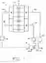
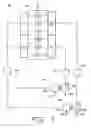
FIG. 3 is a schematic view of another embodiment of an internal combustion engine of the present invention.
DETAILED DESCRIPTION OF THE INVENTIONReferring now to the drawings, there is shown an embodiment of an IC engine 10 of the present invention, which generally includes a block 12 defining a plurality of combustion cylinders 14. In the embodiment shown, IC engine 10 is a diesel engine including six combustion cylinders 14, but may include a different number of combustion cylinders, such as eight, ten, twelve, etc. The plurality of combustion cylinders 14 includes a first set of combustion cylinders 16 which are in communication with an intake manifold 18 and an exhaust manifold 20; and a second set of combustion cylinders 22 in communication with an intake manifold 24 and an exhaust manifold 26.
Located on the upstream side of each intake manifold 18 and 24 is an optional intake throttle 28 and 30, respectively, which may be independently and selectively actuated to control the air flow into first set of combustion cylinders 16 or second set of combustion cylinders 22.
Similarly, optional exhaust brakes 32 and 34 are located on a downstream sides of exhaust manifolds 20 and 26, respectively, and may be independently and selectively actuated to control a flow of exhaust gases therefrom. Intake throttles 28, 30 and exhaust brakes 32, 34 are shown as being selectively actuatable restrictions in the corresponding fluid lines in FIG. 1, but may have a number of different configurations to control fluid flow (i.e., and in turn load) associated with first set of combustion cylinders 16 or second set of combustion cylinders 22.
Exhaust manifolds 20 and 26 each have an exhaust outlet which is in fluid communication with a turbocharger 36 including a turbine 38 which rotatably drives a compressor 40. The spent exhaust gas exits turbine 38 and is exhausted to the ambient environment, as indicated by arrow 42.
Compressor 40 receives combustion air from the ambient environment, as indicated by line 44, and provides compressed combustion air to intake manifolds 18 and 24. The compressed combustion air is heated as a result of the work during the compression operation, and is cooled by an aftercooler 46 located downstream from compressor 40.
According to an aspect of the present invention, a first particulate trap 48 is in fluid communication between first set of combustion cylinders 16 and turbine 38, and a second particulate trap 50 is in fluid communication between second set of combustion cylinders 22 and turbine 38. Each particulate trap 48 and 50 filters particulates from the exhaust streams which are exhausted from exhaust manifolds 20 and 26, respectively.
During operation of IC engine 10, first particulate trap 48 filters particulates from first set of combustion cylinders 16, and second particulate trap 50 filters particulates from second set of combustion cylinders 22. In the event it is necessary to regenerate (i.e., clean) first particulate trap 48 and/or second particulate trap 50, it is desirable to control the fuel flow rate as well as the combustion air flow rate to first set of combustion cylinders 16 or second set of combustion cylinders 22 in a manner that increases the temperature and oxygen within first particulate trap 48 or second particulate trap 50.
More particularly, to regenerate first particulate trap 48, it is possible to increase the fuel rate to first set of combustion cylinders 16 and decrease the fuel rate to second set of combustion cylinders 22. This provides a temperature and oxygen concentration within first particulate trap 48 which is sufficient to burn the accumulated carbon within first particulate trap 48. It is also possible to apply exhaust brake 34 or intake throttle 30 to the non-regenerating second set of combustion cylinders 22, which causes the load to increase on the regenerating first set of combustion cylinders 16, thereby increasing the exhaust temperature within first particulate trap 48. In this manner, regeneration of first particulate trap 48 can occur under virtually any load condition.
Conversely, to regenerate second particulate trap 50, it is possible to increase a fuel rate to second set of combustion cylinders 22 and decrease a fuel rate to first set of combustion cylinders 16, thereby regenerating second particulate trap 50. Intake throttle 28 and exhaust brake 32 can similarly be applied to the non-regenerating first set of combustion cylinders 16, which causes the load to increase on the regenerating second set of combustion cylinders 22, thereby increasing the exhaust temperature within second particulate trap 50 for burning the accumulated carbon therein.
Referring now to FIG. 3, there is shown another embodiment of an IC engine 60 of the present invention. IC engine 60 is similar in many respects to IC engine 10 shown in FIGS. 1 and 2, as indicated by the majority of the corresponding reference numbers. In contrast with the embodiment of IC engine 10 shown in FIG. 1, however, each particulate trap 48 and 50 is coupled in parallel with a corresponding turbocharger 36 and 62, respectively. Turbocharger 62 includes a turbine 64 which rotatably drives a compressor 66. The spent exhaust gas from exhaust manifold 26 exits turbine 64 and is exhausted to the ambient environment, as indicated by arrow 68. Compressor 66 receives combustion air from the ambient environment, as indicated by line 70.
In the embodiment of IC engine 10 shown in FIG. 1, optional and controllable flow restrictions 28, 30, 32 and 34 are used to exert an additional load on the set of combustion cylinders associated with the non-regenerating particulate trap 48 or 50, to assist in the regeneration of the regenerating particulate trap 48 or 50. IC engine 60 shown in FIG. 3 does not include controllable flow restrictions, but instead includes two variable geometry turbochargers 36 and 62 which may be controllably actuated in a manner to exert an additional load on the set of combustion cylinders associated with the non-regenerating particulate trap 48 or 50. In the embodiment shown in FIG. 1, turbocharger 36 is configured as a fixed geometry turbocharger, and in the embodiment shown in FIG. 3, turbochargers 36 and 62 are each configured as a variable geometry turbocharger (VGT), as indicated by the diagonal arrows through turbines 38 and 64, respectively. Depending upon which particulate trap 48 or 50 is being regenerated, the vanes in the turbine of the other turbocharger may be actuated to provide a flow restriction and thereby increase the load on the set of combustion cylinders associated with the regenerating particulate trap 48 or 50.
Having described the preferred embodiment, it will become apparent that various modifications can be made without departing from the scope of the invention as defined in the accompanying claims.
Claims
1. An internal combustion engine, comprising:
a turbocharger including a turbine;
a first set of combustion cylinders;
a first particulate trap in fluid communication between said first set of combustion cylinders and said turbine;
a second set of combustion cylinders; and
a second particulate trap in fluid communication between said second set of combustion cylinders and said turbine.
2. The internal combustion engine of claim 1, wherein said first set of combustion cylinders includes at least 2 cylinders, and said second set of combustion cylinders includes at least 2 cylinders.
3. The internal combustion engine of claim 1, further including an exhaust brake in communication with said first set of combustion cylinders and said second set of combustion cylinders.
4. The internal combustion engine of claim 1, further including an intake throttle in communication with said first set of combustion cylinders and said second set of combustion cylinders.
5. The internal combustion engine of claim 1, wherein said internal combustion engine comprises a diesel engine.
6. A method of operating an internal combustion engine including a plurality of combustion cylinders, comprising the steps of:
filtering particulates from a first set of the combustion cylinders using a first particulate trap in communication between the first set of combustion cylinders and a turbocharger; and
filtering particulates from a second set of the combustion cylinders using a second particulate trap in communication between the second set of combustion cylinders and said turbocharger.
7. The method of operating an internal combustion engine of claim 6, including the step of regenerating said first particulate trap and said second particulate trap independently from each other.
8. The method of operating an internal combustion engine of claim 7, including the step of increasing a fuel rate to said first set of combustion cylinders and decreasing a fuel rate to said second set of combustion cylinders, thereby regenerating said first particulate trap.
9. The method of operating an internal combustion engine of claim 8, including the step of applying an exhaust brake to said second set of combustion cylinders.
10. The method of operating an internal combustion engine of claim 8, including the step of applying an intake throttle to said second set of combustion cylinders.
11. The method of operating an internal combustion engine of claim 7, including the step of increasing a fuel rate to said second set of combustion cylinders and decreasing a fuel rate to said first set of combustion cylinders, thereby regenerating said second particulate trap.
12. The method of operating an internal combustion engine of claim 11, including the step of applying an exhaust brake to said first set of combustion cylinders.
13. The method of operating an internal combustion engine of claim 11, including the step of applying an intake throttle to said first set of combustion cylinders.
14. The method of operating an internal combustion engine of claim 6, wherein said internal combustion engine comprises a diesel engine.
15. An internal combustion engine, comprising:
a first set of combustion cylinders and a second set of combustion cylinders;
a first variable geometry turbocharger and a second variable geometry turbocharger;
a first particulate trap in fluid communication between said first set of combustion cylinders and said first variable geometry turbocharger; and
a second particulate trap in fluid communication between said second set of combustion cylinders and said second variable geometry turbocharger.
16. The internal combustion engine of claim 15, wherein each of said first variable geometry turbocharger and said second variable geometry turbocharger include a variable geometry turbine.
Images & Drawings included:
Sources:
- United States Patent and Trademark Office - verify current appl. status at the USPTO↗
Similar patent applications:
Recent applications in this class:
- » 20230160326 2023-05-25
Method and apparatus to enhance fractional efficiency of diesel and gasoline particulate filters - » 20220356824 2022-11-10
System and method for filtering exhaust gases of a vehicle - » 20220082039 2022-03-17
Detection device, detection method, and exhaust purification device with detection device - » 20210381413 2021-12-09
Particulate filter - » 20210310388 2021-10-07
Smokeless exhaust tube - » 20210270159 2021-09-02
Carbon capture in an internal combustion engine - » 20210047951 2021-02-18
Engine muffler apparatus - » 20200378284 2020-12-03
Work machine provided with engine - » 20200370452 2020-11-26
Gasoline particulate filters with high initial filtering efficiency and methods of making same - » 20200355102 2020-11-12
Method and system for gasoline particulate filter