Sales slip printer with a tray arrangement for continuous paper segments
US20070131072A1
2007-06-14
11/605,511
2006-11-28
✅ Patent granted
US 7,565,855 B2
2009-07-28
-
-
Kenneth E. Peterson | Sean Michalski
2027-09-05
Abstract:
A sales slip printer for segments (26) that are to be separated from a continuous paper strip (14) with a V-shaped knife (18) and a stacking tray (24) for the segments (26) separated from the continuous paper strip (14) located behind an output channel (12), which is separated from the output channel (12) by projections (28) extending in the side edge areas of the output channel (12), and a slide (30), which pushes through the already separated edges of the continuous paper strip (14) into the stacking tray (24) between the projections (28) during a cutting action.
Inventors:
- Andreas Jeschke 3 🇩🇪 Dallgow, Germany
- Wolfgang Malke 8 🇩🇪 Berlin, Germany
- Wilfried Dobring 1 🇩🇪 Berlin, Germany
Assignee:
- Wincor Nixdorf International GmbH 126 🇩🇪 , Germany
Interested in similar patents?
Get notified when new applications in this technology area are published.
Classification:
B26D1/085 » CPC further
Cutting through work characterised by the nature or movement of the cutting member or particular materials not otherwise provided for ; Apparatus or machines therefor; Cutting members therefor involving a cutting member which does not travel with the work having a linearly-movable cutting member wherein the cutting member reciprocates of the guillotine type for thin material, e.g. for sheets, strips or the like
B41J13/106 » CPC further
Devices or arrangements specially adapted for supporting or handling copy material in short lengths, e.g. sheets; Sheet holders, retainers, movable guides , or stationary guides for the sheet output section
G07B5/02 » CPC further
Details of, or auxiliary devices for, ticket-issuing machines for cutting-off or separating tickets
B26D1/0006 » CPC further
Cutting through work characterised by the nature or movement of the cutting member or particular materials not otherwise provided for ; Apparatus or machines therefor; Cutting members therefor Cutting members therefor
B26D2001/004 » CPC further
Cutting through work characterised by the nature or movement of the cutting member or particular materials not otherwise provided for ; Apparatus or machines therefor; Cutting members therefor; Cutting members therefor not rotating
B26D2001/006 » CPC further
Cutting through work characterised by the nature or movement of the cutting member or particular materials not otherwise provided for ; Apparatus or machines therefor; Cutting members therefor; Cutting members therefor the cutting blade having a special shape, e.g. a special outline, serrations
Y10T83/2022 » CPC further
Cutting; With product handling means Initiated by means responsive to product or work
Y10T83/2037 » CPC further
Cutting; With product handling means; Including means to form or hold pile of product pieces In stacked or packed relation
Y10T83/2148 » CPC further
Cutting; With product handling means; Means to move, guide, or permit free fall or flight of product; Means to move product out of contact with tool; Moving stripper timed with tool stroke Linkage actuated
Y10T83/2179 » CPC further
Cutting; With product handling means; Means to move, guide, or permit free fall or flight of product Including means to move, or resist movement of, cut pieces along delivery chute
Y10T83/2218 » CPC further
Cutting; With product handling means; Means to move, guide, or permit free fall or flight of product; Guide Abutment interposed in path of free fall or flight of product
Y10T83/869 » CPC further
Cutting Means to drive or to guide tool
Y10T83/8841 » CPC further
Cutting; Means to drive or to guide tool; With simple rectilinear reciprocating motion only Tool driver movable relative to tool support
Y10T83/8854 » CPC further
Cutting; Means to drive or to guide tool; With simple rectilinear reciprocating motion only Progressively cutting
Y10T83/9447 » CPC further
Cutting; Tool or tool with support; Cutting couple type Shear type
B26D1/06 IPC
Cutting through work characterised by the nature or movement of the cutting member or particular materials not otherwise provided for ; Apparatus or machines therefor; Cutting members therefor involving a cutting member which does not travel with the work having a linearly-movable cutting member wherein the cutting member reciprocates
B26D5/08 » CPC further
Arrangements for operating and controlling machines or devices for cutting, cutting-out, stamping-out, punching, perforating, or severing by means other than cutting Means for actuating the cutting member to effect the cut
B41J11/70 » CPC main
Devices or arrangements of selective printing mechanisms, e.g. ink-jet printers, thermal printers, for supporting or handling copy material in sheet or web form; Applications of cutting devices cutting perpendicular to the direction of paper feed
B65H35/06 » CPC further
Delivering articles from cutting or line-perforating machines; Article or web delivery apparatus incorporating cutting or line-perforating devices, e.g. adhesive tape dispensers from or with transverse cutters or perforators from or with blade, e.g. shear-blade, cutters or perforators
B26D7/32 IPC
Details of apparatus for cutting, cutting-out, stamping-out, punching, perforating, or severing by means other than cutting; Means for performing other operations combined with cutting for conveying or stacking cut product
Description
BACKGROUND OF THE INVENTION1. Technical Field
The invention relates to a sales slip printer with a stacking device for segments separated from a continuous paper strip.
2. Discussion
Printers with a cutting apparatus and an output channel for segments separated from a continuous paper are already known, wherein the cutting apparatus initially cuts and then abscises the continuous paper from the side edges, whereby a movable knife that is perpendicular to the surface of the continuous paper strip and having a V-formed blade is provided on the one side of the continuous paper strip and an opposing blade edge on the other side of the continuous paper strip.
These printers have the problem that a separated segment remains in the output channel after the cutting action, which is pushed out of the output channel by a subsequent segment and falls to the floor.
In DE 34 45 744 C1 it has therefore been described to not completely cut through a paper strip, so that the individual segments are held together through a web. In this manner, unaesthetic paper streamers accrue on the work space. Incidentally, the provision of a movable knife that is perpendicular to the surface of the continuous paper strip and with a V-formed blade on the one side of the continuous paper strip and the provision of an opposing blade edge on the other side of the continuous paper strip is known from DE 34 45 744 C1.
SUMMARY OF THE INVENTIONIt is the object of the invention to improve a printer of the described type, such that individual segments of the continuous paper are fed out of the output channel and are stacked in the sequence of their emergence.
In accordance with the invention, a stacking tray located behind the output channel gathers the segments separated from the continuous paper strip, such that the latter in the sequence of their emergence are gathered. For this purpose, the stacking tray is separated by extending projections in the side edge areas of the output channel. Furthermore, a slide is provided, which pushes through the already separated edges of the continuous paper strip between the projections into the stacking tray during a cutting action and thereby enable a stack of the segments.
In accordance with a preferred embodiment of the invention, the slide is moved concurrently with the knife, wherein the slide has a larger gap to the continuous paper strip than the knife at the beginning of the cutting action and overtakes this with progressive feeding of the knife. In this manner it is achieved that the edges of the continuous paper strip are already incised when the slide engages the continuous paper strip. With further feeding of the knife and the slide, the continuous paper strip is further cut into its center. Concurrently, the slide pushes through the already separated edges of the continuous paper strip between the projections until they arrive behind the projections. Through this, a deviation of the continuous paper strip is inhibited and it can be deposited standing upright in the stacking tray. As soon as the continuous paper strip is completely cut through, the segment arrives in the stacking tray. Subsequent segments proceed in the same manner, such that a subsequent segment is deposited behind the first segment.
Commensurate with a preferred further embodiment of the invention, the knife and the slide are moved using a common drive. Preferably, the slide is thereby coupled with the knife by a translation drive.
Preferably, the translation drive is realized through a pivotable lever, to which the knife and the slide are jointed, wherein the length of a first lever arm associated with the slide is larger than the length of a second lever arm associated with the knife. With pivoting of the lever, the slide travels along a larger path than the knife. The lever design is particularly simple and thereby inexpensive to construct.
BRIEF DESCRIPTION OF THE DRAWINGSFurther features and advantages of the invention arise from the following description, which describes an exemplary embodiment of the invention in conjunction with the attached figures. It is shown in:
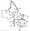
FIG. 1 is a perspective side view of the basic components of a printer in accordance with the invention,
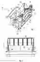
FIG. 2 is a front view of the printer of FIG. 1,
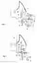
FIG. 3 is a schematic side view, the knife and the slide of the printer of FIG. 1 in their rest position, and
FIG. 4 is a schematic side view, the knife and the slide of the printer of FIG. 1 in their actuated end position.
DESCRIPTION OF THE PREFERRED EMBODIMENTSIn FIG. 1 the basic components of a printer 10 in accordance with the invention are illustrated in a perspective side view. An output channel 12 leads upward from a printer station, not shown in FIG. 1, which is located underneath the illustrated components. A continuous paper strip 14 lies in the output channel 12. A cutting apparatus 16 is located in the output channel 12. This includes a movable knife 18 that is perpendicular to the surface of the continuous paper strip 14 and that includes a V-formed blade, which is known from DE 34 45 744 C1, on the front side of the continuous paper strip 14 and a cutting beam 20 with an opposing cutting edge 22 (FIG. 3) on the other side of the continuous paper strip 14.
Behind the output channel 12 is located a stacking tray 24 for the sections 26 (FIG. 4) separated from the continuous paper strip 14, and which is separated from the output channel 12 by extending projections 28 in the side edge area of the output channel 12. Above the knife and parallel thereto is located a slide 30, which is shoe-formed in at least the side cross-section and which has a V-form corresponding to the knife 18.
A shaft 32 is rotatably supported on the printer 10 below the knife 18 and parallel thereto. A lever is rotatably fixed to the shaft 32 at both sides of the printer 10. The knife 18 and the slide 30 are jointed to these, wherein the length of a first lever arm 38 associated with the slide 30 is larger than the length of a second lever arm 40 associated with the knife 18.
FIG. 2 shows the printer 10 in a front view. A back wall 42 of the stacking tray 24 is recognizable behind the section 26. The bottom ends 44 of the projections 28 extend into the output channel 12, such that its clearance width B in the area of the projections 28 is smaller than the width of the section 26. The gap between the projections 28 widen in a transport apparatus T of the section 26 until achieving the width of the stacking tray 24.
The function of the stacking apparatus will be explained in the following in hand with FIGS. 3 and 4, wherein FIG. 3 shows the knife 18 and the slide 30 in their rest position and FIG. 4 in their actuated end position.
In the rest position of the knife 18 and the slide 30 (FIG. 3), the continuous paper strip 14 is located in the output channel 12 and in front of the stacking tray 24. In this position, the slide 30 has a larger gap to the continuous paper strip 14 than the knife 18. The shaft 32 is rotated in the direction of the arrow 36 for cutting of a section from the continuous paper strip 14, whereby the lever 34 pivots in the direction of the stacking tray 24. Through further pivoting of the lever 34, initially the side areas of the knife 18 come into contact with the continuous paper strip 14 and these begin to cut.
When the side incisions are so deep that the uncut part of the continuous paper strip 14 has at most the width of the clearance width B between the projections 28, the slide 30 comes into contact with the continuous paper strip 14 and pushes this through between the projections. The already cut areas of the continuous paper strip are initially held back by the projections 28 and are bent against the feed direction of the slide 30. With further feeding of the knife 18 and the slide 30, the already cut areas of the continuous strip 14 spring through between the projections 28 and again stretch as a result of the of the elasticity of the paper.
Also when the continuous paper strip 14 is completely cut through, the pivoting movement of the lever 34 is still continued about a couple of angular degrees until the slide 30 reaches the end position illustrated in FIG. 4. In this manner, the section 26 is pushed against the back wall 42 of the stacking tray 24. Should further sections 26 be separated from the continuous paper strip 14, these are deposited on top of the previous section. The first section can not be pushed out of the stacking tray 24, because the second section does not come into contact with the first deposited continuous paper section during the feeding of the second continuous paper section 26. The sections 26 are stacked in the stacking tray one after the other.
Claims
What is claimed is:1. A sales slip printer with a cutting apparatus (16) and an output channel (12) for segments (26) separated from a continuous paper strip (14), wherein the cutting apparatus (16) initially cuts and then abscises the continuous paper from the side edges, whereby a movable knife that is perpendicular to the surface of the continuous paper strip and with a V-formed blade is provided on the one side of the continuous paper strip and an opposing blade edge on the other side of the continuous paper strip, characterized by
a stacking tray (24) located behind the output channel (12) for the segments (26) separated from the continuous paper strip (14), which is separated from the output channel (12) by projections (28) extending in the side edge areas of the output channel (12), and a slide (30), by means of which the segment (26) of the continuous paper strip (14) is already pushed through between the projections (28) during a cutting action.
2. A sales slip printer in accordance with claim 1, characterized in that the slide (30) is concurrently movable with the knife (18), wherein it has a larger gap to the continuous paper strip (14) than the knife (18) at the beginning of the cutting action and overtakes this with progressive feeding of the knife (18).
3. A sales slip printer in accordance with claim 1, characterized in that the slide (30) conforms to the V-form of the blade.
4. A sales slip printer in accordance with claim 1, characterized in that the knife (18) and the slide (30) are commonly drivable.
5. A sales slip printer in accordance with claim 4, characterized in that the slide (30) is coupled with the knife (18) by a translation drive.
6. A sales slip in accordance with claim 5, characterized in that the knife (18) and the slide (30) are jointed to a pivotable lever (34), wherein the length of a first lever arm (38) associated with the slide (30) is larger than the length of a second lever arm (40) associated with the knife (18).
7. A sales slip printer comprising:
a cutting apparatus and an output channel for segments separated from a continuous paper strip wherein the cutting apparatus initially cuts and then abscises the continuous paper from the side edges,
a movable knife that is perpendicular to the surface of the continuous paper strip and with a V-formed blade is provided on the one side of the continuous paper strip and an opposing blade edge on the other side of the continuous paper strip,
a stacking tray located behind the output channel for the segments separated from the continuous paper strip which is separated from the output channel by projections extending in the side edge areas of the output channel; and
a slide by means of which the segment of the continuous paper strip is already pushed through between the projections during a cutting action.
8. A sales slip printer in accordance with claim 7 wherein the slide is concurrently movable with the knife wherein it has a larger gap to the continuous paper strip than the knife at the beginning of the cutting action and overtakes this with progressive feeding of the knife
9. A sales slip printer in accordance with claim 7 wherein the slide conforms to the V-form of the blade.
10. A sales slip printer in accordance with claim 7 wherein the knife and the slide are driven in common.
11. A sales slip printer in accordance with claim 10 wherein the slide is coupled with the knife by a translation drive.
12. A sales slip in accordance with claim 11 wherein the knife and the slide are jointed to a pivotable lever, wherein the length of a first lever arm associated with the slide is larger than the length of a second lever arm associated with the knife.
Images & Drawings included:
Sources:
- United States Patent and Trademark Office - verify current appl. status at the USPTO↗
Recent applications in this class:
- » 20250289247 2025-09-18
Cutter Integrated with Tamping Mechanism for Enhanced Linerless Processing - » 20250289246 2025-09-18
PRINTER AND CUTTING UNIT - » 20250178364 2025-06-05
PRINTER AND CUTTER UNIT OF PRINTER - » 20250074084 2025-03-06
PRINTER AND CUTTER UNIT - » 20250033383 2025-01-30
IMAGE RECORDING APPARATUS - » 20240399772 2024-12-05
PRINTING DEVICE AND CUTTING DEVICE - » 20240375418 2024-11-14
PRINTER - » 20240375417 2024-11-14
PRINTER AND CUTTER UNIT - » 20240326478 2024-10-03
Cutter unit and printer with cutter unit - » 20240239117 2024-07-18
Flatbed Printer with Integrated Creasing and Cutting
Recent applications for this Assignee:
- » 20180108223 2018-04-19
Determination of filling levels at the checkout terminal - » 20170069176 2017-03-09
Card reading device and so-equipped self-service terminal and method for monitoring the same - » 20160203664 2016-07-14
Coin separating device - » 20160005254 2016-01-07
Cash box having a movable base tray - » 20150371474 2015-12-24
Device for sorting coins - » 20150371473 2015-12-24
Coin separation device - » 20150251861 2015-09-10
Cash cassette comprising a press-on unit having an elastic snap-in element - » 20150248803 2015-09-03
Cash box having an adjustable belt support - » 20150248802 2015-09-03
Cash box with two locking units - » 20150247354 2015-09-03
Cash box with a height limiter engaging with the retaining element