Swivel ball bearing
US20070134056A1
2007-06-14
11/635,727
2006-12-08
✅ Patent granted
US 7,455,470 B2
2008-11-25
-
-
Michael P Ferguson
2026-12-08
Abstract:
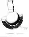
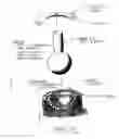
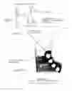
A swivel bearing assembly is presented (Drawing #1). This swivel bearing assembly (Drawing #2) consists of an outer housing (Part #1) ball and shaft (Part #2), cover (Part #3) and ball bearings (Part #4).
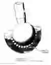
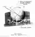
The main feature of this design is the “free zone” channel (Drawing #3). The “free zone” channel allows the ball bearings (Part #4) to roll freely in the assembly, as they follow the motion of the ball and shaft.
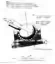
The ball bearings incorporated in this design eliminate friction between ball and outer housing. Ball and shaft can have simultaneous rotational and angular motion. Only unidirectional load can be applied to this bearing—in the direction of the mounting surface (Drawing #5).
Interested in similar patents?
Get notified when new applications in this technology area are published.
Classification:
F16C11/0619 » CPC main
Pivots; Pivotal connections; Pivotal connections; Ball-joints; Other joints having more than one degree of angular freedom, i.e. universal joints the female part comprising a blind socket receiving the male part
Y10T403/32631 » CPC further
Joints and connections; Articulated members; Pivoted Universal ball and socket
Y10T403/32737 » CPC further
Joints and connections; Articulated members; Pivoted; Universal ball and socket including liner, shim, or discrete seat
F16C11/00 IPC
Pivots; Pivotal connections
F16C11/06 IPC
Pivots; Pivotal connections; Pivotal connections Ball-joints; Other joints having more than one degree of angular freedom, i.e. universal joints
Description
PRIOR ARTMost prior-art swivel bearings (ball joints) do not utilize ball bearings as a friction-reducing medium.
Rubbing surfaces of prior-art ball joint designs generally consist of metal on metal, metal on plastic, or plastic on plastic, with considerable friction between rubbing surfaces; therefore, life and load capability are considerably diminished. Prior-art swivel bearing (Drawing #6) utilizes a small number of ball bearings supporting the ball. Any force directed toward the mounting surface and not directed toward the ball bearings supporting it will cause the ball to lose contact with the ball bearings supporting it, resulting in failure of the device.
In the design herein presented, the ball and shaft are always supported by the ball bearings, regardless of the load direction towards the mounting surface (Drawing #5).
DETAILED DESCRIPTIONA bearing (ball joint) with ball bearings (Drawing #1 and #1A) is presented. The main feature of this design is a “free zone” channel (shown enlarged in Drawing #3, FIG. 1 and FIG. 2). The cross-section of the “free zone” channel is larger than the diameter of the ball bearings in order to accommodate their free movement in the channel. The ball bearings can flow into and out of the “free-zone” channel during angular displacement of the ball and shaft (Drawing #5).
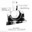
During rotational motion of the ball and shaft (Drawing #4), the ball bearings (Part #4) mimic the motion of prior-art radial bearings. It is essential that each swivel bearing assembly have less than a full complement of ball bearings (Part #4). A full complement of ball bearings (Part #4) would impede the balls' free movement and cause that ball bearing assembly to jam.
For optimum function of the swivel bearing, the correct number of ball bearings for each bearing assembly must be determined. The inside diameter in the cover is smaller than the ball's diameter so that the integrity of the assembly is retained (Drawing #4). The housing and cover can be assembled either by screws or be electron beam welded after assembly. The housing (Part #1) and cover (Part #3) have a self-locating feature for the purpose of assembly (Drawing #3).
DRAWING DESCRIPTIONDrawing #1 Bearing Assembly
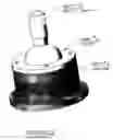
Drawing #1A Bearing Assembly with Alternate Housing Construction.
Drawing #2 Bearing Assembly, Exploded View
Drawing #3 Details of Free Zone Channel
Drawing #4 Rotational Movement of Ball and Shaft
Drawing #5 Angular Movement of Ball and Shaft
Drawing #6 Prior-Art Bearing Assembly
Illustration A Proof of Principle Model
Claims
1. A ball joint bearing assembly with ball bearings comprising of housing with free zone channel machined in it (Drawing #3, FIG. 2).
2. Said ball joint bearing assembly with cover having free zone channel machined in it (Drawing #3, FIG. 1).
3. The cross sectional size of the free zone channels in said ball joint bearing assemblies is larger than the ball bearings' diameter in order to facilitate their movement in the channel.
4. Ball bearings in said ball joint bearing assembly are free to follow the motion of the ball and shaft in the free zone channel.
5. The outer housing of said ball joint bearing assembly can be designed in various shapes and configurations.
6. Said ball joint bearing assembly must not have a full complement of ball bearings so as not to impede their free movement. Exact number of ball bearings must be determined for each size of the bearing assembly.
7. Said ball joint bearing assembly can be assembled by mechanical means (screws) or it can be assembled using electron beam welding. Welding can be accomplished along locating surfaces of the cover and housing.
8. The inner diameter in the cover of the said ball joint bearing assembly is smaller than the diameter of the ball on the shaft in order to maintain the integrity of the bearing assembly.
Images & Drawings included:
Sources:
- United States Patent and Trademark Office - verify current appl. status at the USPTO↗
Similar patent applications:
- » 20070031183
Ball Bearing Swivel Connector - » 20090008934
Swivel joint with uniform ball bearing requirements - » 20150042088
Swivel joint with uniform ball bearing requirements
Recent applications in this class:
- » 20250243898 2025-07-31
CONNECTION JOINT ARRANGEMENT - » 20240159264 2024-05-16
ADJUSTABLE BALL JOINT FOR AN INNER TIE ROD ASSEMBLY, ADJUSTABLE BALL JOINT KIT, AND METHOD OF ASSEMBLING AN ADJUSTABLE BALL JOINT - » 20210102573 2021-04-08
METHOD FOR PRODUCING A CONNECTION ELEMENT, AND CONNECTION ELEMENT - » 20170102027 2017-04-13
BALL JOINT HOUSING - » 20120150351 2012-06-14
Ball joint having a passageway for routing a cable therethrough - » 20120014743 2012-01-19
Mechanical double joint system - » 20120014742 2012-01-19
Mechanical double joint system - » 20120010033 2012-01-12
Tensioning Device with Pivotable Joint Connection - » 20110294584 2011-12-01
Universal ball joint - » 20110170943 2011-07-14
Quick plugging set of pneumatic tools